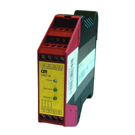
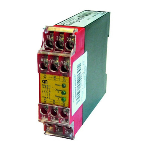
CM SAFE 5 User manual

181204 1
SAFE 5/5.1
CM Manufactory GmbH
Otto-Hahn-Str. 3
D-72406 B s ngen
Tel. +49-(0)7476-9495-0
Fax. +49-(0)7476-9495-195
www.cm-manufactory.com
Zielgruppe/
Target audience
Zeichenerklärung/
Explanation of
signs
⇒
,
Einleitung
D ese Bed enungsanle tung soll S e m t
dem Not-Halt S cherhe tsrela s und
Schutztürwächter SAFE 5 / SAFE 5.1
vertraut machen.
D e Bed enungsanle tung r chtet s ch an
folgende Personen:
Qual f z erte Fachkräfte, d e S cher-
he tse nr chtungen für Masch nen und
Anlagen planen und entw ckeln und
m t den Vorschr ften über Arbe tss -
cherhe t und Unfallverhütung vertraut
s nd.
Qual f z erte Fachkräfte, d e S cher-
he tse nr chtungen n Masch nen und
Anlagen e nbauen und n Betr eb
nehmen.
In d eser Bed enungsanle tung werden e -
n ge Symbole verwendet, um w cht ge In-
format onen hervorzuheben:
D eses Symbol steht vor Textstellen, d e
unbed ngt zu beachten s nd. N chtbeach-
tung führt zur Verletzung von Personen
oder zu Sachbeschäd gung
D eses Symbol kennze chnet Textstellen,
d e w cht ge Informat onen enthalten.
D eses Ze chen kennze chnet auszufüh-
rende Tät gke ten
Nach d esem Ze chen w rd beschr eben,
w e s ch der Zustand nach e ner ausge-
führten Tät gke t ändert.
©
opyright
Alle Rechte vorbehalten. Änderun-
gen, d e dem techn schen Fortschr tt d enen, vor-
behalten.
SAFE 5/5.1
Original Bedienungsanleitung
Sicherheitsschaltgerät für Not-Halt-
Kreise und Schutztürüberwachungs-
kontakte
Original operating instruction
Safety controller for e-stop and safety
gate monitoring applications
Introduction
Th s operat ng nstruct on should make
you fam l ar w th the
emergency stop and
safety gate mon tor ng relays
SAFE 5 / SAFE 5.1
The operat ng nstruct on s addressed to
the follow ng persons:
Qual f ed profess onals who plan and
develop safety equ pment for ma-
ch nes and plants and who are fam l-
ar w th the safety nstruct ons and
safety regulat ons.
Qual f ed profess onals, who nstall
safety equ pment nto mach nes and
plants and put them nto operat on.
The operat ng nstruct on conta ns sev-
eral symbols wh ch are used to h gh-l ght
mportant nformat on:
Th s symbol s placed n front of text
wh ch has to be absolutely pa d attent on
to. Nonobservance leads to ser ous nju-
r es or damage to property.
Th s symbol s placed n front of text,
wh ch conta ns mportant nformat on.
Th s s gn s placed n front of act v t es
After th s s gn follows a descr pt on on
how the s tuat on has changed after an
act v ty s performed.
©
opyright
All r ghts reserved. Changes, wh ch
serve techn cal mprovements are reserved.

181204 2
SAFE 5/5.1
Bestimmungsgemäße
Verwendung
Application:
Zu Ihrer Sicherheit
For your safety
Sicherheitshinweise
Das S cherhe tsrela s SAFE 5 / SAFE 5.1
s nd best mmt für den E nsatz n:
E n-oder zwe kanal ge Schaltungs-
techn k für Not-Halt-Schalter
E n-oder zwe kanal ge Schaltungs-
techn k m t Grenztaster für
Sch ebeschutzg tter.
Personen - und Sachschutz s nd n cht
mehr gewährle stet, wenn das S cher-
he tsrela s n cht entsprechend se ner be-
st mmungsgemäßen Verwendung e nge-
setzt w rd.
Beachten S e unbed ngt d e folgenden
Punkte:
Das Gerät darf nur unter Beachtung
d eser Bed enungsanle tung von
Fachpersonal nstall ert und n Be-
tr eb genommen werden, das m t den
geltenden Vorschr ften über Arbe ts-
s cherhe t und Unfallverhütung ver-
traut st. Elektr sche Arbe ten dürfen
nur von Elektrofachkräften durchge-
führt werden.
Beachten S e d e jewe ls gült gen
Vorschr ften, nsbesondere h ns cht-
l ch der Schutzmaßnahmen.
Reparaturen, nsbesondere das Öff-
nen des Gehäuses, dürfen nur vom
Hersteller oder e ner von hm beauf-
tragten Person vorgenommen wer-
den. Ansonsten erl scht jegl che Ge-
währle stung.
Verme den S e mechan sche Er-
schütterungen 10 g / 33 Hz be m
Transport und 2,5 g m Betr eb.
Mont eren S e das Gerät n e nem
staub- und feucht gke tsgeschütztem
Gehäuse; Staub und Feucht gke t
kann zu Funkt onsstörungen führen.
Sorgen S e für e ne ausre chende
Schutzbeschaltung be kapaz t ven
und ndukt ven Lasten an den Aus-
gangskontakten.
Safety indications
The safety relay SAFE 5 / SAFE 5.1 can
be used for:
S ngle-or dual channel capab l ty for
emergency stop.
S ngle-or dual channel capab l ty w th
l m t sw tches for safety gates.
Person and object – protect on aren’t
guarantee, f the safety relay sn’t use by
adequate def ne appl cat on.
Please note the follow ng po nts:
The un t should only be nstalled and
operated by persons, who are fam l-
ar w th both these nstruct ons and
the current regulat ons for safety at
work and acc dent prevent on.
Follow local regulat ons as regards
preventat ve measures.
Any guarantee s vo d follow ng
open ng of the hous ng or unauthor-
zed mod f cat ons.
Avo d mechan cal v brat ons greater
than 10 g / 33 Hz when transport ng
and 2,5 g n operat on.
The un t should be panel mounted n
an enclosure rated at IP 54 or better,
otherw se dampness or just could
lead to funct on mpa rment.
Adequate fuse protect on must be
prov ded on all output contacts w th
capac t ve and nduct ve loads.

181204 3
SAFE 5/5.1
13-14, 23-24
A1, A2
Aufbau und Funktionsweise
Ausgangskontakte:
S cherhe tsstrompfade (Schl eßer)
Für das Betre ben des Gerätes muss
e ne Versorgungsspannung an d e Klem-
men A1(+) und A2(-) angelegt werden.
D e LED "Pwr" leuchtet be geschlosse-
nem Not-Halt-Schalter.
Zum START des Gerätes muß d e
Klemme Y2 m t Y1 über e nen Schl eßer-
kontakt überbrückt werden. D e Funkt on
w rd be der Überbrückung der Klemmen
Y2 und Y1 gestartet.
Danach s nd d e Kontakte 13-14 und
23-24 geschlossen. D e LEDs Kanal 1
und Kanal 2 leuchten.
In Re he zu dem START-Taster kann
d e Schaltung e nes externen Schützes
überwacht werden (s ehe Anwendungs-
be sp el 2)
Var anten:
SAFE 5: m t Überwachung der
Start-Taste
SAFE 5.1: ohne Überwachung der
Start-Taste
Assembly and function
(function circuit diagram)
Output contacts:
safety c rcu ts (normally open)
An supply voltage must be appl ed at ter-
m nals A1(+) and A2(-). Power LED llu-
m nates f the emergency stop contact s
closed.
To START the un t, term nals Y2 and Y1
must be br dged w th a normally open
contact. The un t works f you close th s
contact.
At th s t me the contacts 13-14 and 23-24
are closed. The LED’s channel 1 llum -
nate, channel 2 llum nate.
In ser es to th s START-button an
external contactor can be controlled
(see appl cat on 2).
Dev ces:
SAFE 5: w th mon tor ng of the
start bottom
SAFE 5.1: w thout mon tor ng of the
start bottom
-
AC
A1
K1
K2DC
+
14 24
Überwachungslog k
A2
elektr.
S cherung
Y2 13 23Y1

181204 4
SAFE 5/5.1
Mechanische
Montage
mechanical
mounting
Elektrischer
Anschluß
Electronic
connection
Montage und Inbetriebnahme
Für e ne s chere Funkt on muss das S -
cherhe tsrela s n e n staub- und feucht g-
ke tsgeschütztes Gehäuse e ngebaut
werden (IP54).
Mont eren S e das S cherhe ts-re-
la s auf e ne Normsch ene
Führen S e d e Verdrahtung entspre-
chend des Verwendungszweckes durch.
Or ent eren S e s ch dabe an den An-
wendungsbe sp elen. Generell st das S -
cherhe tsrela s nach folgenden Angaben
zu verdrahten:
1. Akt v erungs- und Rückführungskre s
schl eßen
Automat sche Akt v erung:
Y2 – Y1 brücken oder externe
Schütze schl eßen.
(nur SAFE 5.1)
Bed ngte Akt v erung:
Taster an Y2 – Y1 anschl eßen
(ke ne Brücke an Y2 – Y1). Öff-
ner der externen Schütze werden
n Re he zum START-Taster an
d e Klemmen Y2 –Y1 ange-
schlossen.
Für Not – Aus - Funkt on, wo ke n auto-
mat scher Start erfolgen darf, w rd d e
Var ante SAFE 5 m t Überwachung des
Starttasters empfohlen.
Mounting and opening
The un t should be panel mounted n an
enclosure rated at IP 54 or better, other-
w se dampness or dust could lead to
funct on mpa rment.
There s a notch on the rear of the
un t for DIN-Ra l attachment.
Carry out the w re appropr ate the use.
Accord ng to the examples of appl cat on.
General the safety-relay has to be w re
under follow ng spec f cat ons:
1. Close the feedback control loop and
the act vat on c rcu t
Automat c act vat on: br dge Y2 – Y1
or close N.C. contacts of external
contactors.
(SAFE 5.1 only)
Cond t onal act vat on:
Connect button on Y2 – Y1 (no
br dge on Y2 – Y1). N.C. contacts of
external contactors are w red n se-
r es w th the START-button at the
term nals Y2 – Y1.
For emergency stop appl cat ons where
automat cally start sn't allowed, the ver-
s on SAFE 5 w th mon tor ng of reset/start
c rcu t s recommended.
Start über Start-Taste / start over start-button
Y2 Y1
Start
Automat sche Akt v erung / automat c act vat on
Y2 Y1
K2 ext
K1 ext
Start über Start-Taste und Anschluß
Masch nenfre gabekre se / Schützkontrolle
start over start-button and
connect on masch ne-release-c rcle
Y2 Y1
Start
Power +
14 24 Y2 A2
13 23
14 24
CH. 1 +
r ese
SAFE 5
A1 Y1 13 23
CH. 2 +

181204 5
SAFE 5/5.1
2. E ngangskre s schl eßen
E nkanal g: Schl eßen S e den
Kontakt des Auslöseelementes
an pos t ve Versorgungsspan-
nung und A1(+) an
Zwe kanal g: Schl eßen s e d e
Kontakte des Auslöseelementes
an pos t ve Versorgungsspan-
nung A1(+) und Masse A1(-) an.
3. Versorgungsspannung
U
V
24V AC/DC
S ehe Pkt.2
E nkanal g: Schl eßen S e d e
Versorgungsspannung U
V
(+) / L
(Phase) über den Kontakt des
Not-Halt- bzw. Schutztürschalters
an d e Klemmen A1(+) und U
V
(-)
/ N (Nullle ter) d rekt an d e
Klemme A2(-) an.
Zwe kanal g: Schl eßen S e d e
Versorgungsspannung U
V
(+) / L
(Phase) über den ersten Kontakt
des Not-Halt- bzw. Schutztür-
schalters an d e Klemmen A1(+)
und U
V
(-) / N (Nullle ter) über den
zwe ten Kontakt des Not-Halt-
Schalters an d e Klemme A2(-)
an.
Beachten S e unbed ngt d e max malen
Le tungslängen.
2. Close nput c rcu t
S ngle-channel: Connect con-
tacts from tr gger element to pos-
t ve supply voltage and
A1 (+).
Dual-channel: connect contact
from tr gger element to pos t ve
supply voltage – A1 (+) and
earth – A1(-).
3. Supply voltage
U
V
24V AC/DC
See po nt 2
S ngle-channel: The supply volt-
age U
V
(+) / L (phase) has to be
connected over the contact from
emergency stop / safety gate
mon tor ng to the term nal A1(+)
and U
V
(-) / N (neutral)
d rectly to term nal A2(-)
Dual-channel: over the second
contact from emergency
stop / safety gate
Mon tor ng to the term nal A2(-).
Please note the max. lengths of the ca-
bles.
Auslöse-
element
tr gger
element
A1 (+) A2 (-)
zwe kanal g / dual channel
24 VAC/DC
e nkanal g / s ngle-channel
A1 (+) A2 (-)
Auslöse-
element
tr gger
element
24 VAC/DC24 VAC/DC

181204 6
SAFE 5/5.1
Erdschluß bei
A - D -Variante
(mit elektr. Sicherung) /
Earth fault
A / D -version
(with electronic fuse
protection)
Fehlfunktion der
Kontakte /
Faulty contact
functions
Nur eine oder
keine LED leuchtet /
Only one or no
LED illuminates
Wartung und Reparatur
Das S cherhe tsrela s arbe tet wartungs-
fre .
Zum Austausch des Gerätes empfehlen
w r d e Kabel 1 zu 1 abzuschrauben und
an das Austauschgerät anzuschrauben.
1. Kabel abschrauben und an dem Aus-
tauschgerät anschrauben.
2. Defektes Gerät von der Hutsch ene
nehmen.
3. Austauschgerät auf Hutsch ene mon-
t eren.
Fehler/Störungen, Auswirkung
und Maßnahmen
D e S cherung löst aus. D e Ausgangs-
kontakte öffnen. Nach Wegfall der Störur-
sache und E nhalten der
Betr ebs-spannung st das Gerät
w eder betr ebsbere t.
Be verschwe ßten Kontakten st nach
Öffnen des Ausgangskre ses ke ne neue
Akt v erung mögl ch.
Externer Beschaltungsfehler oder nter-
ner Fehler. Externe Beschaltung prüfen.
Wenn Fehler mmer noch vorhanden,
Gerät an CM Manufactory GmbH e nsch -
cken.
Maintenance and repair
The safety – relay funct ons ma nte-
nance-free.
For exchange of the dev ce, we adv se to
screw off the term nals1 to 1 and to
screw on the exchange-dev ce.
1. You must screw off the cable and
screw on the exchange - dev ce.
2. Take away the defect ve dev ce from
the DIN - Ra l.
3. Mount the new dev ce on the DIN -
Ra l.
Faults, effect and measures
An electron c fuse release the output
contacts to open. Once the reason of the
d sturbance s removed and the rated
voltage s observed, the dev ce s ready
for operat on.
In the case of welded contacts, further
act vat on s not poss ble follow ng an
open ng of the nput c rcu t.
External w r ng or nternal fault s present.
Test the external w r ng.
When the flaw s st ll ava lable, send the
dev ce to CM Manufactory GmbH.

181204 7
SAFE 5/5.1
Technische Daten / Technical Data
Elektrische Daten / electrical data
Versorgungsspannung Uv / supply voltage 24V AC/DC
Spannungsbere ch / voltage range 0,85 ...1,1 U
V
Frequenz (AC-Var ante) / frequency (AC-type) 50 ... 60 Hz
Le stungsaufnahme ca. / power consumpt on appr.
ca. 1,6 VA / 1,6 W
Leitungsdaten / conductor data
Le teranschluß / conductor connect on 2,5 (2 x 0,75) mm
2
Mass vdraht (Cu) / mass ve w re
2,5 (2 x 0,75) mm
2
L tze (Cu) m t Hülse /
strand w th hull DIN VDE 46228
UL: Use 60/75°C copper w re only!
Max. Le tungslängen (E ngangskre s) /
max. conductor length ( nput c rcu t)
Le terquerschn tt / conductor cross-sect on 1,5 mm
2
Kapaz tät / capac ty 150 nF/km
W derstand / res stance 11,7 Ohm /km
Temperatur / temperature + 25°C
Max. Länge / max. length 2 x 0,5 km (e nkanal g/ ngle channel)
2x2 x 0,25 km (zwe kanal g / dual channel)
Kontaktdaten / contact data
Kontaktbestückung / contact-allocat on 2 S cherhe tsschl eßer / normally safety open
Kontaktart / contact type Rela s zwangsgeführt / relay pos t ve gu ded
Kontaktmater al / contact mater al AgSnO
2
oder vergle chbares Mater al /
AgSnO
2
or comparable mater al
Schaltspannung / sw tch ng voltage 250V AC, 24V DC
Schaltstrom / sw tch ng current 6 A
Max. Schaltvermögen / max. sw tch ng capab l ty
DIN EN 60947-5-1
AC 15 230 V / 3 A
DC 13 24 V / 3 A
Schaltle stung max. / max. sw tch ng capac ty 1500 VA (ohmsche Last) / 1500 VA (res st ve load)
Mechan sche Lebensdauer / mechan cal l fet me 10
6
Schaltsp ele / sw tches
Kr ech- und Luftstrecken / creep ng d stance and
clearance
-EN 50178 für Verschmutzungsgrad 2,
-Bas s sol erung: Überspannungskategor e 3 / 300 V
-EN 50178 at pollut on grade 2,
-bas s solat on: over voltage category 3 / 300 V
Kontaktabs cherung / contact secur ty 6,3 A fl nk oder 4 A träge DIN VDE 0660 Te l 200
6,3 A br sk or 4 A nert DIN VDE 0660 part 200
Kurzschlussfest gke t / Short C rcu t W thstand
entsp. / acc IEC60947-5-1
Weld Free Protect on at IPSCC≥1kA
SCPD*) (Vors cherung / Fuse l nks), Gebrauchskategor e / s ze D01
gL/gG nach / acc IEC IEC60269-1; IEC60269-3-1; VDE036-T301
*) Short C rcu t Protect on Dev ce
Schl eßer / NO-contacts: 10A
Öffner / NC-contacts: 4A
W ederbere tschaftsze t (m n male Abschaltze t der
E ngänge) / restart ng read nes t me (m n mum sw tch
off t me the nputs) 0,5 s
Rückfallverzögerung K1/delay on deenerg sat on K1 < 50 ms (DC) / < 80 ms (AC)
Mechanische Daten / mechanical data
Gehäusemater al / hous ng mater al Polyam d PA 6,6
Abmessungen (BxHxT) n mm / d mens ons ( bxhxd ) 22,5 x 114,5 x 99
Befest gung / fasten ng Schnappbefest gung für Normsch ene / cl ck-fasten ng for DIN-Ra l
Anzugsmoment für Anschlussklemmen / Torque
sett ng for connect on term nals m n. 0,5 Nm / max. 0,6 Nm
(UL: „T ghten to 0.5-0.6 N.m. Overtorqu ng may cause enclosure breakage“)
Gew cht m t Klemmen / we ght w th term nals Max. 130g
Lagerung / storage In trockenen Räumen / n dry areas
Umgebungsdaten / environmental data
Umgebungstemperatur / operat ng temperature -25°C ... +55°C (UL: +40°C)
Luftfeuchte / hum d ty 95% 0-50°C
Schutzart Klemmen / term nal type IP 20 DIN VDE 0470 Te l 1 / part 1
Schutzart Gehäuse / hous ng type IP 40 DIN VDE 0470
Stoßfest gke t / m Betr eb / shock res stance / n
operat on
10 g / 2 g, 33 Hz VDE 0160
Zertifizierungen / certifications
Geprüft nach / tested n accordance w th EN ISO 13849-1
Erre chtes Level/Kategor e / ach eved level/category Performance Level e, Kat. 3
MTTFd [Jahre] / MTTFd [years] 71 “hoch/h gh”
DC 90% “m ttel/med um”
CCF erfüllt/ach eved

181204 8
SAFE 5/5.1
b s Kategor e 2; SIL1; PLd er-
re chbar
up to category 2; SIL1;PLd
reachable
b s Kategor e 2; SIL1; PLd er-
re chbar
up to category 2; SIL1; PLd
reachable
b s Kategor e 2; SIL1; PLd er-
re chbar
up to category 2; SIL1; PLd
reachable
Anwendungsbeispiele
Beispiel 1: Einkanalige
Not-Halt-Schaltung.
M t dem START-Taster w rd das Gerät
akt v ert. D e Kontakte 13-14, 23-24
schl eßen. Über den AUS-Taster oder
Not-Halt fallen d e Kontakte n hre
Grundstellung zurück.
Beispiel 2: Einkanalige Not-Halt-Schal-
tung mit externer Kontakterweiterung
(2 Schütze) und Kontaktüberwachung.
In d esem Be sp el werden 2 externe
Schütze m t Kontaktzwangsführung ver-
wendet. Je e n Öffnerkontakt d eser be -
den Schütze muß n Re he zum START-
Taster angeschlossen werden. Über e -
nen Schalter S ext. können d e externen
Schütze zu e nem bel eb gen Ze tpunkt
dazugeschaltet bzw. abgeschaltet wer-
den, wenn das SAFE 5... akt v ert st.
Beispiel 3: Einkanalige Schutztürüber-
wachung
W rd der Schutztürtaster S 1 geschlos-
sen, ble ben d e Ausgangskontakte un-
verändert. Erst m t der START-Taste w rd
das Gerät akt v ert. D e Kontakte 13-14,
23-24 schl eßen. Be m Öffnen des
Schutztürtasters fallen d e Kontakte un-
verzögert n hre Grundstellung zurück.
M ttels e ner Brücke zw schen Y2-Y1 st
e ne automat sche Akt v erung mögl ch.
D ese Funkt on st nur m t der Gerätevar -
ante SAFE 5.1 mögl ch.
Ergänzender Hinweis
Be entsprechender Verdrahtung nach
Appl kat onsbe sp elen 1 b s 3 muss
durch den Anwender e ne Anb ndung an
d e Masch nensteuerung für d e zykl sche
Testung erfolgen.
Examples for applications
Example 1: Single-channel emergency
stop.
Press ng the START-button, the un t w ll
be act vated. Contacts 13-14, 23-24 are
closed. Press ng the emergency stop w ll
reset the contacts.
Example 2: Single-channel emergency
stop with external contact extension
(2 contactors) and contact monitoring.
In th s appl cat on uses two external pos -
t ve gu ded contactors. One normally
closed contact of each contactor must be
connected n ser es to the START-button.
Through the sw tch S ext. the external
contactors can be operated or turned off
at any t me the SAFE 5... s act vated.
.
Example 3: Single-channel gate moni-
toring
If the button S1 of the gate s closed the
output contacts do not change. Press ng
the START-button act vates the SAFE 1..
The contacts 13-14,23-24 are closed.
Open ng S1 of the safety gate the out-
puts open mmed ately. By br dg ng the
START-button term nals Y1 and Y2 the
relay w ll start automat cally and reset au-
tomat cally. Automat c start and reset
start s only poss ble us ng the SAFE 5.1
vers on.
Additional advice
W th w r ng accord ng to appl cat on ex-
amples 1 to 3 the user must prov de a
connect on to the mach ne control for cy-
cl c test ng.
Y1 Y2 23A2(-)A1(+) 13
24V AC/DC
14 24
Start
Not-
STOP
E-
Halt/
Y1 Y2 23A2(-)A1(+) 13
24V AC/DC
14 24
K1
K2
K1
K2
Sext
Uext
Start
Not-
STOP
E-
Halt/
Y1 Y2 23A2(-)A1(+) 13
24V AC/DC
14 24
Start

181204 9
SAFE 5/5.1
Y1 Y2 23A2(-)A1(+) 13
24V AC/DC
14 24
Start
E-Stop
b s Kategor e 3; SIL2; PLd er-
re chbar
up to category 3; SIL2; PLd
reachable
(m t getrennten
Mantelle tungen)
b s Kategor e 3; SIL2; PLd er-
re chbar
up to category 3; SIL2; PLd
reachable
(m t getrennten
Mantelle tungen)
b s Kategor e 3 nach Val d e-
rungsber cht LP.520.28(FA) von
BGFE von 03.08.2006; SIL2;
PLd erre chbar
up to category 3; SIL2; PLd
reachable
Beispiel 4: Zweikanalige Not-Halt-
Schaltung.
Be der zwe kanal gen Not-Halt-Schal-
tung werden d e Öffnerkontakte des Not-
Halt-Schalters n Re he zur Spannungs-
versorgung geschalten. M t dem START-
Taster w rd das Gerät akt v ert. D e Kon-
takte 13-14, 23-24 schl eßen. Über den
Not-Halt-Schalter fallen d e Kontakte n
hre Grundstellung zurück.
Beispiel 5: Zweikanalige Schutztür-
überwachung.
Werden d e Schutztürtaster geschlossen,
ble ben d e Ausgangskontakte unverän-
dert. Erst m t der START-Taste w rd das
Gerät akt v ert. D e Kontakte 13-14, 23-
24 schl eßen. Be m Öffnen der Schutztür-
taster fallen d e Kontakte unverzögert n
hre Grundstellung zurück. M ttels e ner
Brücke zw schen Y2-Y1 st e ne automa-
t sche Akt v erung mögl ch. D ese Funk-
t on st nur m t der Gerätevar ante SAFE
5.1 mögl ch.
Beispiel 6: Öffnerschaltleiste SL/N II
von Mayser
D e Öffnerschaltle ste w rd w e e n e nka-
nal ger Not-Halt-Schalter n Re he zum
Versorgungskre s A1 e ngeschle ft. W rd
d e Schaltle ste betät gt w rd d e Energ e-
zufuhr zum Schaltgerät unterbrochen und
d e S cherhe tskre se 13/14 und 23/24
öffnen. Be der Verlegung der be den Ka-
bel zur Öffnerle ste muss auf e ne dauer-
hafte und gegen äußere Beschäd gung
geschützte Verdrahtung geachtet wer-
den.
Example 4: Dual-channel emergency
stop.
For th s appl cat on the normally closed
contacts of the emergency STOP-button
must be connected n ser es to the power
supply. W th the START-button the un t s
started. The contacts 13-14, 23-24 are
closed. Press ng the emergency stop w ll
rest the contacts.
Example 5: Dual-channel safety gate
monitoring.
If the safety gate sw tches S1 and S2 are
closed, the output contacts rema n un-
changed. The dev ce w ll be act vated
w th the START-button. Contacts 13-14,
23-24 are closed. Open ng the safety
gate sw tches return the contacts mme-
d ately to the r normal pos t on. By br dg-
ng the START-button term nals Y2 and
Y1 the relay w ll start automat cally and
reset automat cally. Automat c start and
automat c reset s only poss ble us ng the
SAFE 5.1 vers on.
Example 6: Opener onnecting Block
by Mayser
The opener connect ng block s con-
nected n ser es l ke a s ngle channeled
emergency stop to supply c rcu t A1. In
case of act vat ng the connect ng block,
the power supply to the sw tch ng dev ce
s d sconnected an d e safety c rcu ts
13/14 and 23/24 open.
When lay ng both cables to the opener bar
there s to pay attent on for an everlast ng
w r ng protected aga nst external damage.
Y1 Y2 23A2(-)A1(+) 13
14 24
Start
Mayser
SL/NC
II
24VDC 0V
Y1 Y2 23A2(-)A1(+) 13
24V AC/DC
14 24
Start
S

181204 10
SAFE 5/5.1
Gerätevarianten / Devices
Name / Name: Spannung / Voltage: Artikel-Nummer. / Article number:
SAFE 5 24 V AC/DC 45228 AR.9645.2000
SAFE 5.1 24 V AC/DC 45232 AR.9646.2000
This manual suits for next models
1
Table of contents
Other CM Controllers manuals
Popular Controllers manuals by other brands

Ingersoll-Rand
Ingersoll-Rand 302 SERIES Installation and operation manual

Zumtobel
Zumtobel ED-CCS 1/2/3 Li1/Li2 manual

Enttec
Enttec DIN-ODE MK2 user manual

Konig & Meyer
Konig & Meyer 18819 manual

PRECISION DIGITAL
PRECISION DIGITAL ProVu Series instruction manual

Dadam micro
Dadam micro ABC-2 Series user manual