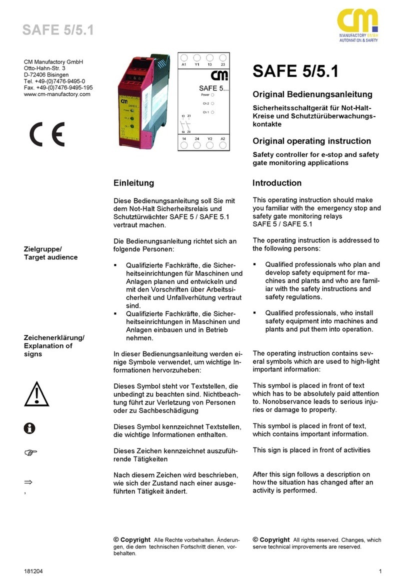
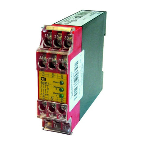
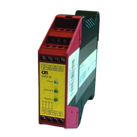
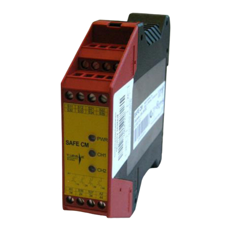
CM Three-Phase Perfection Premium Series User manual

Microprocessed Voltage Regulator
Three-Phase Perfection Premium Series
User´s Manual
CM COMANDOS LINEARES - 1/38 -
Three-Phase
Perfection
Premium
Series
Voltage Regulator
User´s Manual
1 - Rev –1 Version
10.0 to 100.0 kVA

Microprocessed Voltage Regulator
Three-Phase Perfection Premium Series
User´s Manual
CM COMANDOS LINEARES - 2/38 -
Table of Contents
Security Regulations ________________________________________________________3
Receipt __________________________________________________________________4
Receipt Inspection by the Client _______________________________________________4
Refusal of the Material_______________________________________________________5
Receipt with Reservations ____________________________________________________5
Handling _________________________________________________________________6
Storage __________________________________________________________________7
Installation ________________________________________________________________8
Preparation –Choice of local and environment setting ______________________________8
Positioning________________________________________________________________9
Composition______________________________________________________________10
Electrical Connections –typical installation sketches ______________________________10
* For other voltages, please, consult CM Comandos Lineares´ Applications Engineering
Department. Placement of Internal Components__________________________________11
Cable Terminal Block_______________________________________________________13
IT Model Connection Label __________________________________________________14
Terminal Label____________________________________________________________14
OUTPUT NEUTRAL _______________________________________________________14
GROUND________________________________________________________________14
Cable Connections ________________________________________________________15
Initial activation ___________________________________________________________16
Functional Check__________________________________________________________18
Failure Reset or Alarm, with Connected Load. ___________________________________18
Voltage regulator Operation Recommendation ___________________________________18
Functioning Theory ________________________________________________________19
System Description ________________________________________________________19
Purpose: ________________________________________________________________19
Applications ______________________________________________________________19
Performance _____________________________________________________________19
Stabilization Principle_______________________________________________________20
Panel Messages and Measurements___________________________________________21
Normal Operation _________________________________________________________21
Baud Rate Serial __________________________________________________________21
Serial Number ____________________________________________________________22
Sound Alarm _____________________________________________________________22
Date & Time______________________________________________________________22
Output Power KVA_________________________________________________________22
Output Power KW _________________________________________________________22
Network Frequency ________________________________________________________22
RST Output Voltage________________________________________________________22
RST Input Voltage _________________________________________________________22
Alarm Description _________________________________________________________23
Under and Over Voltage Protection____________________________________________25
System with Automatic Reset ________________________________________________26
Main Characteristics _______________________________________________________26
Technical Specifications ____________________________________________________27
Physical Dimension Table ___________________________________________________29
IT Models –Isolated Three-Phase_____________________________________________29
TA Models –Three-phase with input auto transformer _____________________________29
T Models –Three-phase without input transformer ________________________________30
Internal Circuit Breaker Table ________________________________________________30
Preventive Maintenance ____________________________________________________31
First Aid _________________________________________________________________32
Corrective Maintenance_____________________________________________________34
Procedures to open a technical call____________________________________________34
Accredited Network ________________________________________________________34

Microprocessed Voltage Regulator
Three-Phase Perfection Premium Series
User´s Manual
CM COMANDOS LINEARES - 3/38 -
Terms of Warranty_________________________________________________________35
Warning!
This manual contains instructions on Receipt, Handling, Storage, Installation,
Placement, Initial Activation and Operation of the Perfection Premium Series
Voltage Regulator. Read this manual carefully before performing the installation
procedures, which should be carried out by trained personnel.
Whenever needed, we recommend that this manual be available near the
equipment, in an accessible place, in order to be consulted prior to operating the
voltage regulator.
Security Regulations
This equipment should not be used if not connected to the local grounding
system.
The first connection to be made is the Ground Wire, coming from the Ground
Rod or its respective derivation from the switchboard to the equipment
terminal identified as GROUND.
In some versions of the equipment, the neutral input connection point as well
as the output, is connected internally, being a common point.
All maintenance operation inside the voltage regulator must be carried out
solely by trained personnel. There are internal points that even after turned
off may maintain stored voltages that can cause accidents.
Should you need to replace fuses, they must be of the same value as the
original. Failure in following these procedures may cause irrecoverable
damage to the voltage regulator and to your facilities.
Grounding the Voltage Internally Energized

Microprocessed Voltage Regulator
Three-Phase Perfection Premium Series
User´s Manual
CM COMANDOS LINEARES - 4/38 -
Regulator Before Operating Voltage regulator
Receipt
CM Comandos Lineares is certified with Standard ABNT NBR ISO-9001:2008, and
its Quality System monitors the efficiency of material transportation from the factory
to the client.
When the product is collected by the carrier in our plant, the carrier is assessed
upon each individual Collection Procedure through a Carrier Assessment Form.
Thus, the condition of the product upon collection, regardless the freight contract, is
kept in record files, i.e., whether the transportation has been paid for by the client
of not.
The carrier, on the other hand, receives the Product Handling Recommendation
and, upon each collection, signs an Acknowledgement Declaration of the same.
Finally, upon Product Delivery to the client, the acceptance of the Road Bill of
Lading and the signature of the DANFE tag (Electronic Invoice Auxiliary Document)
by the client will attest that the product has been received in perfect condition.
At this stage of receipt, we request your cooperation so as to avoid further
inconveniences by verifying the product on possible damage as a result of the
transportation.
Receipt Inspection by the Client
The basic points to be checked are:
1. Amount of volumes indicated on the DANFE (Electronic Invoice Auxiliary
Document).
2. Package General Aspect –check if there are no wrinkled edges or any visible
indication of fall during transportation.
3. Check for evidences of humidity in the package due to rain or contact with other
liquids.
In case of any problem, get in contact with CM together with the carrier. Determine,
upon receipt, the Refusal of Acceptance or Receipt With Reservations.
The refusal implies in the devolution of the product with the responsibility laid on
the carrier for damage.

Microprocessed Voltage Regulator
Three-Phase Perfection Premium Series
User´s Manual
CM COMANDOS LINEARES - 5/38 -
The caveat characterizes the partial receipt for the cases of small proportion
damage. CM will send a technician to perform the repair in loco on the carrier´s
cost.
Important: the refusal or caveat is the only way to lay responsibility on the
carrier for the quality of transportation services.
Refusal of the Material
In order to formalize the refusal, follow the next procedures:
1. Behind the DANFE (Electronic Invoice Auxiliary Document), describe the
reason for refusal, the collector´s legible name, date and time of receipt.
2. Specify the condition of the package on the second copy of the Road Bill of
Lading or in a specific form from the carrier, in case they have one.
3. The carrier will return the material to CM who will service the equipment under
the carrier´s liability.
4. After servicing, the carrier will return the serviced product to the client.
Receipt with Reservations
In order to formalize the Receipt With Reservations, follow the next procedures:
1. Specify the condition of the package and affected parts on the second sheet of
the Road Bill of Lading or on a specific form offered by the carrier, in case they
have one. Write the legible receiver´s name, date and time of receipt.
2. Sign the DANFE tag (Electronic Invoice Auxiliary Document) and send a copy of
the Road Bill of Lading with the notes of caveat.
3. The product is accepted with the carrier assuming responsibility for the
servicing of any damaged part: caster cover, etc.
4. CM will send a technician with all expenses on the carrier.

Microprocessed Voltage Regulator
Three-Phase Perfection Premium Series
User´s Manual
CM COMANDOS LINEARES - 6/38 -
Handling
We recommend the correct handling through compatible equipment with its
dimension and weight.
The package is fit for use with trans-pallet carts, or hoisted through a Munk type
truck with the aid of suitable belts, or with the use of trucks fitted with a lifting
platform.
The voltage regulator, despite its size and weight which, depending on the model
can assume higher value, is a sensitive electronic piece of equipment, bearing
power subassemblies and electronic boards with micro controller circuits,
processors and liquid crystal display that can suffer irreparable damage due to
handling.
We recommend the maximum care possible not to damage the external parts such
as the front panel, duly identified in the package, as well as side, top and rear
covers.
Most voltage regulators are endowed with self sustaining casters for easy handling,
however, they are potential points for damage when not handled appropriately. We
recommend maximum attention during the move.
We remind you that any damage due to incorrect handling, as well as any physical
damage to the cabinet and painting, will not be covered by the warranty.
Handling with trans-pallet Pallet Removal

Microprocessed Voltage Regulator
Three-Phase Perfection Premium Series
User´s Manual
CM COMANDOS LINEARES - 7/38 -
Detail of pallet removal with Munk type truck hydraulic gear.
Storage
By proceeding correctly with the Receipt step, make sure the equipment is stored
in a safe place, sheltered, and away from humidity.
The Storage Ceilings are as follows:
Ambient Temperature: 0oto 40o C (104oF)
Relative Air Humidity: 90% maximum –non-condensing

Microprocessed Voltage Regulator
Three-Phase Perfection Premium Series
User´s Manual
CM COMANDOS LINEARES - 8/38 -
Installation
Preparation –Choice of local and environment setting
The Premium Perfection Series Voltage Regulator is strongly built and may
function under diverse conditions, however, the choice of the installation place will
influence very much on the life of the components and frequency of maintenance.
The shelter area must be clean, free of dust, corrosive gases, sea-side air,
humidity, drippings and suspended conductive particles.
The area around the equipment, especially its base, sides and ventilation outflow,
must be clear of objects that may obstruct the input and outflow air.
The cleaning of the floor beneath the humidity must be done with a vacuum
cleaner, broom or brush, and must only be done after interrupting the voltage
regulator electric power.
Check if the floor is compatible and supports the weight of the unit. Refer to the
Physical Dimensions Table in the Technical Specifications chapter in this manual.
Good lighting, easy access to the area and provision of physical space, will ensure
easy access to the internal components, and it must be taken into consideration in
order to facilitate any technical interventions and reduce MTTR –Medium Time to
Repair.
On the other hand, unfavorable environments, with difficult access to technical
personnel, increase MTTR or even hinder such tasks.
The recommended the ambient temperature be from 20º C to 25º C under low
relative humidity.
The methods to suit the ambient temperature where the voltage regulator will be
installed can be:
- Natural Ventilation: applicable when the environment is kept under the desired
limits.
- Forced Ventilation: applicable only when the outer temperature is lower than the
room where the voltage regulator will be housed.
- Air Conditioning: applicable when the outer temperature is higher than the
room where the voltage regulator will be housed.

Microprocessed Voltage Regulator
Three-Phase Perfection Premium Series
User´s Manual
CM COMANDOS LINEARES - 9/38 -
Positioning
At the time of positioning the voltage regulator, consider the following factors:
A minimum space of one meter front wise from the equipment for access to the
frontal panel and operational commands.
A minimum space of 40 centimeters between the back of the voltage regulator and
the wall so as not to obstruct the inner exhaust fan air flow. For models with 20 kVA
maximum power, the free space for the upper part must be considered in 40
centimeters.
We recommend objects not to be placed onto the voltage regulator. The cable
entry must be done by using flexible auto-type cables only. For gauges above 25
mm2, we recommend the use of welding type cables, or similar.
The cable plumb must be sized considering a minimum gap of 1.5 meters between
the exit point of the cables from the bed to the equipment terminal block.
For places with difficult access and lateral space below 1.0 meter, we recommend
to double the size and length of the cables, thus facilitating the forward
displacement of the voltage regulator freeing the access to the inner parts.
The connecting terminals from the voltage regulator input and outlet cables are
located in the frontal lower part. Consider a height of 30 cm between the floor and
the connecting terminals, besides the needed gap of 2.0 to 4.0 meters for the whip
as from the recommended above.
Note.: For models with power up to 20KVA the air exhaust is done from the rear
part. Above 20KVA the air exhaust is done from the upper part.
AIR
EXHAUST
MINIMUM WALL
DISTANCE
40 CM
AIR
EXHAUST
POWER BOX
Input and output
terminals
30 cm height
CABLE INPUT
UNDERNEATH THE UNIT
SPARE CABLE
MINIMUM 1.5 METERS

Microprocessed Voltage Regulator
Three-Phase Perfection Premium Series
User´s Manual
CM COMANDOS LINEARES - 10/38 -
Composition
The typical system consists of a Premium Perfection Series Voltage regulator, of
adequate power, according to the requested model.
Other items for the installation of the system are up to the client, since they depend
on variable factors according to the demands of the project.
All information contained in this manual are enough for most installation cases. CM
Command Lineares´ Applications Engineering Department is available to the users
for any clarification and suggestions.
Electrical Connections –typical installation sketches
In this chapter you will find representations of damage by dimensioning and
suggestions for the electrical installation. We recommend the thorough
understanding of the topics described herein for further installation
execution.
In case of doubt, please, immediately consult our Applications Engineering
Department.
In the following illustration, we suggest an electrical diagram of a typical
installation, comprised of a Power Box containing circuit breakers, protection
circuits and electric cables.
For the correct sizing of the conductors and protection devices, refer to the Circuit
Breakers and Cable Sizing Table, sent by the commercial department along with
the Order Confirmation, or further request one from our Technical Assistance
Department.
The table presents metric gauges in mm2for connections up to Ten (10) meters in
conduit or overlapping passage ducts. For greater distances and/or imbedded
cables and ducts, please refer to our Applications Engineering Department.
The voltage regulator will feed a distribution frame with several circuits protected by
independent circuit breakers. This procedure enables sectioning and/or individual
protection in case of overcharge or individual maintenance operations, without
interfering in the functioning of the remaining circuits, avoiding possible
disturbances in the overall distribution in case of local failure.

Microprocessed Voltage Regulator
Three-Phase Perfection Premium Series
User´s Manual
CM COMANDOS LINEARES - 11/38 -
Installation Sketch
.
.
Typical installation sketch –refer to the Circuit Breaker and Cable Table, or to the Applications
Engineering Department for the correct sizing of circuit cables.
Consider the input neutral conductor in the versions:
Perfection Premium Series - TA
Perfection Premium Series - T
Perfection Premium Series - IT(with 380V input voltage)*
* For other voltages, please, consult CM Comandos Lineares´ Applications Engineering
Department.
AC Power
Ground
POWER
BOARD
Ground

Microprocessed Voltage Regulator
Three-Phase Perfection Premium Series
User´s Manual
CM COMANDOS LINEARES - 12/38 -
Placement of Internal Components
The images are merely illustrative. The place of some components may vary without previous notice,
depending on the model and configuration of the voltage regulator.
Front
Panel
Input
Circuit
Breaker
Contactor
Manual
Bypass Key
Terminal for
input cables

Microprocessed Voltage Regulator
Three-Phase Perfection Premium Series
User´s Manual
CM COMANDOS LINEARES - 13/38 -
Cable Terminal Block
The input and output cable connection terminals are placed in the frontal part of the
voltage regulator.
The terminal block has numbered identification with respective input and output
connection inscription. There is also an inscription with the identification of the
voltage regulator´s input and output configuration identification.
Delta - Star Configuration
Default configuration for IT models –Isolated Three-Phase. (with 220V input
voltage).
Star - Star Configuration
Default setting for models:
IT –Isolated Three-Phase with 380V electric voltage.
TA –Three-Phase with autotransformer.
T –Three-Phase without input transformer.
These models demand Neutral input connection
THREE-PHASE - THREE PHASE
PHASE
GROUND
PHASE
PHASE
NEUTRAL
PHASE
PHASE
PHASE
DELTA
INPUT
STAR
OUTPUT
THREE-PHASE - THREE PHASE
PHASE
PHASE
PHASE
PHASE
GROUND
NEUTRAL
NEUTRAL
PHASE
PHASE
STAR
INPUT
STAR
OUTPUT

Microprocessed Voltage Regulator
Three-Phase Perfection Premium Series
User´s Manual
CM COMANDOS LINEARES - 14/38 -
IT Model Connection Label
.
Mod: 001A
Terminal Label
Warning !
IT TERMINAL LABEL
R1 - INPUT PHASE R
S1 - INPUT PHASE S
T1 - INPUT PHASE T
NEUTRAL MAINS (380V only)
R - OUTPUT PHASE R
S - OUTPUT PHASE S
T - OUTPUT PHASE T
OUTPUT NEUTRAL
GROUND
We recommend
the use of
flexible cables
Risk of bad
contact
Tighten all
bolts before
operation
Mod. 001B_R01
For safety, the voltage regulators always leave the plant with the closing of
the input terminals for 380V voltage. If a change to 220V is needed, follow
the instruction on the terminal label above by changing the input closing
for 220V.
220V input
Ground
380V input
Neutral
MAINS
Ground

Microprocessed Voltage Regulator
Three-Phase Perfection Premium Series
User´s Manual
CM COMANDOS LINEARES - 15/38 -
Cable Connections
Prior to connecting the cables, it is always important to verify the input voltage
available and the desired output voltage, matching the specific values on the
voltage regulator identification label.
Warning! : Upon energizing the equipment with incorrect voltages, our liability is
waived with regards to the voltage regulator Warranty.
1. Before starting to connect the voltage regulator cables, check if the circuit
breaker in the input board is actually open (DESL-OFF).
2. Check if the circuit breaker located in the frontal part of the equipment is open
(DESL-OFF) before making the connections.
3. The first connection to be made to the equipment terminal block must be the
GROUND cable.
4. Connect the feeding circuit in the voltage regulator output terminal block,
respecting the phase sequence R, S and T.
Note.: In the Cable Terminal Block topic, check if the voltage regulator to be
installed needs the input Neutral. For some models, the use of the Neutral is
mandatory.
Keep the output circuit cables temporarily isolated and disconnected.
As a default procedure in this manual, firstly, run the voltage regulator test by
turning it on, on empty, and verifying its performance. Once approved, connect
the output circuit cables and finish the tests.
In case of problems on this second phase, there might be failure in the output
circuit (outlet or bus failure, or inverted cables, etc).

Microprocessed Voltage Regulator
Three-Phase Perfection Premium Series
User´s Manual
CM COMANDOS LINEARES - 16/38 -
Initial activation
Connect the input circuit breaker on the Power Board, energizing the voltage
regulator input.
With a multimeter, measure the voltage on the voltage regulator input terminals,
checking for the presence of voltage of the three phases in relation to the Neutral
and Ground, as well as between the phases.
Check if the values obtained are within the voltage regulator operational range, as
from the information contained on the Technical Specification Table.
All being in accordance, check if the manual bypass key is in the off position and
turn on the voltage regulator input circuit breaker.
By following this procedure, the front panel will light displaying the message Press
Enter to Start.
Press the Enter button on the panel and observe the sequence of messages
on the table as from below:
Checking
Initial Condition
Analyzes the input phase sequence.
Booting the
Voltage regulator
Analyzes the input voltage and frequency.
Triggering
Rectifier
Turns on the rectifier and contactor (Bypass output).
Triggering
Inverter
Turns inverter on (Bypass output).
Triggering
Control
Verifies the action of the control (Bypass output).
Normal Operation
CM Comandos Lineares
Stabilized Output Voltage.

Microprocessed Voltage Regulator
Three-Phase Perfection Premium Series
User´s Manual
CM COMANDOS LINEARES - 17/38 -
If the panel shows the message: Incorrect Phase Sequence, after pressing the
Enter button, turn off the voltage regulator and circuit breaker on the Power Board,
invert two input phases (E.g., R phase with S phase), turn on the circuit breaker
again on the Power Board and voltage regulator and proceed with the tests.
Incorrect Phase Sequence
Input phase needs inversion.
After the Normal Operation –CM Comandos Lineares indication, measure the
voltage on the voltage regulator output terminal with a multimeter. The mean
voltage must be close to the nominal value indicated on the Identification Label,
with a precision of 1% above the nominal value.
By using the button above or below , select the option Output Voltage,
compare the measurements taken with a multimeter and the ones indicated on the
panel.
All being in accordance, select the Turn Off Voltage Regulator? option on the
panel, press the Enter button. It will display the message Turn Off? Press Enter.
Press the Enter button again to confirm the shutting off of the voltage regulator.
Next, the screen will display the message Press Enter to Start.
Turn off the equipment through the internal circuit breaker, also turn off the circuit
breaker on the Power Board.
Now connect the output circuit cables, once having tested the functioning of the
voltage regulator. The only thing left on this phase is to feed the output circuit.
Turn on the Power Circuit Breaker on the Power Board and next turn on the
Voltage Regulator Circuit Breaker.
Switch the manual bypass key to the on position. At this point the output contactor
is activated energizing the output terminals and the circuits on the distribution
board on the voltage regulator panel. It will display the message Manual Bypass
Activated.
On the output distribution board, firstly trigger the general circuit breaker and next,
one output circuit at a time, measure the plugs fed, of each circuit, observing the
Phase, Neutral and Ground polarity of each one of them. Repeat this procedure
for the remaining circuits. Remember that at this point the voltage regulator is still
in the bypass mode.
Switch the manual bypass key to the Off position. The panel will display the
message Press Enter to Start.
Press the Enter button. The screen will display the initialization messages
according to the above mentioned. Wait for the message Normal Operation –CM
Comandos Lineares.

Microprocessed Voltage Regulator
Three-Phase Perfection Premium Series
User´s Manual
CM COMANDOS LINEARES - 18/38 -
Functional Check
Once verifying the power outlets, connect any consumer´s equipment, preferably a
personal computer or any piece of equipment with easy visual identification of
operation.
Again, verify the output voltage in the operational condition by feeding the output
charge. The values must be kept in levels within the output precision.
In order to simulate a bypass condition, press one of the arrows on the panel
(above or below) until you reach the Transfer Bypass? Press Enter option. Press
the Enter button. A new message Voltage Regulator Transfer Bypass? will be
displayed. Press the Enter button again.
At this point the voltage regulator will switch to bypass, the panel will display the
Bypass Command Activated message followed by three beeps per second.
To return to the normal condition, select through the arrow the option Return
Bypass? Press Enter, press the Enter button and then the Return Voltage
Regulator Bypass? message will be displayed. Press the Enter button again. The
voltage regulator will return to the normal operation condition indicating the Normal
Operation CM –Comandos Lineares message on the panel.
Having run these procedures, the voltage regulator is suitable for normal operation
fed by the distribution circuits with stabilized energy.
It is important to verify with the consuming circuits in use, if the consumed values
on the panel, per phase, are within the specified limits in accordance with your
voltage regulator model. These values are indicated on the panel by the power
indications in Watts and VA.
In case of doubt about the total consumption of the critical load, consult CM
Comandos Lineares´ Applications Engineering Department.
Failure Reset or Alarm, with Connected Load.
In case of failure or alarm indication in the voltage regulator, it is possible to
perform a reset without disconnecting the load already connected. Follow the steps
below:
1. Activate the manual bypass key located in the frontal part of the voltage
regulator to the on position.
2. Wait for the Manual Bypass Activated indication to appear on the panel.
3. Turn off the manual bypass key. Wait for the display of the message Press
Enter to Start.
4. Press the Enter button. The voltage regulator must start. Wait for the Normal
Operation CM Comandos Lineares message.
Note.: If the failure persists, consult CM Command Lineares´ Technical
Assistance.
Voltage regulator Operation Recommendation

Microprocessed Voltage Regulator
Three-Phase Perfection Premium Series
User´s Manual
CM COMANDOS LINEARES - 19/38 -
The voltage regulator can be kept turned on, on empty, at the end of a day´s
journey by just turning off the connected loads to its output.
In this condition its consumption on empty will be minimum due to its high electrical
yield. This situation is recommended for most cases.
Functioning Theory
System Description
The Perfection Premium Series voltage regulator is an equipment that corrects
voltage variations from the Mains through an innovative IGTS converter
technology, controlled by DSP chip, a unique system in the world market
developed by CM Comandos Lineares, which also includes the registration of a
Log of Events that keeps 25,500 records, allowing for Operation History
Traceability.
Purpose:
The main purpose is to isolate the Mains variations, protecting the consumer
against transients and voltage oscillations, supplying a clean sine wave, void of
harmonic distortions. The voltage regulators are part of the AC source system to
feed any system where the stabilized source is needed to ensure the good
performance of the consumer.
Applications
Bank automation
Commercial automation
Industrial automation
Graphic process automation
Medical system for imagery diagnosis
Telecommunications
Information technology
CT Scanners
MRI
Lathes and CNC milling - CNC
Electro erosion equipment
Punchers and laser cutting
Frequency converters
Minilabs –photo developers
Laser printers
High capacity linear printers
Photocopiers
Transmitters
PDVs
Mainframes
Microfilming
Check classifiers
Refrigeration and air-conditioning
Performance

Microprocessed Voltage Regulator
Three-Phase Perfection Premium Series
User´s Manual
CM COMANDOS LINEARES - 20/38 -
The electronic voltage regulators were developed by CM to meet the most
sophisticated and demanding consumers. The main characteristic is to withstand
great load variations –0 to 100% - in extremely short periods of time –in the
millisecond order, keeping the output absolutely stable, within 1%.
Moreover, this model has a wide range of input variation, 16% of overvoltage and
16% undervoltage, assuring extremely high performance in any work range.
The correction time for electric power variations exceeds all previous expectations,
being inferior to 4.0 milliseconds.
The project was developed so as to reach a high yield, taking into consideration
the best MTBF.
In the project, every automatic internal command was considered, dismissing the
intervention of the operator as, for instance, the undervoltage and overvoltage
system with automatic reset.
Stabilization Principle
The Perfection Premium Series Voltage regulator uses sophisticated IGBT
modules which generate the wave form needed to correct the electric supply
voltage variations. The result is a precision rate on the output voltage of +/- 1%,
due to its linear correction system, without the use of taps or voltage steps.
The output voltage adjustment takes place through the compensation transformer
automatic key, so as to add or subtract minute voltage values thus influencing the
voltage regulator output voltage.
The voltage regulator is highly stable for any load level and/or input voltage, even
with sudden variations of +/- 16% in the input and 0 - 100% of load; the output
voltage remains constant and invariable in time. The reference voltage for the
regulation circuit and control maintain stable, overall for ambient temperature
variations within the normal specified range, according to the technical
characteristics.
The regulation circuit and control have appropriate filters and other needed
elements in order to ensure the output voltage stability for all adverse conditions.
After the occurrence of any transitory character disturbance (non-oscillatory), either
on the input voltage or on the load, the output characteristics will return to the
stable status within the criteria established for any dynamic regulation of the
voltage.
Table of contents
Other CM Controllers manuals
Popular Controllers manuals by other brands

Ingersoll-Rand
Ingersoll-Rand 302 SERIES Installation and operation manual

Zumtobel
Zumtobel ED-CCS 1/2/3 Li1/Li2 manual

Enttec
Enttec DIN-ODE MK2 user manual

Konig & Meyer
Konig & Meyer 18819 manual

PRECISION DIGITAL
PRECISION DIGITAL ProVu Series instruction manual

Dadam micro
Dadam micro ABC-2 Series user manual