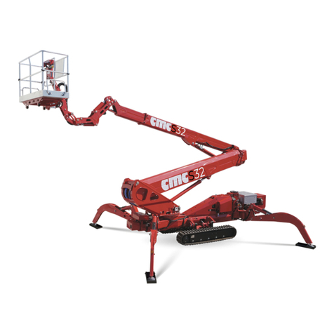
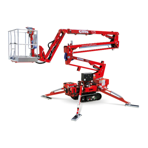
CMC S28 User manual

Mobile Elevating Work Platform(MEWP)
S28
USE AND MAINTENANCE MANUAL
Man.243 Rev.5

MAN.243 Rev.5 ENG - Use and maintenance manual S28 page 1of 138

MAN.243 Rev.5 ENG - Use and maintenance manual S28 page 1of 138
Introduction
hank you for the trust you have showed us
buying a C.M.C. mobile elevating work platform
(MEWP). We are sure you will be pleased with your
choice.
0.1 Content of the manual
This manual is added to the sold machine and contains
the instructions for its transfer, use and maintenance.
While drawing up this manual, we took into
consideration all the operations that are part of a
normal use and regular maintenance of the machine.
So, for a correct and optimum use, you have to follow
the described instructions carefully.
This manual has been drawn up in order to:
❑describe the use of the machine;
❑show the main specifications of the machine;
❑provide with the instructions for the
positioning and use of the machine;
❑describe the safety devices;
❑point out the potential risks and/or possible
dangerous situations;
❑provide with the necessary instructions for
the ordinary operations of maintenance;
❑provide with instructions for filling of the
check register.
THE USE AND MAINTENANCE MANUAL IS
CONSIDERABLE AS A PART OF THE
MACHINE. In case of the MEWP sale, please
send this manual to the new owner.
T

MAN.243 Rev.5 ENG - Use and maintenance manual S28 page 2of 138
LEGEND OF SYMBOLS USED IN THIS
MANUAL:
(CAUTION) = it warns the user about the risk
of serious damages to people or to part of the
equipment or the machine, if you do not obey the safety
regulations.
(WARNING) = it notifies the possibility of
minor injuries to people orlittle damages tothe platform
or machine parts.
(FORBIDDEN) = prohibition signal
➔(OBLIGATION) = obligation signal
(CAUTION) = it warns the user about the risk of
environmental pollution.
* (OPTIONAL) = it indicates an optional outfit.
(IMPORTANT NOTE) = it shows information and
suggestions useful to work with the MEWP.
➔This manual is addressed to:
▪users: operators, ground assistants, guard
staff, safety manager, service manager;
▪manufacturers, dealers, owners, lessors
or lessee, brokers.
0.2 Disclaimer
C.M.C. declines all responsibility in case of partial or
total non-observance of the following statements:
➔All information showed in this manual are
mandatory. Before running the machine, the user
is obliged to carefully read and study all
instructions of this manual, with particular
reference to sections relative to specific work
activity to perform. For the impossibility of the
manufacturer to be able to check the state of the
machine and the operations carried out, it is the
user's responsibility to comply of the safety
procedures described in this manual.

MAN.243 Rev.5 ENG - Use and maintenance manual S28 page 3of 138
➔Only properly trained and authorized personnel
shall be permitted to operate the MEWP. The
employer is obliged to make sure that the
operator has the aptitude requirements
necessary for the correct management of the
machine, that he has carefully read and
understood what is reported in this use and
maintenance manual, and that he has received
adequate training to work in standard and
emergency situations. However, this manual
cannot replace in any way a suitable experience
that the staff in charge must have gained
previously on similar machines or that they will be
able to get on this machine, under the guidance
of an already trained staff.
➔The user must work within the functional limits of
the machine and perform a constant and diligent
maintenance, using only original replacement
parts approved by C.M.C. Any alteration and/or
modification of the original design characteristics
of the machine without prior written approval of
the manufacturer are absolutely prohibited and
make the responsibility for such actions fall
directly on operators.
➔The operator shall carefully know the safety
standards foreseen by national and international
legislations and apply them during all operations
with the MEWP.
➔If an accident occurs (i.e. high height operator’s
suspension), it’s compulsory to replace safety
anchorage components and any damaged parts
of the machine and verify that platform’s structure
is suitable for use making it checked by C.M.C.’s
specialized technicians.
When buying a machine, a warranty certificate
is delivered with the warranty terms clearly
indicated.
The guarantee of proper testing and
functioning of the machine is strictly dependent
on the correct application of all the instructions
contained in this manual.
The non-compliance with the previous
statements automatically invalidates the
warranty.
0.3 Where and how to store the
manual
Original manufacturer's languages: Italian and English.
All other languages are copies of the original
instructions.
MAN.243 Rev.5 ENG - Use and maintenance manual S28 page 4of 138
➔The manual must be stored on the machine in
a weather-resistant storage location, in an
easily accessible place, in order to be
available for consultation at any time.
➔This manual (or its copy) must always be kept
in the best possible condition (away from
sunlight).
➔During the work, a copy shall be hold by the
ground operator in a turret case and another
copy by the basket operator inside the proper
documents case.
➔In case of loss or deterioration, the
replacement documentation must be
requested to the manufacturer, specifying the
code and the review number of the manual.
0.4 Legislative references
The machine has been designed, built and tested
according to:
othe harmonized European standard EN280
which provides the presumption of conformity
to Essential Safety Requirements of the
Machinery Directive 2006/42/EC being
Voluntary Technical Standard - type C;
othe American standard ANSI/SAIA A92.20.
The stability and overload tests of the machine were
carried out in compliance with what described in
EN280 and ANSI/SAIA A92 suite and they have been
successful.
In addition, the technical safety requirements of the
following international standards have been applied:
EN 280:2015
EN 13001-3-1
Directive
2006/42/CE
Directive
2014/35/UE
Directive
2000/14/CE
ISO 13849-1-2
ISO 3864
ISO 12100
ISO 13850
ISO 13857
ISO 20381
ISO 13854
ISO 16368
IEC 60204-1-32
ANSI/SAIA
A92.20-2020
ANSI/SAIA
A92.22-2020
ANSI/SAIA
A92.24-2018
CAN/CSA
B354.6 (2017)
CAN/CSA
B354.7 (2017)
ANSI Z359.1
AS NZS
1418.10-2011
+ A1-2017

MAN.243 Rev.5 ENG - Use and maintenance manual S28 page 5of 138
0.5 Changes and integrations
The legislative references and data indicated in this
manual are those in force when the machine has been
manufactured and placed on the market.
As this manual includes both current and optional
components, you could find information not applicable
to your machine. All the photos and drawings included
in the following manual have been added to simplify the
reader's understanding. The machine in your
possession may differ in some parts from the photos
and drawings shown. In case of differences among the
basic contents of this manual and the machine, the
user is kindly asked to contact C.M.C. to receive
supplementary technical documents.
C.M.C. reserves the right to improve its products and
update their manuals (without prior notice) according to
technical and quality improvements, and to the change
of law provisions, without being anyway obliged to
intervene on the previously sold machines and on their
documents.
Modifications or additions to a MEWP shall be made
only with prior written authorization of the
manufacturer. In case the manufacturer no longer
exists, modifications to a MEWP shall be made under
the direction of an engineer with expertise in MEWPs
sector. The owner shall retain written permission and
pass it on to any subsequent owner, as applicable.
No part of this publication can be translated, modified
or reproduced (even partially) without the expressed
authorization of C.M.C. s.r.l.
Year 2021
C.M.C. s.r.l.

MAN.243 Rev.5 ENG - Use and maintenance manual S28 page 6of 138
1 Description and
purpose
1.1 Machine definition
The machine is called S28 and it is a mobile
elevating work platform (MEWP):
•machine/device intended for moving persons,
tools and material to working positions, consisting
of at least a work platform with controls, an
extending structure and a chassis (ANSI/SAIA
92.20 par. 3);
•mobile machine intended to move persons to
working positions, where they are carrying out
work from the work platform, with the intention that
persons are getting on and off the MEWP only at
access positions at ground level or on the chassis
and which consists as a minimum of a work
platform with controls, an extending structure and
a chassis (EN 280 par. 3.1).
It is forbidden to use the MEWP with
methods and/or conditions other than those
specified and approved by the
manufacturer.
1.2 Machine purpose
The MEWP S28 is a machine which enables the
operators to reach the working place when this is high
positioned.
The machine has been designed for an essentially
vertical use. It must be travelled only when it is totally
folded in the transport position.
➔The use of the machine is allowed only to
professional staff, properly trained and
specialized.
1.3 CE certification
C.M.C. s.r.l. states under its own responsibility that S28
was designed and produced in compliance with
national and European standards, and that the
machine is identical to the model submitted to control
and test for the “CE certification” by the Notified
Institute nr. 1878 - VERICERT s.r.l. - via L. Masotti, 5
- 48124 Fornace Zarattini (RA) - Italy.
A copy of the CE Certificate is attached to the manual.

MAN.243 Rev.5 ENG - Use and maintenance manual S28 page 7of 138
1.4 TÜV certification
C.M.C. s.r.l. states under its own responsibility that S28
was designed and produced in compliance with US
standards ANSI/SAIA A92.20:2020 and that the
machine is identical to the model submitted to control
and test for the “TÜV certification” by TÜV SÜD
America Inc.
TÜV SUD America Inc. is an OSHA recognized NRTL
and a Standards Council of Canada accredited
certification body.
1.5 Classification
The mobile elevating work platform (MEWP) S28
belongs to group B: the vertical projection of the area
center of the MEWP in different platform configurations
specified by the manufacturer can be outside the
tipping lines (EN 280 par. 1.4 - ANSI/SAIA A92.20 par.
3).
As for the displacement, it belongs to type 1: travelling
is only allowed with the MEWP in its transport
1
Loading cycle: a cycle starts from the access position,
continues performing the work and finishes returning to the
access position.
configuration or in the stowed position (EN 280 par. 1.4
- ANSI/SAIA A92.20 par. 3).
1.6 Loading cycles
The machine is expected to last for 40.000 loading
cycles
1
(i.e. 10 years, for 40 weeks per year, for 20
hours per week, for 5 loading cycles per hour).
Within this term of time, the machine must undergo
at least 2 (two) deep checks (structural, mechanical,
electric, elements, etc.), in case of particularly heavy
uses (frequent use at the performance limit,
particularly unfavorable environmental conditions such
as steel plants, paper mills and so on) it is better to
increase checks. Anyway, it is a good rule to have
the state of the machine checked by the
manufacturer factory or by an authorized
workshop, at least every 1500 - 2000 hours of work
or once per year.

MAN.243 Rev.5 ENG - Use and maintenance manual S28 page 8of 138
1.7 Identification plate
On the turret, there is a plate with (engraved) all the
MEWP identification data:
Picture 1: identification plate (fac-simile).

MAN.243 Rev.5 ENG - Use and maintenance manual S28 page 9of 138
2 Specifications
2.1 Technical sheet
PERFORMANCE
Max. work height
27,90 m
91.54 ft
Min. work height
-6,70 m
21.98 ft
Max. work outreach
(with 80 kg)
14,00 m
45.93 ft
Max. work outreach
(with 140 kg)
13,00 m
42.65 ft
Max. work outreach
(with 230 kg)
11,50 m
37.73 ft
Max. load on the basket
230 kg
507 lb
Jib movement
90°
Turret rotation
+/-200° (tot. 400°
continuous)
Basket rotation
+/-90°
Max. slope to stabilize
32°/62%
Max. slope approach angle with
tracks widened (front/rear)
13°-17°/23%-31%
Max. slope approach angle with
tracks narrowed (front/rear)
7°-10°/12%-18%
Max. slope to travel
(longitudinally/transversally)
19°-8°/34%-14%
Max. chassis inclination
1°
Travel speed
0,5 - 2,4
km/h
0.3 - 1.5
mph
BASKETS
Basket height
1,10 m
3.61 ft
Standard basket:
Two-men aluminum
m
1,70x0,70
ft
5.58x2.30
*Optional baskets:
Two-men aluminum
One-man aluminum
Two-men fiberglass
One-man fiberglass
m
1,20x0,70
0,80x0,60
1,40/1,20x0,60
0,80x0x60
ft
3.94x2.30
2.62x1.97
4.59/3.94x1.97
2.62x1.97
DIMENSIONS
Total length with
basket
6,80 m
22.31 ft
Length with basket
support rotated
(without basket)
6,10 m
20.01 ft
Height in transport
configuration
(with tracks
narrowed/widened)
1,99/2,19 m
6.54/7.19 ft
Total width
(without basket)
0,90 m
2.95 ft

MAN.243 Rev.5 ENG - Use and maintenance manual S28 page 10 of 138
Clearance from the
ground in transport
configuration
(with tracks
narrowed/widened)
0,17/0,32 m
0.56/1.05 ft
Clearance under tracks
with machine stabilized
1,05 m
3.44 ft
Tracks (L x w)
1,75 x 0,25 m
5.74 x 0.82 ft
Tracks widening
0,89/1,40 m
2.92/4.59 ft
Tracks lifting
0,18/0,33 m
0.59/1.08 ft
STABILIZATION AREA
Outrigger spread length in
wide stabilization area
6,67 m
21.88 ft
Outrigger spread width in
wide stabilization area
4,43 m
14.53 ft
Outrigger spread length in
narrow stabilization area
5,22 m
17.13 ft
Outrigger spread width in
narrow stabilization area
2,67 m
8.76 ft
Outrigger spread width in
mixed stabilization area
3,63 m
11.91 ft
Outriggers foot diameter Ø
0,24 m
0.79 ft
WEIGHT AND PRESSURES
Total weight
(standard equipment)
4150 kg
9150 lb
(R) Max. pressure on the
foot
5,84 kg/cm²
(57,23 N/cm²)
83.06 lb/in2
(S) Max. pressure on the
track
0,28 kg/cm²
(2,72 N/cm²)
3.98 lb/in2
(T) Max. pressure in
travel
772 kg/m²
(7,57 KN/m²)
158 lb/ft2
(U) Max. pressure in work
(wide outrigger setup)
146 kg/m²
(1,43 KN/m²)
29.90 lb/ft2
(V) Max. pressure in work
(narrow outrigger setup)
213 kg/m²
(2,09 KN/m²)
43.63 lb/ft2
(Z) Max. pressure in work
(one side wide, one side
narrow)
172 kg/m²
(1,69 KN/m²)
35.23 lb/ft2

MAN.243 Rev.5 ENG - Use and maintenance manual S28 page 11 of 138
POWERS
Standard
hydraulic feed
1) Diesel engine:
Kubota D902-E4B, 16.1 kW (21.6 HP),
3200 rpm
*Optional
feeds
2) Electric engine
230/110/120 V
3) Electric motor G0901306, 9 kW, 48 V,
with lithium batteries 200 Ah
4) Hybrid motor (diesel + lithium batteries)
Fuel tank
capacity
30 l
Max values allowed according to USA/EU standards
Max. lowering and lifting speed
of the MEWP
0,4 m/s (1.31 ft/s)
Max. boom extension and
retraction speed
0,4 m/s (1.31 ft/s)
Max. turret rotation speed
0,7 m/s (2.3 ft/s)
Max. manual force in the basket
with 1 operator
400 N
Bolts
Size
Tightening torque
Slewing ring
M16 cl 10.9
28 daNm
Geared motor
M16 cl 10.9
28 daNm

MAN.243 Rev.5 ENG - Use and maintenance manual S28 page 12 of 138

MAN.243 Rev.5 ENG - Use and maintenance manual S28 page 13 of 138
2.2 Work diagram
Picture 2a: work diagram
(valid only in the work area set by the outriggers
placement).

MAN.243 Rev.5 ENG - Use and maintenance manual S28 page 14 of 138
Picture 2b: work areas.

MAN.243 Rev.5 ENG - Use and maintenance manual S28 page 15 of 138
2.3 Description of the main components
Picture 3: MEWP main components.

MAN.243 Rev.5 ENG - Use and maintenance manual S28 page 16 of 138
2.3.1 Frame
The frame 1 (Picture 3) is a structure in quality steel, able
to equally divide the equipment’s weight when the
MEWP is in transport position. The frame has 4 oil-
pressure jack beams for stabilization [2 front stabilizer
cylinders 2 (Picture 3), 2 rear stabilizer cylinders 3
(Picture 3)]. The basis for the bearing 4is placed on the
frame (Picture 3). It enables the swinging of the
equipment through the turn-table.
2.3.2 Turret
The turret 5(Picture 3), in quality steel, is secured to the
bushing (bearing). A hydraulic engine, with brake
normally closed, constrained to the turret, allows the
rotation of the superstructure.
2.3.3 First telescopic boom group
The first telescopic boom group 6(Picture 3) is
composed by three elements: a fixed boom and two
extendable booms.
The extension (or withdrawal) of the telescopic boom is
given by operating the “telescopic boom extension
cylinder”.
The movement of the boom (lifting and lowering) is given
by the lifting hydraulic cylinder. Such cylinder is secured
to the turret (cylinder side) and to the fixed boom (piston
side) and is supplied with safety valves.
2.3.4 Second telescopic boom group
The second telescopic boom group 8(Picture 3) is
hinged to the first telescopic boom by a rod 7(Picture 3).
The telescopic boom is composed by three elements:
one fixed boom hinged to the rod and two extendable
booms.
The extension (or withdrawal) of the telescopic boom is
given by operating the “telescopic boom extension
cylinder”.
The lifting (or lowering) of the telescopic boom is given
by operating the “lifting cylinder of second telescopic
boom group”.

MAN.243 Rev.5 ENG - Use and maintenance manual S28 page 17 of 138
2.3.5 Jib
At the end of the second telescopic boom is hinged a
boom named Jib 10 (Picture 3). The lifting or descent of
the Jib is done by operating the “Jib lifting cylinder”.
2.3.6 Basket
the basket 11 (Picture 3) is in aluminum tubulars and has
a lateral opening to allow the entrance of the operators.
The lateral opening is automatically shuttered and built
to avoid accidental openings. The basket has
anchorages for safety belts, a guardrail 1,1 m high from
the basket floor, an intermediate guardrail and a foot
protecting band along all sides of the platform. The floor
is in antiskid and auto-draining aluminum. The basket is
connected to a support 9 (Picture 3) through which it is
coupled with the jib.

MAN.243 Rev.5 ENG - Use and maintenance manual S28 page 18 of 138
3 Command stations
3.1 Machine switching on/off
station
Picture 4: engine switch on/off station.
The main electric box (Picture 4), located on the right
side of the frame, provide:
•the IK ignition key: through it, it is possible to turn
on the electric system and start the endothermic
engine;
•the green light 5indicating system power supply: it
is on when the AM key is in position 1;
•the red light 4which signals low pressure to the
engine oil;
•the red light 3which monitors coolant level;
•the orange light 2indicating the spark plugs
working;
•the red light 1which signals an alternator failure;
•the emergency bypass BP under the yellow cap
(see par.4.6.2);
•the activation lever of remote connection under the
red cap (see par.8.16.1);
•the hourcounter;
•the 24 V socket;
•the red activation button of electropump*.
3.1.1 Ignition of the endothermic engine
In order to start the endothermic engine, turn the IK
ignition key all the way to the right up to the symbol .
IK
5
4
3
2
1
BP
Other manuals for S28
1
Table of contents
Other CMC Boom Lift manuals