CMF Power Select User manual
CUSTOM METAL FABRICATORS, INC.
Installation / Operation Instructions
Power Select
Ver. 3.0
(For serial # 80396 and above)
(PLC VERSION 4.87)

Installation / Operation Instructions
CMF Power Select Ver. 3.0
REV 6.31
Table of Contents
Chapter 1 Introduction......................................................................... 2
Chapter 2 Installation.......................................................................... 3
Chapter 3 Operation............................................................................ 8
Chapter 4 Advanced HMI Operations................................................. 11
Chapter 5 Integration ......................................................................... 13
Chapter 6 Maintenance...................................................................... 23
Chapter 7 Troubleshooting................................................................. 24
Chapter 8 Drawings ........................................................................... 27

Installation / Operation Instructions
CMF Power Select Ver. 3.0
REV 6.32
1 Introduction
1.1 The CMF Power Select is a semi automatic hydro-electric positioning system for the CMF
"TH" (Turn Head), “HH” (Head House), and “Pendulum” series distributors. The heart of
this system is a micro PLC (Programmable Logic Controller) that controls and tracks the
movement and location of the inner spout. The PLC accepts input from the operator via
a 3.5” touch screen HMI (Human Machine Interface) at the operator panel.Once a
position is selected by the operator, the PLC compares the destination to the current
location and determines a direction of travel selecting the shortest route on full round
models. At this point, the PLC engages the hydraulic system and raises the inner spout.
Once the inner spout is raised, it then rotates to the position selected by the operator and
lowers into the outlet stub. The CMF Power Select incorporates several operation,
safety, and diagnostic routines into the programming to inform the operator of the current
status via the HMI at the operator panel.
1.2 From a controls standpoint, all of the CMF series distributors are identical. This allows
for simple integration of multiple units at the same facility.The following sections
describe how to install various configurations of the Power Select and how to operate and
maintain the system.
1.3 This version of the Power Select has multiple options for controlling and monitoring the
unit. The default setup uses a standard Ethernet connection directly from the HMI to the
Power Select. Other options include, but are not necessarily limited to:
•Controlling the Power Select without the HMI
•Connecting the Power Select and HMI to an Ethernet network for remote
monitoring / control
•Controlling more than one Power Select using only one HMI (the HMI can be
easily programmed for multiple units and scaled with the touch of a button)
•Other connections (see section 5)
Note: Any configuration other than the default 1:1 connection will require connections through
an Ethernet switch. The recommended max length of any single run of Ethernet is 320’
although it has been known to function without issues at longer distances. One way to easily
add more length to Ethernet is to install an unmanaged switch at the first 320’ and continue from
there.

Installation / Operation Instructions
CMF Power Select Ver. 3.0
REV 6.33
2 Installation
2.1 The CMF Power Select can be ordered as a complete unit factory installed on a new
distributor, or by itself to be retrofit to an existing “TH” distributor installation in the field.
Section 2.2 details a factory prepared unit. Section 2.3 details a field installation.
2.2 Factory Installed Unit
2.2.1 Upon receipt of the distributor, check for visible signs of damage that may have
occurred during shipment. These include scratched paint, dented housing, oil
leaking from the unit, etc.
2.2.2 Hang the distributor making sure that all outlet spouts are adequately supported to
prevent distortion of the distributor housing.
2.2.3 Mount the operator panel in the desired location. Connect the communication wire
between the operator panel and the main panel (located on the Power Select).
Shielded CAT5e cable is recommended for this connection. See dwg 502950-E
for details. Observe all applicable codes for control installations.
2.2.4 Connect the power supply wires to the terminals provided in the main panel and
the operator panel.See electrical schematics for details.
2.2.5 Turn power on to the unit and the operator panel.
2.2.6 Installation is complete; proceed to section 3, Operation.

Installation / Operation Instructions
CMF Power Select Ver. 3.0
REV 6.34
2.3 TH Series Field Installation
2.3.1 Upon receipt of the Power Select, check for visible signs of damage that may have
occurred during shipment. These include scratched paint, dented housing, oil
leaking from the unit, etc.
2.3.2 Remove the current distributor control device and install the provided adaptor into
the inner spout support pipe (dwg 503003-F). The adaptor MUST be welded to
the support pipe. DO NOT drill a hole through the adaptor and use a bolt to
attach the adaptor. A bolted adaptor would allow too much “play” in the inner
spout and the unit would not function properly. The existing hole in the support
pipe is for manual control only (i.e. cable control). If required, the inner spout
support pipe can be unbolted and removed from the distributor to weld the adaptor
in place.
2.3.3 Remove the access covers from the Power Select.
2.3.4 Locate and drill (4) 7/16” diameter holes in the bottom of the distributor using the
supplied dimensions (dwg 503003-F), or use the Power Select frame as a
template.
2.3.5 Raise the Power Select unit up to the bottom of the distributor, aligning the inner
spout support pipe adaptor shaft with the hollow bore and keyway in the gearbox,
making sure the square key is in place.Insert (4) 3/8 inch bolts through the holes
in the distributor bottom and through the holes located in the top of side frames on
the Power Select.
2.3.6 Thread the supplied “encoder bolt” assembly (dwg 503003-F) through the bottom
of the gear box into the support pipe adaptor and tighten.
2.3.7 Carefully slip the encoder shaft into the bolt with the flat area facing the setscrew
in the bolt head. Tighten the setscrew. Note: It is important that the encoder is
mounted properly so that it can’t slip, since this is how the PLC determines the
spout position.
2.3.8 Attach the “encoder tether” to the frame of the Power Select and to the encoder
bracket with ¼” bolts and tighten.
2.3.9 Connect the loose M12 cable to encoder. Note: This is a keyed connector. It
must be rotated properly or it will not plug in.
Installation / Operation Instructions
CMF Power Select Ver. 3.0
REV 6.35
2.3.10 Mount the operator panel in the desired location. Connect the communication
wire between the operator panel and the main panel (located on the Power
Select). Shielded CAT5e cable is recommended for this connection. See dwg
502950-E for details. Observe all applicable codes for control installations.
2.3.11 Connect the power supply wires to the terminals provided in the main panel and
in the operator panel. See electrical schematics for details.
2.3.12 Turn on power to the main panel, and the operator panel.
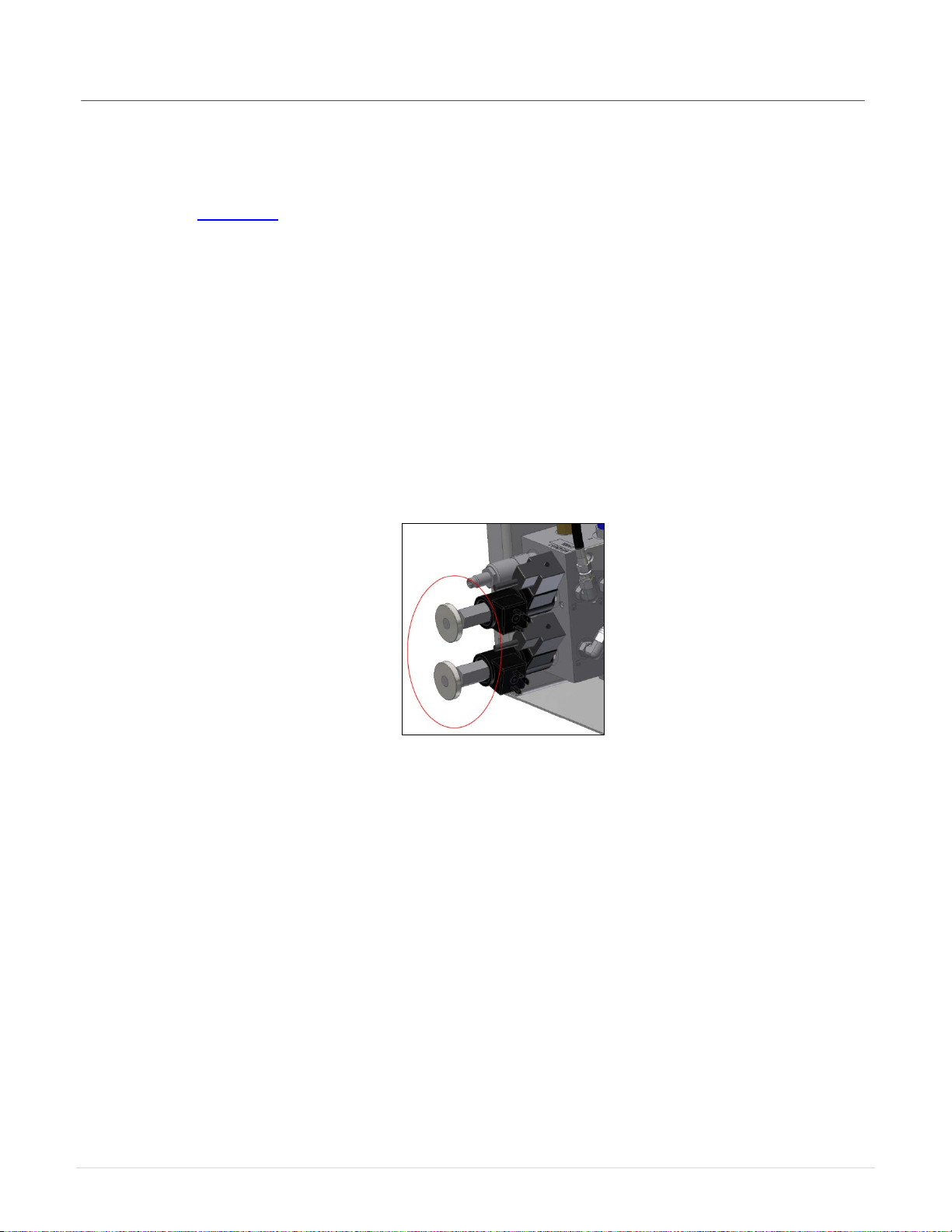
2.3.13 In order to make the adjustments needed for the system to function properly, it
will be necessary to manually operate the unit. Manually moving (jogging) the
Power Select is accomplished by starting the hydraulic pump and then pushing or
pulling the red manual override disks located on the ends of the solenoid valves.
(Fig 1) Note: You will notice that it is much easier to push the valves than to pull
them. This is normal.
Fig. 1: Solenoid Valve Override

Installation / Operation Instructions
CMF Power Select Ver. 3.0
REV 6.36
2.3.14 Remove the cover from the main electrical panel and locate the motor contactor
on the topmost terminal strip on the left side.In the center of the motor contactor
is a blue manual override switch. Slide this manual override to the left to engage
the contactor. (Fig 2) As long as this override is held, the hydraulic pump will run,
supplying hydraulic pressure to the system. With the pump running, use the
solenoid valve override controls to move the inner spout as outlined in the
previous section. Be sure that the inner spout is all the way UP before
rotating.
Fig. 2: Motor Contactor
2.3.15 With the lift cylinder retracted (down position), check the position of the down
proximity sensor. If needed, adjust the down proximity sensor block to a point
where the LED light on the sensor comes on and the block completely covers the
face of the sensor with a maximum 1/16” gap between the sensor and the block.
(Fig. 3) Note: Intrinsically safe sensors are opposite meaning the light will come
on when the sensor leaves the block, and the light will go off when the sensor is
in front of the block.
Fig. 3: Proximity Sensors
2.3.16 Jog the Power Select (UP) until the lift cylinder is fully extended (up position),
check the up proximity sensor as outlined above.

Installation / Operation Instructions
CMF Power Select Ver. 3.0
REV 6.37
2.3.17 Jog the Power Select (ROTATING) until the inner spout is aligned with the
number one outlet (dwg 503003-G). Jog the inner spout (DOWN) until the lift
cylinder is fully retracted (down position). Ensure that the inner spout has
engaged the locator ring and the outlet stub.
2.3.18 It is now time to “teach” the PLC the position of each stub outlet. Section 4.1
describes this procedure. At this point it is recommended to read through section
3, Operation, before continuing the setup procedure.
2.3.19 After teaching the outlets, installation is complete; refer to section 3 for normal
operation.
Installation / Operation Instructions
CMF Power Select Ver. 3.0
REV 6.38
3 Operation
3.1 Operator Panel
3.1.1 The operator panel consists of an electrical enclosure and the HMI
(Human Machine Interface). The HMI is a touch screen interface that allows the
operator to interact with the machine.
3.1.2 To navigate the HMI, there are buttons displayed on the screen. To activate a
button, simply touch it lightly. Some buttons have a built in delay. Delay-type
buttons must be touched and held for 1 second before the action will execute.
There are also textboxes to display and input data. Just like a button, touch the
textbox to edit the value. The “CMF” logo at the bottom of the screen with either
take you to the “MENU” screen, or back to the “HOME” screen depending on what
screen is currently displayed. Touch the banner at the top of the screen at any
time to view messages.
3.2 Power Up
3.2.1 After the unit is installed, and power is turned on to the main panel and the
operator panel, the HMI will boot to the “Welcome” screen.
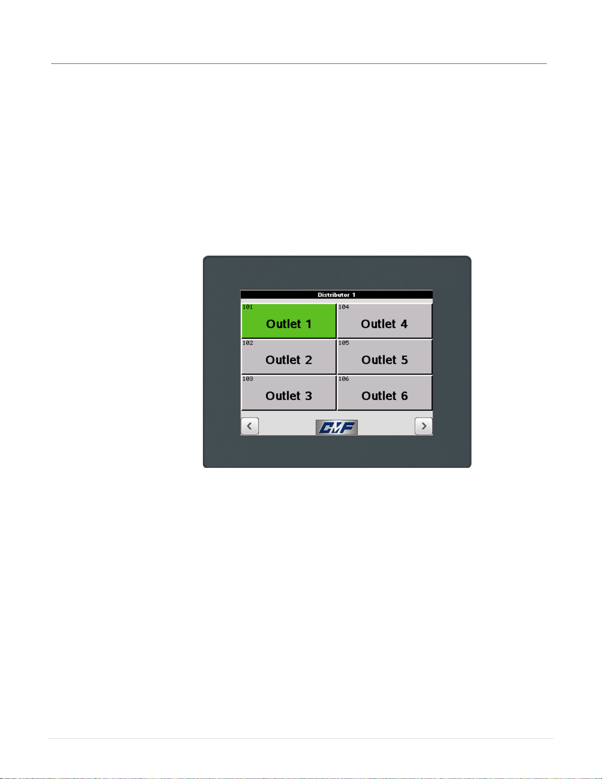
3.2.2 Once the operator closes the welcome screen, the HMI will display the “Home”
screen (Fig 4). From the “Home” screen, the operator can see the current position
of the inner spout(s) and access other screens by interacting with the buttons.
Fig. 4: Home screen
Installation / Operation Instructions
CMF Power Select Ver. 3.0
REV 6.39
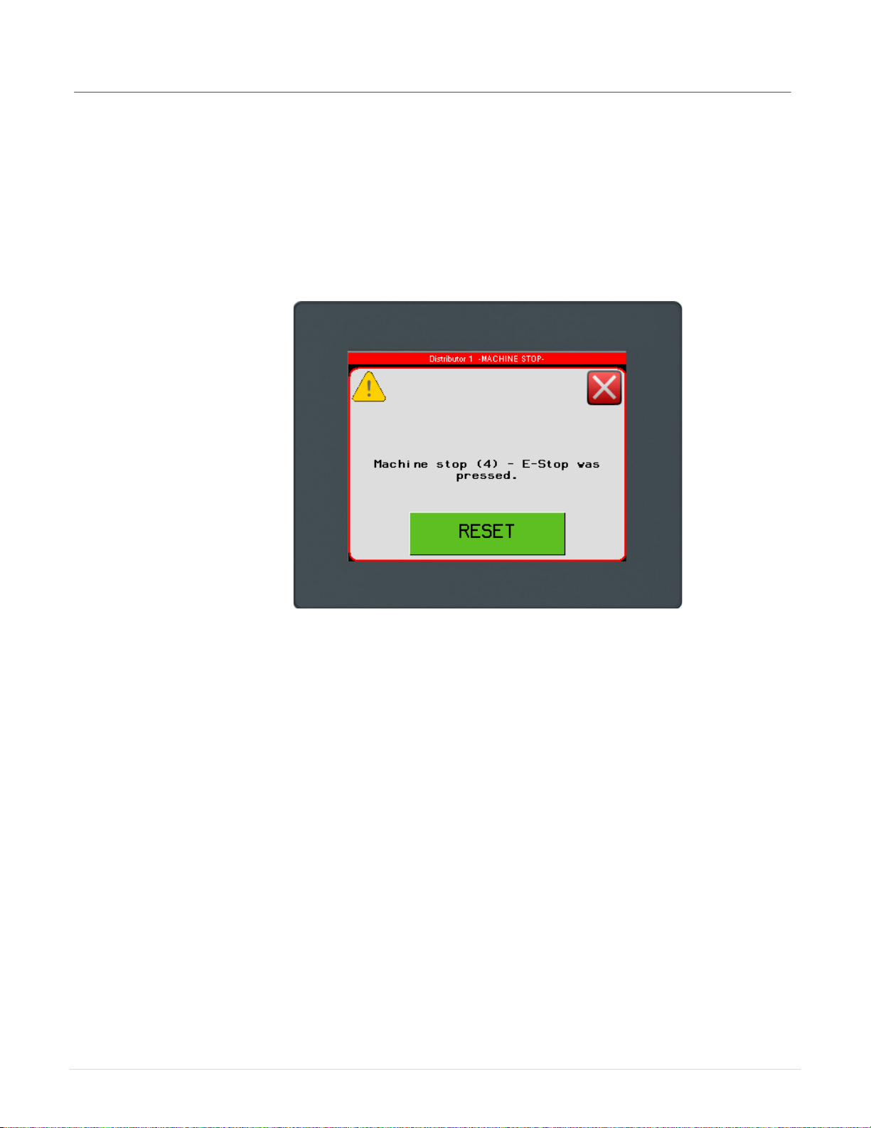
3.2.3 If the machine is booting up for the first time, or if any fault has occurred, the
operator may see the “Machine Stop” alarm banner and a popup window with
pertinent information about the fault. If the “Fault Code” popup is not visible, but
the alarm banner is being displayed at the top of the screen, the operator can
touch the banner to display the fault code.
Fig. 5: Alarm/Fault Code
Installation / Operation Instructions
CMF Power Select Ver. 3.0
REV 6.310
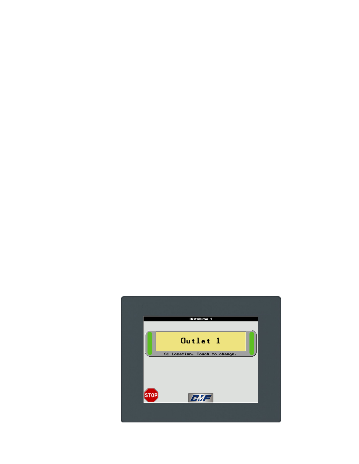
3.3 Selecting an Outlet
3.3.1 To change the position of the spout, press the button on the “Home” screen that
corresponds to the spout you want to move.
3.3.2 From the “Outlet Selection” screen (Fig. 6), choose the outlet number that the
spout should move to and press the button for at least 1 second. This delay
acts as an interlock to keep from accidentally changing the outlet. After the button
is pressed, the “moving” indicator will appear on the screen. When the inner spout
has reached its destination, the button for the corresponding outlet will turn green
and the “moving” indicator will disappear.
Fig. 6: Outlet Selection screen
Installation / Operation Instructions
CMF Power Select Ver. 3.0
REV 6.311
4 Advanced HMI operations
4.1 Logging In
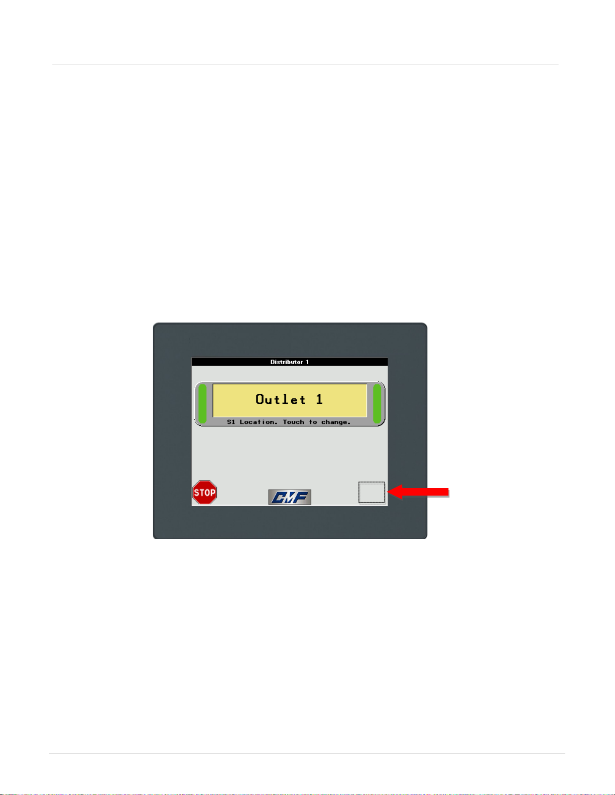
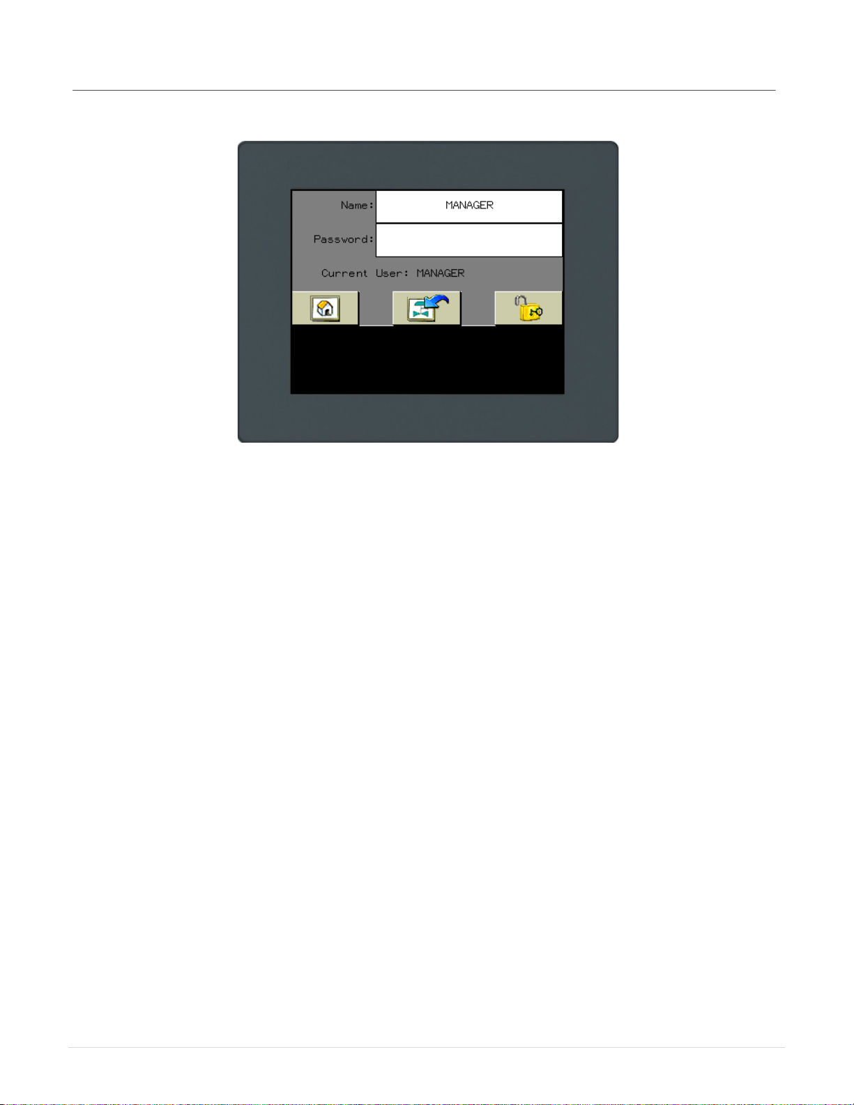
4.1.1 For advanced setup and maintenance, the operator must “Log In”. From the
“Home” screen, touch and hold in the lower right hand corner of the screen until
the “Login” screen is displayed (about 3 seconds). Touch the “Name” textbox and
type the word “MANAGER” in upper case, and then press the “Enter” button.
Touch the “Password” textbox and type the word “CMF” in upper case. Touch the
“padlock” icon to login and confirm that the “Current User” field has changed to
“MANAGER”. Touch the “home” icon to return.
Fig. 7: Invisible Button
Installation / Operation Instructions
CMF Power Select Ver. 3.0
REV 6.312
Fig. 8: Login Screen
4.1.2 After successfully logging in, a button will show up on the “Home” screen. Use it
to enter the “Setup” screen.

Installation / Operation Instructions
CMF Power Select Ver. 3.0
REV 6.313
4.2 Teaching Outlets
4.2.1 In order for the PLC to direct the spout to the proper outlet, it is required to “teach”
each position and store these set points into memory.
4.2.2 From within the “Setup” screen, touch the “Maintenance Mode” checkbox to
disable the machine automation.
4.2.3 Confirm that the “Number of Outlets” textbox matches the number of outlets on the
distributor.
4.2.4 Touch the setup button for the spout being configured. For example, on a single-
spout distributor, touch the “S1 Setup” button.
4.2.5 With the inner spout seated in the number one outlet as instructed in section
2.3.17. Touch and hold the “Set Home Position” button until the “Shaft Position”
textbox displays the new value. The default “home” position of the encoder is
“45”. This procedure changes the offset of the encoder so that the current inner
spout position is the starting point for all other positions.Note: The encoder reads
a value from 0-4096. The encoder shaft position is NOT the same thing as the
distributor outlet number. For example, with the inner spout at outlet #2, the
encoder shaft position might be at a value of 170.
4.2.6 Touch the “Teach Outlets” button.
4.2.7 Each outlet has a unique system identifier. For instance, (Inner Spout 1: Outlet 1)
is labeled “H101”. Or (Inner Spout 2: Outlet 10) is labeled “H210”.
4.2.8 In order to “teach” the current outlet as “position one”, either touch and hold the
“H101” button until the corresponding value changes or touch the textbox and
enter the value manually. Jog the inner spout to the next outlet as described in
section 2.3.
4.2.9 Repeat the procedure from section 4.2.8 for the remaining outlets, confirming that
each outlet has a unique value, and that these values increment from smallest to
largest. Note: The values must be in order with each one being larger than the
last. There can be no duplicate values. For example, (45, 170, 295, 420, 545,
670) is an acceptable range. None of the values should be “0”.
4.2.10 Touch the “Backup to HMI” button. This will store the data in the HMI in case the
PLC would ever need to be replaced. Touch the “Backup PLC” button. This will
store the data in the PLC persistent memory area.
4.2.11 Touch the “Log Out” button.
4.2.12 Configuration is complete. Refer to section 3 for normal operation.

Installation / Operation Instructions
CMF Power Select Ver. 3.0
REV 6.314
5 Integration
5.1 If required, the power select can be controlled by 3rd party hardware. There are 4 options
available for communicating with the on board PLC.
1. Modbus RTU (serial)
2. Modbus TCP/IP (Ethernet)
3. Ethernet/IP (CIP)
4. Cam switch / Relay control (24vdc signals)
5.2 Modbus Parameters
•Baud rate: 19200
•Data Bits: 8 (RTU)
•Parity Bits: none
•Stop Bit: 2
•Response Timeout: 200ms
•Time Between Frames: 3ms
•@ node address 1
5.3 Supported Modbus Requests
5.3.1
Function
Description
3 (3h)
Read multiple internal registers %MW
6 (6h)
Write single holding register %MW
16 (10h)
Write multiple registers %MW
23 (17h)
Read/Write multiple registers %MW
For more information on Modbus, refer to www.modbus.org

Installation / Operation Instructions
CMF Power Select Ver. 3.0
REV 6.315
5.4 Required Memory Objects
Address
Symbol
Description
Access
%MW1 S1_OUTLET_SELECT
Spout 1 outlet select. Set this MW to the corresponding
outlet position (101-130) to change the position of the
spout.
READ/WRITE
%MW30 FAULT_CODE
Fault code for diagnostics. Gets reset by the system
with “RESET”.
READ ONLY
%MW31
RESET
Set to “1” to reset the machine.
READ/WRITE
%MW33 MAINTENANCE_MODE
Set to “1” to bypass automation and allow for manually
moving the inner spouts. Gets reset by the system
with “RESET”.
READ/WRITE
%MW35 E_STOP
Set to “1” to disable the machine. Gets reset by the
system with “RESET”.
READ/WRITE
%MW43 S1_AT_DESTINATION
Spout 1 is at its destination and in the hole. Gets set
to “1” by the system when the condition is true.
READ ONLY

Installation / Operation Instructions
CMF Power Select Ver. 3.0
REV 6.316
5.5 Optional/Advanced Memory Objects
*These values should only be modified during setup of the machine. Check all values before attempting to
run the machine.
Address
Symbol
Description
Access
%MW0 CONTROL_TYPE
Type of input control. 0, 1, or 2 Gets set by sending
“RESET” from respective device. Set to “3”
Manually for “Modbus / Other”.
(CMF / HMI = ”0”, Ethernet/IP = ”1”, Cam/Relay =
”2”, Modbus / Other = “3”).
READ/WRITE
%MW5
NUM_INNERSPOUTS
Total number of inner spouts.
READ/WRITE
%MW6 NUM_OUTLETS
Total number of outlets. Set this MW to match the
number of outlets on the distributor.
READ/WRITE
%MW7 DISTRIBUTOR_TYPE
Type of distributor. (Flat Back= ”1”, Full Round= ”2”,
Pendulum= ”3”, Head House= ”4”).
READ/WRITE
%MW32 MACHINE_STOP
Gets set to “1” by the system if a fault has occurred.
Gets reset by the system with “RESET”.
READ ONLY
%MW60 MOVING
Gets set to “1” by the system when machine is
moving.
READ ONLY
%MW67 HEARTBEAT
Toggles from “0” to “1” every 1 second. Can be
used with a timer to confirm the presence of the
machine on the bus.
READ ONLY
%MW101-n
H101-H1n (“n” = # of
outlets on the distributor)
Spout 1 outlet positions: Used to store the unique
position of each outlet. READ/WRITE

Installation / Operation Instructions
CMF Power Select Ver. 3.0
REV 6.317
5.6 Ethernet
5.6.1 The default network parameters for the Ethernet connection are shown below.
These parameters can be changed by connecting the PLC to a switch/hub and
entering the IP address in a standard web browser such as Google Chrome or
Mozilla Firefox. If a switch is not available, a 1:1 connection can be established
with a computer provided the computers IP address is set to static and configured
to use the same subnet mask as the PLC.
5.6.2 Default network parameters
PLC IP address: 192.168.1.51
HMI IP address: 192.168.1.50
Subnet mask: 255.255.255.0
5.6.3 Changing the PLC network parameters
Enter the current IP address of the PLC in the web browser address bar. Enter
the username and password. Username: USER Password: USER. Once
logged in, browse to the “Maintenance” tab and click “Post Conf” on the left side of
the page. You can now edit the network parameters. Be very careful when editing
the post file and double check your entry before clicking on the “Save” button. For
the new settings to take effect, a power cycle of the PLC is required.
Fig. 9: PLC login

Installation / Operation Instructions
CMF Power Select Ver. 3.0
REV 6.318
Fig. 10: PLC network settings
Note: Notice the parameters are separated by commas and NOT periods. The file will be
ignored if periods are used. For the new settings to take effect, a power cycle of
the PLC is required.

Installation / Operation Instructions
CMF Power Select Ver. 3.0
REV 6.319
5.6.4 Changing the HMI network parameters
In order to modify the HMI network parameters, the user must login as
“MANAGER” to the HMI. This process is described in section 4.1.1. After logging
in, from the “Home” screen of the HMI, touch the CMF logo at the bottom of the
screen to enter the “Menu” screen. Touch the “Network Settings” button. To
modify the local network settings for the HMI, touch the “This HMI Network
Settings” button. To modify which unit/s that this HMI can communicate with,
touch the “Equipment To Control” button. If you changed the IP address of the
PLC, you have to update this parameter in the HMI in order to establish
communication to the new PLC address. Note: You cannot change the actual
IP address of the PLC from the HMI. This must be done within the PLC web
interface as outlined in section 5.6.3, or with a script on an SD card.
Table of contents
Popular Industrial Equipment manuals by other brands

Meanwell
Meanwell UHP-200A Series manual

Alfalaval
Alfalaval T6 BZM instruction manual

TigerStop
TigerStop TigerCrossCut installation guide

Black Hawk Automotive
Black Hawk Automotive Porto-Power B65139 Operating instructions & parts manual

Strack
Strack PowerMax SN5650-PMU-0330 operating instructions

Haufftechnik
Haufftechnik HSD100 EW 1x24-44+4x7-12 b40 installation instructions


DryAIR
DryAIR MAXCOIL HEFA 600 MAX Operator's manual

woodmizer
woodmizer E10 Safety, Operation, Maintenance & Parts Manual

KEBCO
KEBCO COMBISTOP 28 Installation

Delta
Delta DVP-ES2 Operation manual

Ebmpapst
Ebmpapst W2E200-HK86-01 operating instructions

Wesco
Wesco DM-800-HR-MDT Operating instructions and parts manual