Ditch Witch 410SX Installation instructions
410sx - SUPPORT 1
SERIAL NUMBER
410sx - SUPPORT 1
SERIAL NUMBER
SUPPORT
SERIAL NUMBER
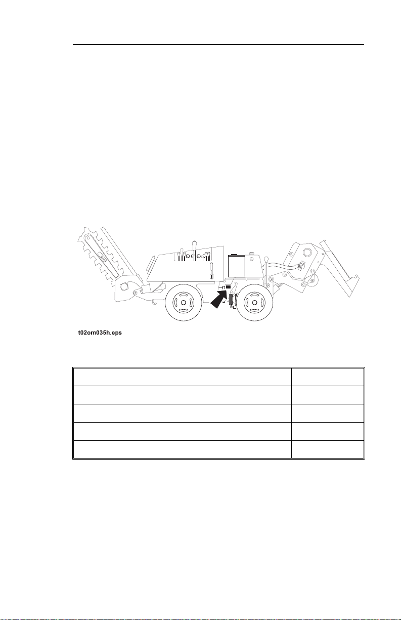
Record the serial number and date of purchase in spaces
provided. Serial number is located on rear section near
articulation joint.
Date of manufacture:
Date of purchase:
Serial number:
Engine serial number:
Trenching attachment serial number
SUPPORT
SERIAL NUMBER
Record the serial number and date of purchase in spaces
provided. Serial number is located on rear section near
articulation joint.
Date of manufacture:
Date of purchase:
Serial number:
Engine serial number:
Trenching attachment serial number

2410sx - SUPPORT
SUPPORT PROCEDURE 2410sx - SUPPORT
SUPPORT PROCEDURE
SUPPORT PROCEDURE
Notify your dealer immediately of any malfunction or failure of
Ditch Witch equipment.
Always give model, serial number, and approximate date of
equipment purchase. This information should be recorded and
placed on file by owner at time of purchase.
Return damaged parts to dealer for inspection and warranty
consideration.
Order genuine Ditch Witch replacement or repair parts from your
authorized Ditch Witch dealer. Use of another manufacturer's
parts may void warranty.
RESOURCES
Publications
Contact your Ditch Witch dealer for publications and videos
covering safety, operation, service, and repair of your equipment.
Ditch Witch Training
For information about on-site, individualized training, contact your
Ditch Witch dealer.

410sx - SUPPORT 3
INTENDED USE
410sx - SUPPORT 3
INTENDED USE
INTENDED USE
This unit is designed for operation in temperatures typically
experienced in excavation and construction work environments.
Provisions may be required to operate in extreme temperatures.
Contact your Ditch Witch dealer. Use in any other way is
considered contrary to the intended use.
EQUIPMENT MODIFICATION
This equipment was designed and built in accordance with
applicable standards and regulations. Modification of equipment
could mean that it will no longer meet regulations and may not
function properly or in accordance with the operating instructions.
Modification of equipment should only be made by competent
personnel possessing knowledge of applicable standards,
regulations, equipment design functionality/requirements, and
any required specialized testing.

4410sx - SUPPORT 4410sx - SUPPORT

410sx - FOREWORD 5
410sx - FOREWORD 5
FOREWORD
This manual is an important part of your equipment. It provides
safety information and operation instructions to help you use and
maintain your Ditch Witch equipment.
Read this manual before using your equipment. Keep it with the
equipment at all times for future reference. If you sell your
equipment, be sure to give this manual to the new owner.
If you need a replacement copy, contact your Ditch Witch dealer.
If you need assistance in locating a dealer, visit our website at
www.ditchwitch.com or write to the following address:
The Charles Machine Works, Inc.
Attn: Marketing Department
PO Box 66
Perry, OK 73077-0066
USA
The descriptions and specifications in this manual are subject to
change. The Charles Machine Works, Inc. reserves the right to
improve equipment. Some product improvements may have
taken place after this manual was published. For the latest
information on Ditch Witch equipment, see your Ditch Witch
dealer.
Thank you for buying and using Ditch Witch equipment.
Other manuals for 410SX
1
Table of contents
Other Ditch Witch Industrial Equipment manuals


