Tolomatic BC3 Series User manual

Tolomatic • URL: http://www.tolomatic.com • Email: [email protected] • Fax: (763) 478-8080 • Toll Free: 1-800-328-2174
BC3 Series™ Band Cylinder® Wedge Style
BC320/BC3M(M)20 2"/50mm BORE
16
17
18
15
14
13
1
2
345
78910
12
11
6
26
28
32
36
38
25
39
40
41
35 34
29
30
33
27
42
20
19
22
24
21 23
37 31
NOTE: Items shaded cannot be field installed
without proper assembly fixtures. For repair,
return cylinder to Tolomatic, Inc.
Replaced 3420-4004
Parts Listing
ITEM
BC320
PART NO. or
CONFIG. CODE
BC3M(M)20
PART NO. or
CONFIG. CODE
DESCRIPTION QTY.
12,4 NSBBC320 NSBBC3M20
NSBBC3MM20
Replacement Sealing
Band (3420-1005) 1
22,4 NDBBC320 NDBBC3M20
NDBBC3MM20
Replacement Dust Band
(3420-1028) 1
3 3420-1030 Lower Clamp 2
4 3420-1045 Upper Clamp Pad 2
5 3420-1029 Upper Clamp 2
6 3415-1455 4410-1017 Set Screw 4
710920-1029 4920-1029 Pipe Fitting 10
81
3420-1007 – Standard Head 2
– 4420-1007 Metric Taper Head 2
– 5420-1007 Metric Parallel Head 2
91,2,3 0701-1003 Buna-N O-Ring 2
1 Items available as Standard Head Assembly #3420-9001, Metric Taper Head Assembly #4420-9001 and Metric Parallel Head Assembly #5420-9001.
COMMON REPLACEMENT PARTS:
2 Repair Kit: Parts contained in Repair Kit RKBC320SK_ _ _
3 Seal Kit: Parts contained in Seal Kit #3420-9019
4 After configuration code add: SK_ _ _ (note: the letters SK indicate stroke, follow these letters with the stroke length in decimal inches.) If the actuator
has the dual carrier option add the code DW_ _ _ (note: follow the letters DW with the distance between the carriers in decimal inches.)
ITEM
BC320
PART NO. or
CONFIG. CODE
BC3M(M)20
PART NO. or
CONFIG. CODE
DESCRIPTION QTY.
1010920-1018 Cushion Needle 2
112,3 0920-1061 Buna-N O-Ring 2
122,3 0920-1028 U-Cup 2
13 0920-1087 4920-1047 Tapped Screw 8
1411004-1073 4915-1002 Pipe Plug
1510769-1059 4910-1002 Pipe Plug 2
162,3 1001-1021 1001-1021 Buna-N O-Ring 3
172, 3 0920-1011 Wear Ring 2
18 3420-9000 Piston/Bracket
Assembly w/magnet 1
19 3420-1023 Rail way 2
202, 3 0920-1027 Cushion Seal 2
21 3420-1013 BC320 Nut AR
22 3420-1506 Machined Tube 1
234NMBBC320 NMBBC3M20
NMBBC3MM20
Replacement Magnet
Band (3420-1022) 2
24 3420-1495 Machined Wedge 1
25 0605-1045 Socket Head Cap Screw A/R
262, 3 3420-2024 End Cap 2
Parts Sheet
3420-4005_11_BC320ps

TOLOMATIC • URL: http://www.tolomatic.com • Email: [email protected] • Fax: (763) 478-8080 • Toll Free: 1-800-328-2174
Parts Sheet #3420-4005_11_BC320ps
2 – Parts Listing BC320, BC3M20
16
17
18
15
14
13
1
2
345
78910
12
11
6
26
28
32
36
38
25
39
40
41
35 34
29
30
33
27
42
20
19
22
24
21 23
37 31
Parts Listing
Drawing repeated for reference
NOTE: Items shaded cannot be field installed
without proper assembly fixtures. For repair,
return cylinder to Tolomatic, Inc.
ITEM
BC320
PART NO. or
CONFIG. CODE
BC3M(M)20
PART NO. or
CONFIG. CODE
DESCRIPTION QTY.
27 3420-2022 Carrier Cover 1
28 3420-1019 Ball Return Tube 2
29 2317-1014 4415-1000 Socket Head Cap Screw 4
30 3415-1059 3415-1059 Washer 8
31 3420-1009 Ball 92
322,3 3420-1025 BC320 Wiper 2
33 3420-2021 4420-1235 Machined Carrier 1
34 3420-1014 Ball Return 2
35 3420-1015 Right Ball Race 2
36 3420-1032 Left Ball Race 2
37 3420-1069 PLT, Ball Return 2
ITEM
BC320
PART NO. or
CONFIG. CODE
BC3M(M)20
PART NO. or
CONFIG. CODE
DESCRIPTION QTY.
38 3420-1010 4420-1010 Piston Block 2
39 1085-1075 0610-1033 Socket Head Cap Screw 2
40 3415-1047 Upper Band Ramp 2
41 3420-1024 Carrier Way 2
42 0605-1046 4415-1001 Socket Head Cap Screw A/R
1 Items available as Standard Head Assembly #3420-9001, Metric Taper Head Assembly #4420-9001 and Metric Parallel Head Assembly #5420-9001.
COMMON REPLACEMENT PARTS:
2 Repair Kit: Parts contained in Repair Kit RKBC320SK_ _ _
3 Seal Kit: Parts contained in Seal Kit #3420-9019
4 After configuration code add: SK_ _ _ (note: the letters SK indicate stroke, follow these letters with the stroke length in decimal inches.) If the actuator
has the dual carrier option add the code DW_ _ _ (note: follow the letters DW with the distance between the carriers in decimal inches.)

TOLOMATIC • URL: http://www.tolomatic.com • Email: [email protected] • Fax: (763) 478-8080 • Toll Free: 1-800-328-2174
Parts Sheet #3420-4005_11_BC320psParts Sheet #3420-4005_11_BC320ps BC320, BC3M20 Dual 180° Carrier Option – 3
24
25
19
40
23
2
43
26
38
34
27
57
58
59
60
56
35 36
39
32
42
33
31
28
50
63
64 52
53
51
55
61
41
54
62
Parts Listing
4 After configuration code add: SK_ _ _ (note: the letters SK indicate stroke, follow these letters with the stroke length in decimal inches.) If the actuator
has the dual carrier option add the code DW_ _ _ (note: follow the letters DW with the distance between the carriers in decimal inches.)
ITEM
BC320D
PART NO. or
CONFIG. CODE
BC3M(M)20D
PART NO. or
CONFIG. CODE
DESCRIPTION QTY.
24NDBBC320 NDBBC3M20
NDBBC3MM20
Replacement Dust Band
(3420-1028) 1
19 3420-1023 3420-1023 Rail Way 2
23 NMBBC320 NMBBC3M20
NMBBC3MM20
Replacement Magnet
Band (3420-1022) 2
24 3420-1020 3420-1020 Machined Rail 2
25 3420-1008 4420-1008 Rail Nut AR
26 3420-2024 3420-2024 End Cap 2
27 3420-2022 3420-2022 Carrier Cover 1
28 3420-1019 3420-1019 Ball Return Tube 2
31 3420-1009 3420-1009 Ball 92
32 3420-1025 3420-1025 Wiper 2
33 3420-2021 4420-1235 Machined Carrier 1
34 3420-1014 3420-1014 Ball Return 2
35 3420-1015 3420-1015 Right Ball Race 2
36 3420-1032 3420-1032 Left Ball Race 2
38 1085-1075 0610-1033 Socket Head Cap Screw 2
39 3415-1047 3415-1047 Upper Band Ramp 2
40 3420-1077 4415-1018 Socket Head Cap Screw AR
41 3420-1069 3420-1069 PLT Ball Return 2
42 3420-1024 3420-1024 Carrier Way 2
43 0605-1046 4415-1001 Socket Head Cap Screw 4
ITEM
BC320D
PART NO. or
CONFIG. CODE
BC3M(M)20D
PART NO. or
CONFIG. CODE
DESCRIPTION QTY.
50 3420-1049 4420-1049 Plate, Conn., Dual
Carrier 2
51 0920-1093 4415-1019 Socket Head Cap Screw 8
52 3420-1054 4420-1054 Plate, Dual Carrier 1
53 0920-1093 4415-1019 Socket Head Cap Screw 8
54 2317-1015 4920-1025 Socket Head Cap Screw 4
55 3420-1053 3420-1053 Tube Support 1
56
3420-1051 4420-1051 Head, Dual 180° 2
5420-1051 Head, Dual 180°,
Parallel Port 2
57 3420-1050 3420-1050 PLT, Band, Dual 180°
Carrier 2
58 1004-1066 4515-1019 Socket Head Cap Screw 4
59 3420-1029 4420-1029 Clamp, Upper 2
60 3415-1455 4410-1017 Set Screw 4
61 3420-1013 4420-1013 Nut 4
62 3415-1219 3415-1219 Set Screw 2
63 1009-1065 4415-1019 Socket Head Cap Screw
(each side) 2
64 3420-1052 3420-1052 Foot Mount, Dual 180°
Carrier 1

TOLOMATIC • URL: http://www.tolomatic.com • Email: [email protected] • Fax: (763) 478-8080 • Toll Free: 1-800-328-2174
Parts Sheet #3420-4005_11_BC320ps
4 – Instructions BC320, BC3M20
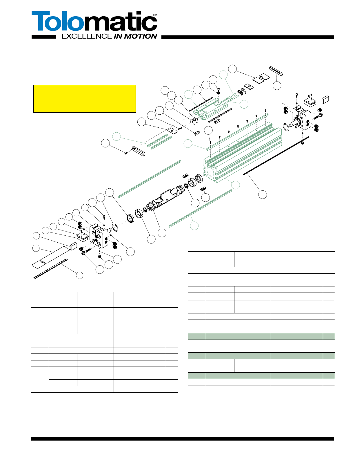
CYLINDER DISASSEMBLY INSTRUCTIONS FOR INSTALLATION OF
REPAIR KITS ONLY
1. Remove Band Cylinder from machinery.
2.
Remove any foot mounting hardware external shock absorbers or
switches if present. Remove the four Head Screws(13) and the two
Set Screws(6) from each cylinder Head(8). Remove the Upper Clamp
Pad(4), Upper Clamp(5) and Lower Clamp(3). Remove Heads.
3. Remove Screws(42) from End Caps(26) and slide End Caps off
Carrier(33). Slide off Carrier Cover(27). Remove top Dust Band(2).
Remove Screws(29) to release Piston Blocks(38). Slide Carrier(33)
slightly either direction to remove Piston Blocks(38) and release
Piston Bracket Assembly(18). Slide Piston Bracket Assembly out
end of tube.
CAUTION: DO NOT remove the Carrier or the rails. Ball Bearings
will fall out as a result.
4. Dislodge the inner Sealing Band(1) from its groove by gently press-
ing down on the band with an O-ring Pick or similar tool.(When
doing so, take care that NO SCRATCHES are made in the tube
bore slot.) Remove Sealing Band.
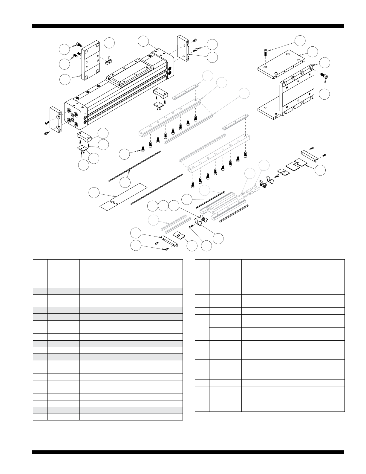
CYLINDER ASSEMBLY INSTRUCTIONS
1. CLEAN AND LUBRICATE
Thoroughly clean all components, particularly the tube bore slot and
bands. Thoroughly lubricate the tube with Magnalube®-G grease.
2. READY INNER SEALING BAND
Lubricate rubber strip on both sides of new Sealing Band(1) with
Magnalube®-G grease. Slide Sealing Band(1) into cylinder
Tube(22) with rubber portion facing up. Center band in Tube so
equal lengths of Band extend out both ends.
CAUTION: Metal edges of Sealing Band are sharp. Exercise caution
to avoid injury to yourself of the Band and Tube when inserting.
3. INSTALL PISTON ASSEMBLY
Lubricate and install new U-Cups(12)(lip seals facing out) onto
Piston ends(18). Lubricate and install new Cushion
Seals(20)(small end facing out) into Piston ends and rotate to seat
them in their grooves.
NOTE: If the cylinder will be used with optional shock absorber
packages, do not install the Cushion Seals. Doing so will adversely
affect shock performance.
Lubricate and install new Wear Rings(17) onto the piston with the
thinner edge and widest part of the flat inward, lining up the wider
flat portion with the band ramp and the narrower flat portion with
the flat on the Piston. Place a small amount of grease into the
Cushion Seals on each end of the Piston. Fill indentations on both
sides of the Piston Bracket Assembly(18) completely with grease
and install into the cylinder Tube(22) feeding the Sealing Band(1)
between the Piston and Bracket. If the cylinder is equipped for
switches, it is important to note which side of the Piston Bracket
Assembly(18) contains the Magnet, as switches must be attached
to that side of the Tube. Slide the Piston Bracket Assembly(18) to
the Carrier(33), slide the Carrier back over the Piston and continue
to move the Piston Bracket Assembly the length of the tube to seat
the sealing band in its groove. Wipe away excess grease.
NOTE: If Tube and Piston were greased properly, excess grease
should be present as Piston exits end of tube.
4. TRIM SEALING BAND
With a razor blade, remove rubber from extended band until flush
with the end of tube. With tin snips, trim band to length indicated.
Cylinder Size Trim Length From Tube
2"(50 mm) 1.200" (30.48 mm)(Tolerance of +/- .032")
CAUTION: Bands inaccurately cut too long may cause serious
injury to your hand when pressing the head onto the tube.
5. INSTALL HEADS
Lubricate and install new O-Rings(11) onto Head snouts. Lubricate
and install new O-rings(16) into cross ports on Heads(8). Remove
Cushion Needle Valve(10) and lubricate and install new O-Rings(9)
onto Cushion Needle Valves. Insert Cushion Needle Valves(10)
back into Heads(8). Insert heads into tube using a slight rocking
motion. DO NOT TWIST. Twisting the head during installation may
cut the O-ring resulting in excessive leakage during operation.
NOTE: When inserting heads, make sure band does not get
pushed backwards into tube. Rubber on band must remain flush to
the tube after head installation.
Install Head Bolts(13) into heads(8). Torque Head Bolts(13) to
180-195 in.-lbs(20.34-22.03 Nm).
6. LUBRICATE BALLWAYS
Before installing the top Dust Band(2) lubricate the ballways with
Mobil HP grease.
7. INSTALL CARRIER STOPS
Place a Piston Stop(38) on either side of the Piston Bracket
Assembly(18), notch on Stop to face bracket. Slide the Carrier(33)
over the Piston Bracket and Carrier Stops(38) until holes in the
Carrier line up with holes in Piston Stops. Apply Loctite #242 on the
Screws(29) and secure stops to the carrier. There should be no
slack between stops and bracket.
8. INSTALL DUST BAND
Install the top Dust Band(2) over the Carrier(33) centering it along
the length of the cylinder. Slide Carrier Cover(27) into slots on top
of Carrier. Apply Loctite #242 to Screws(42) and secure End
Caps(26) to ends of Carrier(33). With tin snips, cut ends of top
band 1/16" in from outside edge of Head(8). Place a Lower
Clamp(3) between the Sealing Band(1) and Dust Band(2). Place
Upper Clamp Pad(4) and Upper Clamp(5) in each Head(8). Apply
Loctite #242 to Set Screws(6) and insert in Upper Clamp(5).
Torque set screws to 20-30 in.-lbs. to secure bands.
9. CHECK ASSEMBLY
Run the Carrier(33) back and forth along the full stroke to make
certain the cylinder is properly assembled before applying air.
Before mounting cylinder back in application, check the cylinder’s
internal cushions.(If optional shock absorber kits are being used,
this step can be eliminated as Cushion Seals(20) were not
installed.) Push the Carrier(33) to one end. You should feel the
Cushion decelerate the Carrier before the Cushion bottoms out. If
the Carrier slams into the end of the cylinder, either the Cushion
Seals have not been properly installed or the Cushion Needle
Valve(10) is adjusted too far out.
10. REMOUNT
Before installing back in application, check your air lines to be sure
they are in good condition and free of leaks. Remount and apply air.
If external shock absorbers are not being used, readjustment of the
Cushions may be necessary. Start by screwing the Cushion Needle
Valve(10) all the way in but do not tighten, then back it out slightly.
Cycle the cylinder and back the Cushion Needle Valve out as nec-
essary to reduce the amount of cushion. This will prevent the load
from slamming into an under adjusted cushion and prevent band
damage caused from pressure spikes as a result of over tightening
the Cushion Needle Valve.

BC320, BC3M20 Options – 5
TOLOMATIC • URL: http://www.tolomatic.com • Email: [email protected] • Fax: (763) 478-8080 • Toll Free: 1-800-328-2174
Parts Sheet #3420-4005_11_BC320psParts Sheet #3420-4005_11_BC320ps
70 71
72
73
61
52 51
50
53
68
67
65
66
69 60
55
SHOCK
MOUNT KIT
SWITCH KIT
FOOT MOUNT KIT
TUBE
SUPPORT
KIT
SHOCK STOP
PLATE KIT
Switch Ordering NOTES:
To order field retrofit switch and hardware kits for all Tolo-
matic actuators: SW (Then the model and bore size, and type
of switch required)
Example: SWBC320RT
(Hardware and Form A Reed switch with 5 meter lead for 2.0"
bore BC3 band cylinder)
Service Parts Ordering NOTES:
1Shock Stop Plate Kit contains shock plate,
impact bolts, screws and dowel pins.
2Foot Mount Kit contains one bracket and
mounting hardware.
3Shock Mount Kit Without Shock contains
one set of mounting hardware.
4Shock Mount Kit With Shock contains one
shock absorber and mounting hardware.
5Tube Support Kit contains one tube support
and mounting hardware.
ITEM
BC315
PART NO. BC3M(M)15
PART NO.
DESCRIPTION QTY.
SHOCK STOP PLATE KIT1
KIT13420-9004 4420-9004 Shock Stop Plate Kit
50 3420-1057 4415-1003 Impact Bolt 2
51 3420-1039 4420-1039 Shock Plate 1
52 1009-1065 4415-1019 Socket Head Cap Screw 4
53 0610-1044 0610-1044 Dowel Pin 2
SWITCH KIT
55
CONFIG. CODE ORDERING
Mounting Hardware & FE conn. included
CODE
DESCRIPTION
BT
Switch Kit, Reed, Form C, 5m
BM
Switch Kit, Reed, Form C, Male Conn.
RT
Switch Kit, Reed, Form A, 5m
RM
Switch Kit, Reed, Form A, Male Conn.
CT
Switch Kit, Triac, 5m
CM
Switch Kit, Triac, Male Conn.
KT
Switch Kit, Hall-effect, Sinking, 5m
KM
Switch Kit, Hall-effect, Sinking, Male Conn.
TT
Switch Kit, Hall-effect, Sourcing, 5m
TM
Switch Kit, Hall-effect, Sourcing, Male Conn.
NOTE: When ordered female connector & all mounting hardware is included
FOOT MOUNT KIT2
KIT23420-9005 4415-9095 Foot Mount Kit (one end)
KIT23420-9025 4420-9025 Dual 180° Carrier Foot Mount Kit
(one end)
60 3420-1052 Foot Mount 2
61 1009-1065 4415-1019 Socket Head Cap Screw 4
SHOCK MOUNT KIT WITHOUT SHOCK3
KIT33420-9003 4420-9003 Shock Mount Kit - one side
(hardware only, no shock)
65 1004-1064 4420-1002 Socket Head Cap Screw 4
67 3420-1038 4420-1038 Clamping Hook 2
68 3420-1037 4420-1037 Shock Mount 1
SHOCK MOUNT KIT WITH SHOCK4
KIT43420-9010 4420-9010 Shock Absorber Kit - one side
(Light Duty Shock)
KIT43420-9013 4420-9013 Shock Absorber Kit - one side
(Heavy Duty Shock)
65 1004-1064 4420-1002 Socket Head Cap Screw 4
66 0920-1068 4920-1068 Shock, Light Duty 1
0920-1069 4920-1069 Shock, Heavy Duty 1
67 3420-1038 4420-1038 Clamping Hook 2
68 3420-1037 4420-1037 Shock Mount 1
69 0512-1018 0520-1018 Shock Stop Spacer 1
TUBE SUPPORT KIT5
KIT53420-9006 4420-9006 Tube Support Kit AR
KIT53420-9026 4420-9026 Dual 180° Carrier Tube Support
Kit AR
70 2307-1018 4415-1011 Socket Head Cap Screw 4
71 3415-1046 4415-1014 Flat Head Cap Screw 4
72 3420-1013 4420-1013 BC315 Nut 4
73 3420-1044 3420-1044 Tube Support 2
74 3420-1017 4420-1017 Tube Support Nut 2

Parts Sheet #3420-4005_11_BC320ps
6 – Options BC320, BC3M20
TOLOMATIC • URL: http://www.tolomatic.com • Email: [email protected] • Fax: (763) 478-8080 • Toll Free: 1-800-328-2174
Parts Sheet #3420-4005_11_BC320ps
SINGLE-END PORTING
The BC3 Band Cylinder is uniquely designed for multiple port locations
including single-end porting. The lower ports on the head assembly only
function when used to cross port the cylinder for single-end porting.
To convert the BC3 cylinder to a single-end port:
1. Remove access Pipe Plug fitting(14) from the opposite head
assembly that air lines will be installed into. Then remove the internal
port Pipe Plug(15).
2. Reinstall access Pipe Plug(14) into the bottom of Head(8).
3. Remove pipe plug(7) from head where air lines will be installed.
NOTE: Use thread sealant when installing pipe plugs.
OPTIONAL ACCESSORY ASSEMBLY INSTRUCTIONS
1. SHOCK ABSORBERS
Slide a Clamping Hook(67) into each side of the Tube(21). Apply
Loctite #242 to Screws(65) and secure Shock Mount Plate(68) to
Clamping Hooks(67). Torque Screws(65) to 100-110 in.-lbs.
Thread Shock(66) into Shock Mount Plate(68). Tighten Shock(66)
to Shock Mount Plate(68) with Jam Nut. Apply Loctite #242 to
Screws(52) and secure Shock Plate(51) to Carrier(32). Insert two
Dowel Pins(53) into Shock
Plate(51). Apply Loctite #242 to Impact
Bolts(50) and thread into holes in ends of Shock Plate(51). Torque
Impact Bolts(50) to 100-110 in.-lbs.
2. FOOT MOUNTS
Apply Loctite #242 to Screws(61) and secure Foot Mount(60) to
each Head(8).
3. TUBE SUPPORTS
Two T-Nuts(74) are required on the bottom of Tube(22) and two
T-Nuts(72) in the lower slots on tube sides. Tube Supports should
be secured at the required distances determined for the application
to prevent Tube deflection. Apply Loctite #242 to Screws(71) and
secure Tube Supports(73) to tube aligning holes in T-Nuts with
holes in Tube Supports.
4. SWITCHES
On assembled cylinder, Secure Switch to open port side of cylinder
with a Hardware kit(clamp and screw).
NOTE: Form A Reed Switches should not be used in TTL logic cir-
cuits. A voltage drop caused by the L.E.D. indicator will result.For
applications where TTL circuits are used, please contact the factory.
WARNING: An ohmmeter is recommended for testing Reed
Switches. NEVER use an incandescent light bulb as a high current
rush may damage the switch.
Reed and TRIAC switches are only recommended for signalling
position, not directly powering soleniods. For shifting a solenoid, a
relay or resistor is recommended between it and the Reed Switch.
Switch ratings must not be exceeded at any time.
NOTE: For Hall Effect Switch Magnet, be sure the S pole of the
magnet(indicated with black dot) is facing toward the
switch(down).
For complete Switch Performance Data, refer to the Tolomatic
Pneumatic Products Catalog # 9900-4000.
Main
Port
Cross
Port
Main
Port
Cross
Port
Main
Port
Cross
Port
Standard Porting
(cross ports not functional)
Ported From Left Side
Pipe Plug
removed
Pipe Plug
inserted
Ported From Right Side
Plugged
Open
Pipe Plug
inserted
Pipe Plug
removed
Main
Port
Cross
Port
Main
Port
Cross
Port
Main
Port
Cross
Port
PORTING CONFIGURATIONS
70 71
72
73
61
52 51
50
53
68
67
65
66
69 60
55
SHOCK
MOUNT KIT
SWITCH KIT
FOOT MOUNT KIT
TUBE
SUPPORT
KIT
SHOCK STOP
PLATE KIT
Drawing repeated for reference

Parts Sheet #3420-4005_11_BC320ps
BC320, BC3M20 Options – 7
Parts Sheet #3420-4005_11_BC320psParts Sheet #3420-4005_11_BC320ps
Band Cylinder® is a registered trademark and BC3 Series is a trademark of Tolomatic, Inc.
Loctite® is a registered trademark of the Loctite Corporation, www.loctite.com
Magnalube®-G is a registered trademark of the Carleton-Stuart Corporation, www.magnalube-g.com
Mobil grease® HP is a registered trademark of Mobil Oil Corporation, www.mobil.com
LUBRICATION AND MAINTENANCE
All Tolomatic BC3 Band Cylinders are prelubricated at the factory. To
ensure maximum cylinder life, the following guidelines should be followed.
1. Filtration
We recommend the use of dry, filtered air in our products. “Filtered
air” means a level of 10 Micron or less. “Dry” means air should be
free of appreciable amounts of moisture. Regular maintenance of
installed filters will generally keep excess moisture in check.
2 External Lubricators(optional)
The factory prelubrication of Tolomatic Band Cylinders will provide
optimal performance without the use of external lubrication. However,
external lubricators can further extend service life of pneumatic actua-
tors if the supply is kept constant.
Oil lubricators,(mist or drop) should supply a minimum of 1 drop per
20 standard cubic feet per minute to the cylinder. As a rule of thumb,
double that rate if water in the system is suspected. Demanding con-
ditions may require more lubricant.
If lubricators are used, we recommend a non-detergent, 20cP @ 140˚F
10-weight lubricant. Optimum conditions for standard cylinder opera-
tion is +32˚ to +150˚F(+0˚ to 65.5˚C).
NOTE: Use of external lubricators may wash away the factory installed
lubrication. External lubricants must be maintained in a constant sup-
ply or the results will be a dry actuator prone to premature wear.
3. Sanitary environments
Oil mist lubricators must dispense “Food Grade” lubricants to the
air supply. Use fluids with ORAL LD50 toxicity ratings of 35 or high-
er such as Multitherm® PG-1 or equivalent. Demanding conditions
can require a review of the application.
4. Bearing lubrication
The bearing system is prelubricated at the factory with Mobil HP
grease. Relubrication is recommended every .5-1 million cycles
using a lithium-soap base grease for optimal bearing performance.
To relubricate, remove Set Screws(6), Upper Clamp(5) and Upper
Clamp Pad(4). Lift back Dust band(2) and apply grease directly to
the stationary ball ways.
5. Cushion Adjustment
Adjust the cushion needles in the cylinder heads carefully to obtain a
smooth, hesitation free deceleration for your particular application. If
there are questions on proper adjustment, please consult Tolomatic.
3800 County Road 116, Hamel, MN 55340 USA
http://www.Tolomatic.com • Email: Help@Tolomatic.com
Phone: (763) 478-8000 • Fax: (763) 478-8080 • Toll Free: 1-800-328-2174
© 2021 Tolomatic 202101131437
All brand and product names are trademarks or registered trade-
marks of their respective owners. Information in this document is
believed accurate at time of printing. However, Tolomatic assumes
no responsibility for its use or for any errors that may appear in
this document. Tolomatic reserves the right to change the design
or operation of the equipment described herein and any associated
motion products without notice. Information in this document is
subject to change without notice.
Visit www.tolomatic.com for the most up-to-date technical information
PERFORMANCE
THE NOTCHED
FACE OF THE
SWITCH INDICATES
THE SENSING
SURFACE AND
MUST FACE
TOWARD THE
MAGNET.
THE NOTCHED
GROOVE IN THE
ACTUATOR
INDICATES THE
GROOVE TO
INSTALL THE
SWITCH. CONTACT
TOLOMATIC IF
SWITCHES ARE
REQUIRED ON
ANOTHER SIDE OF
ACTUATOR.
0
50
100
150
200
0100 200 300 400 500
VOLTAGE A.C. or D.C.
CURRENT D.C (mA)
REED FORM A
R
E
E
D
F
O
R
M
C
TEMP. vs CURRENT, DC REED VOLTAGE DERATING, DC REEDTEMP. vs CURRENT, AC REED
0
100
200
300
400
500
600
020406080 100 120 140 160
LOAD CURRENT (mA)
OPERATING TEMPERATURE (F)
REED FORM C
REED FORM A
0
200
400
600
800
1000
020406080 100 120 140 160
LOAD CURENT (mA)
OPERATING TEMPERATURE (F)
TRIAC
RT & RM DC REED, FORM A
BT & BM DC REED, FORM C
CT & CM AC REED, TRIAC
TT & TM HALL-EFFECT, SOURCING, PNP
KT & KM HALL-EFFECT, SINKING, NPN
REED
SWITCH
LOAD
BROWN
BLUE
(-) (-)
(+) (+)
REED
SWITCH
LOAD
BROWN
BLUE
(-) (-)
(+) (+)
OR
AC
COM
LOAD
INPUT
TRIAC
SWITCH
120V
ac
Max.
MOV
BROWN
BROWN
BLUE
BLUE
REED
SWITCH
COMMON
NORMALL
Y CLOSED
NORMALLY OPEN
BROWNBROWN
BLACK
BLUE
BLUE
HALL-EFFECT
SOURCING
SWITCH
BLACK
LOAD
BROWN
BROWN
BLUE
BLUE
(-)
(+)(+)
(-)
(+)(+)
HALL-EFFECT
SINKING
SWITCH
BROWN
BROWN
BLACK
BLUE
BLUE
(-)
(+)
(+)
(-)
(+)
(+)
LOAD
WIRING DIAGRAMS INSTALLATION INFORMATION
Some actuators may require switch mounting on a specific
side of the assembly. Call Tolomatic for details.
Female Connector 5M
SWITCHES
There are 10 sensing choices: DC reed, form A (open) or formC (open or
closed); AC reed (Triac, open); Hall-effect, sourcing, PNP (open); Hall-effect,
sinking, NPN (open); each with either flying leads or QD (quick disconnect).
Commonly used to send analog signals to PLC (programmable logic
controllers), TLL, CMOS circuit or other controller device. These switches are
activated by the actuator’s magnet.
Switches contain reverse polarity protection. QD cables are shielded; shield
should be terminated at flying lead end.
If necessary to remove factory installed switches, be sure to reinstall on the
same of side of actuator with scored face of switch toward internal magnet.
**
WARNING
: Do not exceed power rating (Watt = Voltage X Amperage). Permanent damage to sensor will occur.
*QD = Quick Disconnect; Male coupler is located 6" [152mm} from sensor,
Female coupler to flying lead distance is 197" [5m] also see Cable Shielding specification above
REPLACEMENT OF QD SWITCHES MANUFACTURED BEFORE JULY 1, 1997:
It will be necessary to replace or rewire the female end coupler.
CAUTION: DO NOT OVER TIGHTEN SWITCH HARDWARE WHEN INSTALLING!
CURRENT
Quick disconnect
Wiring
BROWN
BLACK
BLUE
+
-
SIGNAL
OLD
Quick disconnect
Wiring
BROWN
BLACK
BLUE
+
-
SIGNAL
†
Shielded from the female quick disconnect coupler to the flying leads. Shield should be terminated at flying lead end.
§
Maximum current 500mA (not to exceed 10VA) Refer to Temperature vs. Current graph and Voltage Derating graph
§§
Maximum current 250mA (not to exceed 3VA) Refer to Temperature vs. Current graph and Voltage Derating graph
Reed Switch Life Expectancy: Up to
200,000,000 cycles (depending on load cur-
rent, duty cycle and environmental conditions)
DC REED, AC REED (TRIAC)
AND HALL-EFFECT
QUICK-DISCONNECT
COUPLER - MALE END
QUICK-DISCONNECT
COUPLER - FEMALE END
SPECIFICATIONS
REED DC REED AC HALL-EFFECT DC
ORDER CODE
RT RM BT BM CT CM TT TM KT KM
LEAD 5m QD* 5m QD* 5m QD* 5m QD* 5m QD*
CABLE SHIELDING Unshielded Shielded† Unshielded Shielded† Unshielded Shielded† Unshielded Shielded† Unshielded Shielded†
SWITCHING LOGIC "A" Normally Open "C" Normally Open or Closed Triac Normally Open PNP (Sourcing) Normally
Open NPN (Sinking) Normally Open
MECHANICAL CONTACTS Single-Pole Single-Throw Single-Pole Double-Throw Single-Pole Single-Throw NO, These Are Solid State Components
COIL DIRECT Yes Yes Yes —
POWER LED None None None None None
SIGNAL LED Red Red Red
OPERATING VOLTAGE 200 Vdc max. 120 Vdc max. 120 Vac max. 5 - 25 Vdc
OUTPUT RATING — — 25 Vdc, 200mA dc
OPERATING TIME 0.6 msec max.
(including bounce)
0.7 msec max.
(including bounce) —< 10 micro sec.
OPERATING TEMPERATURE -40°F [-40°C] to 158°F [70°C] 0°F [-18°C] to 150°F [66°C]
RELEASE TIME 1.0 msec. max. — —
ON TRIP POINT — — 150 Gauss maximum
OFF TRIP POINT — — 40 Gauss minimum
**POWER RATING (WATTS) 10.0
§
3.0
§ §
10.0 5.0
VOLTAGE DROP 2.6 V typical at 100 mA NA — —
RESISTANCE 0.1 Ω Initial (Max.) — —
CURRENT CONSUMPTION —1 Amp at
86°F [30°C]
0.5 Amp at
140°F [60°C] 200 mA at 25 Vdc
FREQUENCY —47 - 63 Hz —
CABLE MIN.
BEND
RADIUS
STATIC 0.630" [16mm]
DYNAMIC Not Recommended
This manual suits for next models
3
Table of contents
Other Tolomatic Industrial Equipment manuals

Tolomatic
Tolomatic MXP63PTP User manual

Tolomatic
Tolomatic MXP25PTP User manual

Tolomatic
Tolomatic Band Cylinder BC2 Series User manual

Tolomatic
Tolomatic MXP16N User manual

Tolomatic
Tolomatic TC15 User manual

Tolomatic
Tolomatic MXP50N User manual

Tolomatic
Tolomatic BC4 Series User manual

Tolomatic
Tolomatic TC07SS Use and care manual

Tolomatic
Tolomatic PB208 User manual

Tolomatic
Tolomatic MXP32N Series Use and care manual