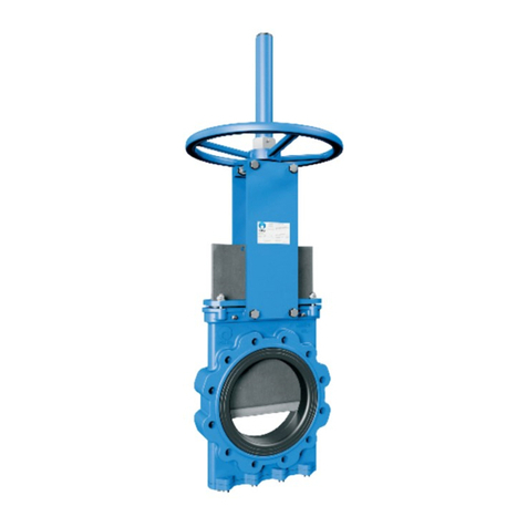
CMO VALVES UB Series Instructions for use

1manufacturing the valve you need
INSTRUCTIONS AND MAINTENANCE MANUAL - UB SERIES -
UB
Rev .00 / 19-04-2021
KNIFE GATE VALVE - SERIE UB

2manufacturing the valve you need
KNIFE GATE VALVE - SERIE UB
Rev .00 / 19-04-2021
2
INSTRUCTIONS AND MAINTENANCE MANUAL - UB SERIES -
ASSEMBLY
THE UB VALVE COMPLIES WITH THE FOLLOWING:
Machinery Directive: DIR 2006/42/EC (MACHINERY).
Pressure Equipment Directive: DIR 97/23/EC (PED) ART.3, P.3.
Potentially Explosive Atmospheres Directive (optional): DIR 94/9/EC (ATEX)
CAT.3 ZONE 2 and 22 GD.
The UB valve complies with the Directive on Equipment and Protective Systems
for Use in Explosive Atmospheres. In these cases the logo will appear on the iden-
tification label. This label shows the exact classification of the zone in which the
valve can be used. The user is responsible for its use in any other zone.
HANDLING
When handling the equipment please pay special attention to the following points:
• SAFETY WARNING: Before handling the valve, check that the crane to be
used is capable of bearing its weight.
• To prevent damage, especially to the anticorrosive protection, it is recom-
mended to use soft straps to lift the CMO valves. These straps must be fitted
around the top of body.
• Do not lift the valve or hold it by the actuator. Lifting the valve by the actuator
can lead to operating problems as it is not designed to withstand the valve’s
weight.
• Do not lift the valve by holding it in the flow passage area. The valve’s seal is
located in this area. If the valve is held and lifted by this area it can damage
the surface and the O-ring seal and lead to leakage problems whilst the valve
is operating.
• Packing in wooden boxes: If the equipment is packed in wooden boxes, these
must be provided with clearly marked holding areas where the slings will be
placed when securing them. In the event that two or more valves are pac-
ked together, separation and securing elements must be provided between
them to prevent possible movements, knocks and friction during transport.
When storing two or more valves in the same box you must ensure they are
correctly supported to prevent deformations. In the case of dispatches by
sea we recommend the use of vacuum bags inside the boxes to protect the
equipment from contact with sea water.
• Pay special attention to maintaining the correct levelling of the valves during
loading and unloading as well as during transport to prevent deformations in
the equipment. For this purpose we recommend the use of mounts or trest-
les.
INSTALLATION
In order to avoid personal harm and other types of damage (to the facilities, the valve, etc.) please follow these instructions:
• The sta responsible for the installation or operation of the equipment must be qualified and trained.
• Use suitable Personal Protective Equipment (PPE) (gloves, safety boots, goggles, etc).
• Shut o all lines that aect the valve and put up a warning sign to inform about the work being performed.
• Completely isolate the valve from the whole process. Depressurise the process.
• Drain all the line fluid through the valve.
• Use manual rather than electric tools during installation and maintenance, in accordance with EN13463-1(15)
fig. 1

3
www.cmovalves.com
KNIFE GATE VALVE - SERIE UB
Rev .00 / 19-04-2021
It is very important to make sure that the valve is correctly aligned and parallel to the flanges to
prevent leakages and avoid deformations. Ensure the valve is assembled in open position.
• The screws in the tapped blind holes will have a maximum depth P (fig. 2) and will never reach the
bottom of the hole. The following table (table 1) shows the maximum thread depth in the holes and
the maximum torque to be applied to the flange screws:
parallelism and
correct alignment
DN 50 65 80 100 125 150 200 250 300 350 400 450 500 600 700 800 900 1000 1200
P8 8 9 9 9 10 10 12 12 21 21 22 22 22 22 22 20 20 22
Table. 1
fig. 3
fig. 2
Before installation, inspect the valve to ensure no damage has occurred during transport or storage. Make sure that the inside
of the valve body and, in particular, the seal area are clean. Inspect the installation’s pipes and the flanges to make sure they are
clean.
ASPECTS TO BE CONSIDERED DURING ASSEMBLY
• The UB valve is bidirectional, meaning the direction of the fluid is not important, since it works correctly in both directions.
• Special care must be taken to respect the correct distance between the flanges and ensure they are correctly aligned and
parallel (fig. 1). The incorrect position or installation of the flanges can cause deformations on the valve’s body and this could
lead to operating problems.
• The equipment must be firmly installed in the duct. It will be joined to the duct with a screw joint.
• The screws and nuts to be fitted must also be suitable for the operating conditions and their measurements must be in accor-
dance with the approved plans. The screws and nuts must be fitted diametrically.
The torque to apply to the fastening screws and nuts must be correct according to the applicable standard; we recommend the
initial assembly be carried out with a low tightening torque and after all the screws are in place, the final torque applied.
• As regards scaolding, ladders and other auxiliary elements to be used during the assembly, follow the safety recommenda-
tions indicated in this dossier.
• Once the equipment has been assembled, make sure that there are no elements, whether interior or exterior, which can inter-
fere with the movement of the knife gate.
• Make the relevant connections (electrical, pneumatic, hydraulic) in the equipment’s actuator system following the instructions
and wiring diagrams supplied with it.
• The operation of the equipment must be coordinated with the site’s control and safety sta and no modifications are permitted
in the equipment’s external indication elements (limit switches, positioners, etc.).
• When operating the equipment, follow the safety recommendations indicated in this dossier.

4manufacturing the valve you need
KNIFE GATE VALVE - SERIE UB
Rev .00 / 19-04-2021
In horizontal pipes it is recommended that CMO valves be assembled in vertical position, although other assembly positions are
also possible.
Position number 1: This is the most advisable position.
Position number 8: The valve can be installed in this position but you are advised to contact CMO if this is necessary.
Positions 2, 3, 6 and 7: For large valves (over DN300), the maximum installation angle with the vertical is 30º. For smaller sizes
the angle can be increased up to 90º (positions 4 and 5).
When it is necessary to install large valves in any of these positions, it is recommended to consult CMO, as in these cases, due
to the weight of the actuator, a suitable support must be made to prevent deformations and operating problems in the valves.
Positions 4 and 5: For smaller sized valves, the valves can be installed in these positions.
To install larger valves (over DN300) in any of these positions, please contact CMO.
In these cases, due to the weight of the actuator, a suitable support must be made to prevent deformations and operating
problems in the valves.
ASSEMBLY POSITIONS (horizontal pipe)
fig. 5
fig. 4

5
www.cmovalves.com
KNIFE GATE VALVE - SERIE UB
Rev .00 / 19-04-2021
To operate the valve: Turn the handwheel clockwise to close or anticlockwise to open.
To operate the valve pull one of the chain’s vertical drops, taking into account that sealing is carried out when the chainwheel
turns clockwise.
First loosen the position locking clamp located on the yoke. Once it is unlocked, raise the lever to open it or lower to close it. To
complete the operation lock the lever again.
CMO pneumatic actuators are designed to be connected to a pneumatic grid of between 6 kg/cm² and 10 kg/cm².
The pressurised air used for the pneumatic actuator must be correctly dried, filtered and lubricated.
This type of actuator does not require any adjustment, due to the fact that the pneumatic cylinder is designed for the exact
stroke required by the valve.
CMO hydraulic actuators are designed to work at a standard pressure of 135 kg/cm² (other pressures can be used in accordance
with needs).
This type of actuator does not require any adjustment, due to the fact that the hydraulic cylinder is designed for the exact stroke
required by the valve.
If the valve incorporates a motorised actuator it will be accompanied with the electric actuator supplier’s instructions.
Positions 1, 2 and 3: In these positions, it is recommended to
make a suitable support, since, due to the weight of the actuator,
deformations may arise and this can lead to operating problems in
the valve.
Once the valve has been installed, check that all the screws and
nuts have been correctly tightened and that the whole valve
action system has been correctly adjusted (electrical connections,
pneumatic connections, instruments, etc).
All CMO valves are tested on site, although it is possible that the
stung box screws (in valves from DN50 to DN600) or the packing
nuts (in valves over DN600) may come loose during handling and
need to be retightened.
Once the valve is installed in the pipe and has been pressurised, it is
very important to check whether there is any leakage in the stung
box area (upper part of the body in valves from DN50 to DN600) or
the packing area (in valves over DN600).
In the event of a leakage, retighten the packing gland nuts or stung
box screws until the leakage stops, ensuring that there is no contact
between the packing gland and the through conduit.
A very high tightening torque on the packing gland nuts or stung
box screws can lead to problems, such as an increase in the torque
required to drive the valve, a reduction in the working life of the
gasket or stung box seal, or the breaking of the packing gland.
ASSEMBLY POSITIONS (vertical/leaning pipe)
HANDWHEEL (rising stem, non-rising stem and with gear box)
CHAINWHEEL
LEVER
PNEUMATIC
HYDRAULIC (double and single acting)
MOTORIZADO (husillo ascendente, no ascendente)
ACTUATOR
fig. 5
Once the valve is installed in place, check that the flanges and electrical and pneumatic connections are secure. If the valve has
electrical accessories or you are in an ATEX zone, earth connections must be made before operating it.
If you are in an ATEX zone, check the continuity between the valve and the pipe (EN 12266-2, annex B, points B.2.2.2. Ind B.2.3.1.).
Check the pipeline’s earth connection and the conductivity between the outlet and inlet pipelines.

6manufacturing the valve you need
KNIFE GATE VALVE - SERIE UB
Rev .00 / 19-04-2021
MAINTENANCE
• The sta responsible for the maintenance or operation of the equipment must be qualified and trained.
• Use suitable Personal Protective Equipment (PPE) (gloves, safety boots, goggles, etc).
• Shut o all lines that aect the valve and put up a warning sign to inform about the work being performed.
• Completely isolate the valve from the whole process. Depressurise the process.
• Drain all the line fluid through the valve.
• Use manual rather than electric tools during the maintenance, in accordance with EN13463-1(15).
The only maintenance required in this type of valves is to change the seat’s rubber seal (located between the two body halves)
and the stung box seal (in valves from DN50 to DN600) or gasket (valves over DN600). It is recommended to regularly check
the seal every 6 months, however its working life will depend on the valve’s working conditions, such as: pressure, temperature,
number of operations, type of fluid and others.
In an ATEX zone, electrostatic charges may be present inside the valve, which can cause a risk of explosion. The user will be
responsible for carrying out the appropriate actions in order to minimise the risks.
The maintenance sta must be informed about the risks of explosion and ATEX training is recommended.
If the fluid transported constitutes an internal explosive atmosphere, the user must regularly check the installation’s correct seal-
tightness.
Regularly clean the valve to prevent accumulation of dust.
Assembly is not permitted at the end of the line.
Avoid re-painting the products supplied.
CMO will not be liable if the valves suer any damage due to improper handling or without proper authorisation. The valves must
not be modified except under express authorisation from CMO.
In order to avoid personal or material damage when performing the maintenance tasks, it is recommended to follow these
instructions:
Handwheel
Pneumatic
actuator
Electric-
motor actuator
Hydraulic
actuator
Geared
handwheel
LUBRICATION
We recommend greasing the stem 2 times per year, applying grease over the entire length of the stem.
After the maintenance and in an ATEX zone, you must check the electrical continuity between the pipe and the rest of the valve’s
components, such as the body, through conduit, stem, etc. (EN 12266-2 Standard, annex B, points B.2.2.2. and B.2.3.1.).
fig. 6
Handwheel
chain Lever

7
www.cmovalves.com
KNIFE GATE VALVE - SERIE UB
Rev .00 / 19-04-2021
1. Make sure there is absolutely no pressure and fluid in the facility.
2. Remove the valve from the pipeline.
3. Remove the actuator, the through conduit (2) and the
protection devices (when fitted) from the valve, leaving just
the body.
4. Once the body has been isolated, release all the screws which
secure the two halves of the body (1).
5. Separate the two halves of the body (1) and remove the seal
joint (5). If the body is stainless steel, take care not to lose the
slides (6) fitted on the inside.
6. Clean the inside surfaces of the body, in particular the seal joint
housing.
7. Position a new compression seal (5) of the same size in the
same location as the previous one.
8. Reassemble the two body halves (1) and secure by screwing.
9. The valve assembly will be performed in exactly the opposite
way to the disassembly.
*Note: The numbers in brackets refer to the components list in Table 5 and to Table 6.
REPLACING THE SEALING JOINT
PETROLEUM JELLY
Saybolt colour ASTM D-156 15
Melting point (ºC) ASTM D-127 60
Viscosity at 100ºC ASTM D-445 5
Penetration 25ºC mm./10 ASTM D-937 165
Silicone content None
Pharmacopeia BP OK
Table. 2
*Note: During the assembly of the new sealing joint it is recommended to apply “Vaseline” to the seal to facilitate the assembly
process and the correct operation of the valve (do not use oil or grease); table 2 below shows details of the Vaseline used by
CMO.
fig. 7
IMPORTANT SAFETY ASPECTS
• In order to work under ideal safety conditions, the magnetic and electrical elements must be in idle mode and the air tanks
depressurised. The electrical control cabinets must also be out of service. The maintenance sta must be up to date with the
safety regulations and work can only start under orders from the site’s safety sta.
• The safety areas must be clearly marked and you must avoid placing auxiliary equipment (ladders, scaolding, etc.) on levers
or moving parts which may lead to the movement of the knife gate.
• In equipment with spring return actuators, the knife gate valve must be mechanically locked and only unlocked when the
actuator is pressurised.
• In equipment with electrical actuator, it is recommended to disconnect it from the mains in order to access the moving parts
without any risk.
• Due to its great importance, you must check that the valve shaft has no load before disassembling the actuator system.
Taking into account the recommendations indicated, below we indicate the maintenance operations carried out in this type of
equipment:

8manufacturing the valve you need
KNIFE GATE VALVE - SERIE UB
Rev .00 / 19-04-2021
As mentioned above, valves DN50 to DN600 have a stung box seal rather than a
gasket. Valves over DN600 do have the traditional gasket system.
• REPLACING THE STUFFING BOX SEAL (VALVES DN50 - DN600)
1. Make sure there is absolutely no pressure and fluid in the facility.
2. Remove the valve from the pipeline.
3. Remove the actuator, the through conduit (2) and the protection devices
(when fitted) from the valve, leaving just the body.
4. Once the body has been isolated, release all the screws which secure the two
halves of the body.
5. Separate the two halves of the body (1) and remove the seal joint (5) and then
the stung box seals (4) of each body half. If the body is stainless steel, take
care not to lose the slides (6) fitted on the inside.
6. Clean the inside surfaces of the body (1), in particular the seal joint housing
and the stung box seals.
7. Position new stung box seals (4) of the same size in the same location as
the previous ones.
8. Reassemble the two body halves (1) and secure by screwing
9. The valve assembly will be performed in exactly the opposite way to the
disassembly.
REPLACING THE GLAND
Note: The numbers in brackets refer to the components list in Table 4.
fig. 8
Note: During the assembly of the new stung box seals, we recommend applying Vaseline to facilitate assembly and subsequent
operation of the valve (do not use oil or grease); the characteristics of the Vaseline used by CMO are set out in Table 2.
• REPLACING THE GLAND (VALVES OVER DN600)
1. Make sure there is absolutely no pressure and fluid in the facility.
2. Place the valve in open position.
3. If the valve has safety protections, remove them.
4. Loosen the screws that connect the stem or spindle to the through conduit.
5. Loosen the connection between the support plates (7) and the body (1), and
remove the actuator.
6. Release and remove the packing gland (4).
7. Remove the gasket (3) using a pointed tool, taking care not to damage the
surface of the through conduit (2).
8. Carefully clean the gasket, making sure there are no residues anywhere so the
new gasket strips fit correctly.
9. Insert the new gasket (3). As standard, CMO valve packing comprises several
gasket lines and one rubber joint line in the middle.
10. Place the packing gland (4) in its original position, making sure it does not
touch the through conduit (2), carefully tighten all the screws crosswise and
make sure the same distance is left between the through conduit (2) and the
packing gland (4) on both sides.
11. Screw down the support plates (7) and the stem (9), in reverse order to that
described in steps 4 and 5.
12. If the valve has safety protections, return them.
13. Perform several manoeuvres with no load, checking the correct operation of
the valve and ensuring the packing gland (4) is correctly aligned.
14. Pressurise the valve in the line and tighten the packing gland (4) crosswise,
enough to prevent leakages to the atmosphere.
fig. 9
Stung
box seals Slides

9
www.cmovalves.com
KNIFE GATE VALVE - SERIE UB
Rev .00 / 19-04-2021
MAINTAINING THE PNEUMATIC ACTUATOR
The pneumatic cylinders in our valves are manufactured and assembled at our premises. The maintenance of these cylinders
is simple, if you need to replace any elements or have any questions please consult CMO. Below is an exploded diagram of the
pneumatic actuator and a list of the cylinder’s components. The top cover (5) and the support cover (2) are usually made of
aluminium, although pneumatic cylinders over Ø200 mm are made of cast iron GGG40.
The maintenance kit normally includes: the bushing (7), along with the sealing joints (8 and 9) and the scraper (6), and, if the
customer so requires, the piston (3) is also supplied. Below we show the steps to follow to replace these parts.
1. Position the valve in closed position and shut o the pneumatic circuit pressure.
2. Loosen the cylinder air input connections.
3. Release and remove the cylinder cap (5), the cylinder tube (4) and the tie rods (16).
4. Loosen the nut (14) which connects the piston (3) and the spindle (1), and remove the pieces. Disassemble the cir-clip (10) and
remove the bushing (7) with its joints (8 and 9).
5. Release and remove the cylinder head (2), in order to remove the scraper (6).
6. Replace the damaged parts with new ones and assemble the actuator in the reverse order to that described for disassembly.
PNEUMATIC ACTUATOR
POS. DESCRIPTION MATERIAL
1 SPINDLE AISI-304
2 SUPPORT COVER ALUMINIUM
3 PISTON S275JR + EPDM
4 CASING ALUMINIUM
5 UPPER COVER ALUMINIUM
6 SCRAPER NITRILE
7 BUSHING NYLON
8 EXTERIOR O-RING NITRILE
9 INTERIOR O-RING NITRILE
10 CIR-CLIP STEEL
11 WASHER ST ZINC
12 O-RING NITRILE
13 WASHER ST ZINC
14 SELF-LOCKING NUT 5.6 ZINC
15 O-RING NITRILE
16 TIES F-114 ZINC
17 WASHER ST ZINC
18 NUT 5.6 ZINC
19 SCREW 5.6 ZINC
20 WASHER ST ZINC
21 NUT 5.6 ZINC
22 SCREW A-2
23 SELF-LOCKING NUT A-2
24 PROTECTION S275JR
Table. 3
fig. 10
*Note: Numbers in parenthesis refer to de components list in table 3.

10 manufacturing the valve you need
KNIFE GATE VALVE - SERIE UB
Rev .00 / 19-04-2021
To ensure the valve is in optimum conditions of use after long periods of storage, it should be stored in a well-ventilated place at
temperatures below 30ºC.
It is not advisable, but if it is stored outside, the valve must be covered to protect it from heat and direct sunlight, with good
ventilation to prevent humidity. The following aspects must be considered for storage purposes:
• The storage place must be dry and under cover.
• It is not recommended to store the equipment outdoors with direct exposure to adverse weather conditions, such as rain,
wind, etc, even when the equipment is packaged.
• This recommendation is even more important in areas with high humidity and saline environments. Wind can carry dust and
particles which can come into contact with the valve’s moving parts and this can lead to operating diculties. The actuator
system can also be damaged due to the introduction of particles in the dierent elements.
• The equipment must be stored on a flat surface to avoid deformations.
• If the equipment is stored without suitable packaging it is important to keep the valve’s moving parts lubricated, for this
reason it is recommended to carry out regular checks and lubrication.
• Likewise, if there are any machined surfaces without surface protection it is important for some form of protection to be
applied to prevent the appearance of corrosion.
COMPONENTS LIST (manual valve DN50-DN600)
POS DESCRIPTION
1 BODY
2 THROUGH CONDUIT
3 SEAL RIM
4 STUFFING BOX SEAL
5 SEALING JOINT
6 SLIDES
7 SUPPORT PLATES
8 STEM
9 YOKE
10 STEM NUT
11 CHECK NUT
12 HANDWHEEL
13 NUT
14 HOOD
15 TOP CAP
Table. 4
STORAGE
fig. 11

11
www.cmovalves.com
KNIFE GATE VALVE - SERIE UB
Rev .00 / 19-04-2021
COMPONENTS LIST (Manual valves over DN600)
POS DESCRIPTION
1 BODY
2 THROUGH CONDUIT
3 GASKET
4 PACKING GLAND
5 SEALING JOINT
6 SLIDES
7 SUPPORT PLATES
8 STEM
9 YOKE
10 GEARED MOTOR
11 HOOD
12 TOP CAP
13 HANDWHEEL
Table. 5
fig. 12

12 manufacturing the valve you need
KNIFE GATE VALVE - SERIE UB
Rev .00 / 19-04-2021
NORTH AMERICA
SOUTH AMERICA
EUROPE
MIDDLE EAST
AFRICA
ASIA
AUSTRALIA
& OCEANIA
www.cmovalves.com
CMO MADRID
C/ Rumania, 5 - D5 (P.E. Inbisa)
28802 Alcalá de Henares
Madrid (Spain)
Tel.: (+34) 91 877 11 80
Fax: (+34) 91 879 79 94
cmomadrid@cmovalves.com
www.cmovalves.com
CMO HEADQUARTERS
MAIN OFFICES & FACTORY
Amategi Aldea, 142
20400 Tolosa
Guipuzcoa (Spain)
Tel.: (+34) 943 67 33 99
Fax: (+34) 943 67 24 40
cmo@cmovalves.com
www.cmovalves.com
CMO SOUTH AMERICA
Bodegas Mersan
Avenida Lo Espejo 01565
Pabellón 8, Local 0821-0823
Santiágo de Chile (Chile)
Tel.: (+56 2) 255 94 775
www.cmosudamerica.com
Table of contents
Other CMO VALVES Control Unit manuals
Popular Control Unit manuals by other brands

GiBiDi
GiBiDi SC380 Instructions for installation

Qcells
Qcells Q.PEAK DUO BLK ML-G10/t Series Installation and operation manual

Paradox
Paradox PCS265LTE Installation and programming guide
Heath Zenith
Heath Zenith DUAL BRITE SL-5318 user manual
Sys Tec Electronic
Sys Tec Electronic ECUcore-1021 Hardware manual
red lion
red lion Graphite GMDIO installation guide
