CMP Panther 35 LE User manual

651‐486‐2010 info@marinetechproducts.com
MODEL 35 LE
55‐0350
AUXILIARY OUTBOARD MOTOR LIFT
DESIGNED FOR RANGER [AND SIMILAR]
FISHING BOATS
This view shows the cut out on
the transom plate
REV 1/19
1.604.940.2010 | sales@cmpgroup.net

INTRODUCTION
Congratulations, you have just purchased the finest auxiliary outboard motor lift available
With proper installation and
care, this motor lift will provide you with years of trouble free use and
Please take a few moments to review the information contained in this booklet to familiarize
with the installation procedures required to successfully mount your new motor lift.
Installation is particularly when you know each step ahead of
Before using your motor lift, read the operating tips at the end of this booklet for
you should take when using your motor lift on the water and when
your
Here is a list of the tools and supplies that you will need:. Because of varying in-
stall scenarios, mounting hardware is not included.
—electric drill with 1/8” 3/16”, and 1/2” drill bits
—Two 9/16” wrenches
—Phillips head screwdriver
—-For heavier motors, a hoist to lift the motor while installing
—four 1-1/2” diameter stainless hex cap screws of the appropriate length
[for proper bolt length, see the information on the following page]
—four 1-1/2” stainless nylon insert nuts
—eight 1/2” stainless washers
—-clear RTV silicone for sealing the mounting holes
—dialectic grease for the electrical connections
—security bolts that match the clamp bracket on your motor
For proper bolt length selection see the information on the following page.

BEFORE STARTING
Selecting the Mounting position
This Panther Motor Lift is designed specifically for Ranger [and similar] Multi-Species Boats, so
that the motor can be mounted at the transom level. The unit should be mounted so that the
prop will have sufficient depth when the motor is lowered into the water.
Because of the extended set back option on the
Model 35, the Panther Motor Lift provides sufficient
clearance to mount the motor bracket as low as
necessary for optimum performance. As will be
described, the bracket itself can be adjusted to
provide 13 inches of set back .
Once you have selected the best mounting position, be sure to
check inside the transom to make sure that
there is adequate clearance for the bolts and nuts and that the
transom is sufficiently reinforced for mounting the bracket.
How to measure for transom mounting bolts
Because each transom is different, you will need to determine the right length of mounting bolts. For
installations where mounting holes will be drilled, you can take this measurement after the holes have been
drilled. Simply measure the thickness of the transom and add 2 inches.
Make sure motor hoses and cables are long enough for set back
This motor lift bracket places your outboard 7 to 13 inches farther away from the controls, battery and gas tank.
Check to make sure that each of these cables and hoses has the required amount of slack. An easy way to check
this is to unclamp the outboard from the boat while it is secured to an engine hoist. Then simply move the motor
back 7 to 13 inches with all of the hoses and cables still connected.

MOUNTING THE MOTOR LIFT BRACKET
1. Position the transom plate in the selected location of the transom. Check to make sure
that the hole placement will not interfere with any moldings, rivets, etc.
2. Once positioned, use a punch to mark the hole location.
3. Using a 3/16 bit, drill a pilot hole in each location to make sure the holes are properly
aligned and that there will be no interference with the mounting bolts. Then finish drill-
ing the holes with a ½ inch drill bit.
4. Before mounting the unit, apply a bead of RTV silicone sealant around the edge of each
hole to insure a watertight seal.
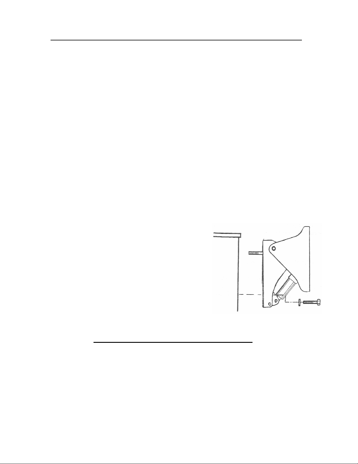
5. To mount the Motor Lift bracket to the transom use four ½ inch diameter stainless steel
bolts with washers and nylon locking nuts. Start by placing a bolt with a washer into each
of the upper mounting holes. Stick a piece of tape over the head of each bolt to hold
them in place, then lift the unit up to the transom, align the bolts and slide the unit into
place. Install the washers and the nuts inside the boat. Do not tighten the nuts com-
pletely until the lower bolts have been installed.
6. Complete the installation by inserting the two lower
mounting bolts, together with washer and the nyl
on locking nuts. Tighten each bolt evenly, taking
care not to over torque the nut to the point where
the transom or the bracket could be damaged.
MOUNTING THE MOTOR
1. Your motor lift bracket is supplied with a plastic 2 X 3 shim to help mount
the motor to the bracket.
2. Place the shim on the inside of the mounting plate and hold it in place while
placing the motor over the top edge of the bracket.


THE BREATHER TUBE
MUST
MUST

ELECTRICAL CONNECTIONS
This unit is designed to operate off of a standard 12 volt battery and is generally connected to
the boats main starting battery. Follow the illustration and instructions below:
1. Mount the electrical control module inside the boat using the two ½ inch screws
provided
2. The push button switch can be mounted in any convenient location near the drivers’
seat. For tiller operated motors, the switch can be strapped to the tiller arm with ca-
ble ties.
3. Run the three pronged switch lead to the control relay module and the two pronged
lead from the control module to the bracket.
4. Apply a small amount of dielectric grease to each of the connectors and plug them
together. (It is also recommended that these connections be wrapped with a water-
proof tape or shrink tube applied
5. After all connections are made, connect the ring terminal leads to the battery. Con-
nect the red lead to the positive (+) terminal and the black lead to the negative (-)
terminal.
6. Test the unit by running it up and down to make sure that there is adequate slack in
the leads. Then using the cable ties supplied, secure all of the wiring to make sure it
does not get pinched during operation.

MOTOR LIFT SUPPORT CORD
The final step is installing the support stretch cord. This cord is designed to keep the motor
snug to the motor bracket and minimize the movement of the motor while it is being trailered
or while running in the rough waters with the motor lift in the raised position. The cord is de-
signed to be left permanently attached to the motor, meaning you can leave it on while the
motor is in the lowered position and running. When the motor is raised, the cord will auto-
matically tighten as illustrated to keep the motor from “bouncing” in its own bracket.
To attach the cord, simply attach the hooks to the lower
holes in the sides of the motor lift bracket


NOTICE
DAMAGE CAUSED BY IMPROPER TRAILERING PROCEDURES OR WATER INTRUSION
THROUGH THE BREATHER TUBE IS NOT COVERED BY THE PRODUCT WARRANTY. IT IS THE
USER’S RESPONSIBILTY TO INSURE THAT THE NECESSARY PROCEDURES ARE FOLLOWED.
MAINTENANCE
Use in Salt Water Area
3. Adding Grease

TROUBLESHOOTING
The following are some procedures to follow before calling in for service or warranty work:
UNIT DOES NOT RUN
1. Check Battery & Connections.
2. Check Electric Motor.
Use a double lead jumper and connect the motor’s two prong plug directly to a battery.
3. If the motor still does not work, disconnect the motor from the actuator (held on by two small
nuts) and plug directly to the battery.
4. If the motor works when it is disconnected from the actuator, the actuator/motor assembly
needs replaced.
5. If the motor does not work when disconnected from the actuator, the motor needs replaced.
6. Check Relay Control & Push Button Switch.
Unplug the three prong connector at the relay control and jumper between the Red and the
Green wires to go down and between the Red and Blue wires to go up. If the unit does not run
the problem is the relay control.
If it does work then the problem is the likely the push button switch.
UNIT RUNS IN ONE DIRECTION ONLY
1. Check Relay Control & Push Button Switch
Unplug the three prong connector at the relay control and jumper between the Red and the
Green wires to go down and between the Red and Blue wires to go up. If the unit does not run
the problem is the Relay Control.
If it does work then the problem is the Push Button Switch.
UNIT RUNS BUT MAKES A GRINDING NOISE AND HAS LOW POWER
1. Gear case low on grease. Add three to four pumps of marine marine grade grease.
UNIT RUNS BUT DOES NOT MOVE
1. Return or replace Actuator.
UNIT RUNS BUT MAKES CLICKING NOISE OR JUMPS
1. Return or replace actuator.
UNIT STARTS AND RUNS ON ITS OWN
1. Replace relay control.
DETERMINE IF WATER IS IN ELECTRIC MOTOR
1. Remove through bolt that is closest to the wires and look for an indication of rust on the bolt.
If so there is water inside of the motor housing.

SERVICE AND WARRANTY
Should your unit ever require service, please do not return the product to your dealer. Please call the number
below for special instructions on shipping and handling. Please call between 9:00 am - 5:00 pm (Pacic Time)
Monday through Friday. If service is required and covered by warranty, it will be repaired or replaced as
described below. If service is required and not covered by warranty, (such as damage caused from improper
trailering or from water intrusion through the breather tube), replacement parts are available for purchase
and may be paid for by Visa or MasterCard.
The warranty coverage on this equipment is limited to the terms set forth below:
CMP Group Ltd. warrants this product to be free of defects in material and workmanship for a period of ONE
(1) YEAR from the date of original retail purchase. Positive proof of date of purchase is required for warranty
service. If service is required and covered by warranty, the unit will be repaired or replaced with new or factory
rebuilt parts at no charge. The defective components must be returned to the address specied, with shipping
charges prepaid. Be sure to include your name, address, telephone number and a copy of the sales receipt
showing the date of original retail purchase. All sales receipts are subject to verication.
This warranty does not apply if the unit has been damaged by accident, abuse, misuse, poor installation or
misapplication, or if it has been modied from its original condition, or if any serial number has been removed
or defaced or altered. This warranty does not cover any expense to remove or reinstall the unit or any of its
components. If a returned unit is not covered by warranty, the sender will be notied and given an estimate
of the charges to repair or replace the unit, together with the return shipping charges.
THIS WARRANTY DOES NOT COVER SPECIAL, INCIDENTAL, OR CONSEQUENTIAL DAMAGES RESULTING FROM
ANY BREACH OF WARRANTY, OR UNDER ANY OTHER LEGAL THEORY, INCLUDING BUT NOT LIMITED TO
DAMAGE TO OR REPLACEMENT OF OTHER EQUIPMENT AND PROPERTY. THE WARRANTY AND REMEDIES SET
FORTH ARE EXCLUSIVE AND IN LIEU OF ALL OTHERS, WHETHER ORAL OR WRITTEN, EXPRESS OR IMPLIED. DUE
TO THE SPECIAL AND UNIQUE CONDITIONS THAT MAY EXIST IN EACH APPLICATION, THE MANUFACTURER
SPECIFICALLY DISCLAIMS ANY AND ALL IMPLIED WARRANTIES OF MERCHANTABILITY AND FITNESS FOR A
PARTICULAR PURPOSE. NO DEALER, AGENT OR EMPLOYEE IS AUTHORIZED TO MAKE ANY MODIFICATION,
EXTENSION OR ADDITION TO THIS WARRANTY.
Some states do not allow exclusion of incidental or consequential damages, so the above exclusions may not
apply to you. This warranty gives you specic legal rights, and you may also have other legal rights, which may
vary from state to state.
1.604.940.2010 | sales@cmpgroup.net
This manual suits for next models
1
Table of contents
Other CMP Boating Equipment manuals
Popular Boating Equipment manuals by other brands

Dynamic Dollies & Racks
Dynamic Dollies & Racks SUNISH Assembly instructions

SLEIPNER MOTOR AS
SLEIPNER MOTOR AS SIDE-POWER SE-50/140 S Installation and user manual

Jula
Jula 650266 Assembly instructions

SeaView
SeaView PM5-FMH-8 installation instructions

Opacmare
Opacmare Box Gangway 1204 Use and maintenance instructions

bamar
bamar MEJ 4.02 Use and maintenance instruction manual