CMT ORANGE TOOLS CMT3 User manual

PIALLETTO ELETTRICO PORTATILE
GB
PORTABLE ELECTRIC PLANER
D
TRAGBARE ELEKTRO-HOBEL
F
RABOT ELECTRIQUE PORTABLE
E
ACEPILLADORA ELECTRICA PORTATIL
NL
ELEKTRISCHE HANDSCHAAFMACHINE
GR
ÖOPHTH HËEKTPH ∆ËANH
P
PLAININHO ELETRICO PORTÁTIL
S
PORTABEL HYVELMASKIN
DK
RANSPORTABEL ELEKTRISK HØVLEMASKINE
N
BÆRBAR ELEKTRISK HØVEL
SF
KANNETTAVA SÄHKÖYLÄKONE
ISTRUZIONI PER L'USO • INSTRUCTIONS FOR USE • BETRIEBSANLEITUNG
INSTRUCTIONS DE SERVICE • INSTRUCCIONES PARA EL USO • GEBRUIKSAANWIJZING
ÏÄÇÃÉÅÓ ∞PÇÓÇÓ
• INSTRUÇÕES DE USO • BRUKSANVISNING
BRUGSANVISNG • BRUKERVEILEDNING • KÄYTTÖOHJEET
010/0
6
cod. 5512596714
0
- CMT3 -

PIALLETTO ELETTRICO PORTATILE
pag.
1
GB
PORTABLE ELECTRIC PLANER
pag.
5
D
TRAGBARE ELEKTRO-HOBEL
seite
9
F
RABOT ELECTRIQUE PORTABLE
page
13
E
ACEPILLADORA ELECTRICA PORTATIL
pag.
17
NL
ELEKTRISCHE HANDSCHAAFMACHINE
pag.
21
GR
ÖOPHTH HËEKTPH ∆ËANH
óåë
.
25
P
PLAININHO ELETRICO PORTÁTIL
pag.
29
S
PORTABEL HYVELMASKIN
side
33
DK
RANSPORTABEL ELEKTRISK HØVLEMASKINE
side
37
N
BÆRBAR ELEKTRISK HØVEL
side
41
SF
KANNETTAVA SÄHKÖYLÄKONE
sid 45

32
54
1
E
G
F
A
B
D
H
C
A
B
C
2
1
B
3
4
A
I
A
1
INDICE
INTRODUZIONE pag. 1
1. INFORMAZIONI GENERALI » 1
2. CARATTERISTICHE TECNICHE » 1
3. NORME GENERALI PER
LA SICUREZZA » 2
4. INSTALLAZIONE » 2
5. REGOLAZIONE » 2
6. FUNZIONAMENTO E USO » 2
7. MANUTENZIONE » 3
8. SOSTITUZIONE PARTI » 3
TABELLA ACCESSORI A RICHIESTA » 49
INTRODUZIONE
Tutti gli utensili portatili
CMT
sono conformi alla Norma
EN
50144
, alla
direttiva macchine 98/37 CE
e successive
modifi che, alle
73/23 CEE
e
93/68 CEE
e, per ciò che
attiene alla compatibilità elettromagnetica, alla direttiva
89/336 CEE
, alle Norme
EN 55014-1
,
EN 55014-2
,
EN
61000-3-2
,
EN 61000-3-3
.
Il Marchio
apposto sull’utensile ne
garantisce la conformità.
garantisce la conformità.
garantisce la conformità.
Se utilizzato con cura e sottoposto a regolare
manutenzione Vi durerà a lungo.
Seguite attentamente le istruzioni contenute in questo
manuale, tenetelo con cura ed a portata di mano per gli
eventuali controlli degli organi preposti.
1 INFORMAZIONI GENERALI
1.0 SCOPO DEL MANUALE
Questo manuale è stato redatto dal costruttore e
costituisce parte integrante del corredo dell’utensile.
Le informazioni contenute sono dirette a operatori
professionisti.
Questo manuale defi nisce lo scopo per cui l’utensile è
stato costruito e contiene tutte le informazioni necessarie
per garantirne un uso sicuro e corretto; si raccomanda
pertanto di consultare attentamente questo manuale
prima di procedere a qualsiasi intervento di regolazione,
uso, manutenzione.
La costante osservanza delle norme in esso contenute
garantisce la sicurezza dell’uomo e della macchina,
l’economia di esercizio ed una più lunga durata di
funzionamento dell’utensile stesso.
Fotografi e e disegni sono forniti a scopo esemplifi cativo;
il costruttore, nel perseguire una politica di costante
sviluppo ed aggiornamento del prodotto, può apportare
modifi che senza alcun preavviso.
1.1 IDENTIFICAZIONE DELL’UTENSILE
La targhetta logo posta sul lato sx dell’utensile identifi ca
il Costruttore, la targhetta dati posta sul corpo motore
dell’utensile contiene i riferimenti del modello ed i dati
tecnici del motore e del suo costruttore.
1.1.1 IDENTIFICAZIONE
(fi g. 1)
A Targhetta logotipo
B Targhetta dati
C Impugnatura
D Interruttore
E Pomello regolazione profondità
F Guida parallela
G Pomello di fi ssaggio
H Pulsante di sblocco interruttore
I Carter copri cinghia
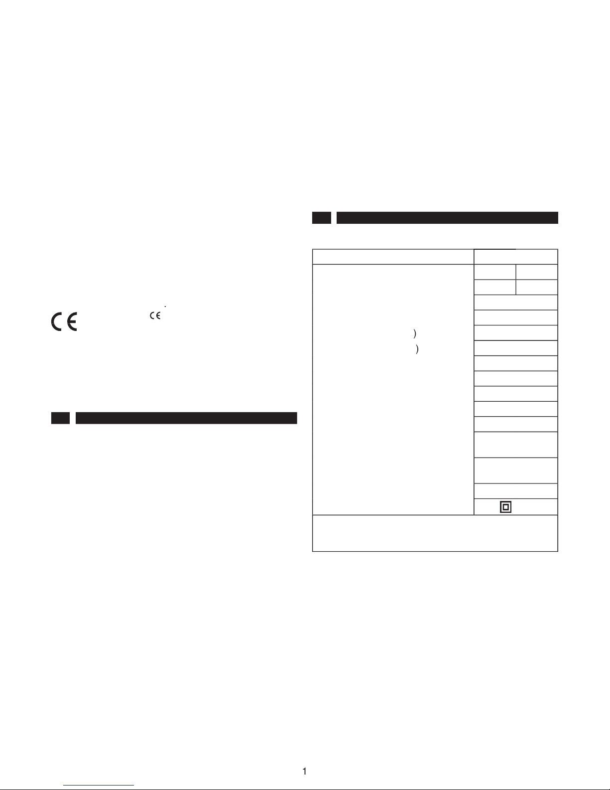
2 CARATTERISTICHE TECNICHE
2.1 DATI TECNICI
M
odello
CMT3
Tensione (V~) (*)
230-240
110
Corrente (A)
3,7
7,9
Frequenza (Hz)
50-60
Potenza assorbita (W)
850
Velocità a vuoto (min
-1
)
13000
Velocità a carico (min
-1
)
9500
Dimensioni piano (mm)
80x286
Profondità di taglio (mm)
0-3
Larghezza di piallatura (mm)
82
Profondità di battuta (mm)
23
Peso (Kg)
2,8
Pressione sonora emessa
Lpa (dB
A
) (**)
90
Potenza sonora emessa
Lwa (dB
A
) (**)
103
Livello di vibrazioni (m/s
2
) (**)
3,2
Classe di isolamento
/
II
* Vedi paragrafo 4.3
** Rilievi eseguiti secondo le norme:
EN 50144-1 - EN 50144-2-14
2.2 DOTAZIONE STANDARD:
Guida parallela ad inclinazione regolabile; appoggio
graduato; chiavi di servizio.
La dotazione di serie può variare a seconda della versione
acquistata e della campagna commerciale in atto.
2.3 ACCESSORI A RICHIESTA:
Lame, bocchettone di aspirazione, aspiratore, kit per
aspiratore, supporto stazionario.
2.4 DISPOSITIVI PER LA SICUREZZA
L’utensile è stato progettato e costruito per permettervi
di operare in tutte le situazioni in assoluta sicurezza, pur
tuttavia
in particolari condizioni di lavoro ricordate
di adoperare adeguati guanti da lavoro ed occhiali
protettivi.
ISTRUZIONI PER L’USO
PER IL PIALLETTO ELETTRICO PORTATILE

2
L’utensile è stato progettato e costruito per ridurre al minimo
le emissioni di rumore (vedi dati tecnici al 2.1), pur tuttavia
in particolari condizioni Il livello sonoro massimo sul
posto di lavoro potrebbe essere superiore a 85 dBA e
quindi dannoso alla salute e all’udito. In questo caso
l’operatore deve proteggersi dal rumore eccessivo
mediante l’utilizzo di una cuffi a.
Siate prudenti nell’affrontare il vostro lavoro e tenete in
ordine il vostro utensile ne và della vostra sicurezza.
2.4.1 INTERRUTTORE
Onde evitare partenze accidentali la macchina è dotata di
un dispositivo di sicurezza, per cui occorre prima premere
il pulsante nero
H
(fi g. 1) a fi anco dell’impugnatura, poi
premere il pulsante di avvio.
2.4.2 CARTER DI PROTEZIONE
Onde proteggere il rullo da contatti accidentali con
l’operatore è stato protetto da un carter fi sso (lato cinghia)
e da un carter mobile che consente all’occorrenza di
sostituire anche la lama. In tal modo il rullo (e quindi anche
le lame) non sono accessibili durante l’uso.
2.4.3 PROFONDITÀ DI TAGLIO
E’ possibile effettuare la regolazione della profondità
di taglio senza dover ribaltare la macchina, agendo
sull’apposito pomello.
2.4.4 GUIDE
Durante l’uso è consigliabile adottare la guida parallela
e l’appoggio graduato, oppure montare il pialletto su
supporto stazionario.
Ciò Vi consentirà un lavoro di maggior qualità e Vi fornirà
una maggior sicurezza.
2.4.5 IMPUGNATURE
Il pialletto è dotato di una impugnatura ergonomica e di un
pomolo, che consente di regolare la profondità di taglio.
Attenzione
Durante l’uso è obbligatorio tenere bene le due mani
sulle impugnature.
3 NORME GENERALI PER LA SICUREZZA
Vedi allegato:
Norme generali per la sicurezza.
E’ un libretto che è parte integrante di questo manuale.
4 INSTALLAZIONE
4.1 IMBALLO
L’utensile acquistato, completo di accessori e manuale per
l’uso, è contenuto in un imballo di cartone di dimensioni
idonee e di spessore idoneo all’uso previsto per questi
utensili, tenetelo con cura vi servirà per il vostro lavoro.
4.2 INSTALLAZIONE
Le condizioni ambientali, la temperatura, l’umidità,
l’illuminazione, la corretta dislocazione del vostro
utensile e la pulizia dell’ambiente di lavoro, sono
condizioni importanti ai fi ni della sicurezza personale e
del rendimento dell’utensile stesso. Teneteli sempre sotto
controllo lavorete meglio ed in maggior sicurezza.
4.3 ALLACCIAMENTO ELETTRICO
Prima di collegare l’utensile alla rete di alimentazione
accertarsi che sia rispondente alle norme vigenti del paese
di utilizzo e che il voltaggio e la frequenza corrispondano
a quanto indicato nella targhetta dati.
Per l’utilizzo di prolunghe accertarsi che la sezione dei
cavi sia adeguata alla lunghezza delle stesse. Qualora si
faccia uso di prolunghe avvolgibili assicurarsi del totale
svolgimento per evitare il verifi carsi di surriscaldamenti.
4.4 POSTO DI LAVORO
L’utensile da voi acquistato è un elettroutensile portatile.
Per il suo impiego è previsto un solo utente, vista la sua
conformazione, il suo peso e la sua manegevolezza.
L’impiego normale prevede le mani dell’operatore poste
saldamente sulle due impugnature.
5 REGOLAZIONE
L’utensile viene consegnato dal costruttore regolato
secondo parametri standard.
All’occorrenza è possibile
effettuare la regolazione della profondità di taglio.
5.1 REGOLAZIONE DELLA PROFONDITÀ DI
TAGLIO
Predeterminate la profondità di piallatura, ruotando la
manopola
E
(fi g. 1) fi no a portare il relativo indice sul
valore prescelto. E’ possibile variare la profondità di taglio
da 0 a 3 mm.
5.2 REGOLAZIONE DELLA PLANARITÀ DI TAGLIO
Se durante l’uso o dopo aver sostituito dei componenti
avete la necessità di regolare la planarità del taglio,
procedete come al punto 8.4 .
6 FUNZIONAMENTO E USO
6.1 SICUREZZA
Il pialletto CMT3 è una macchina di notevole resistenza
e robustezza particolarmente versatile maneggevole per
tutti i lavori continuativi di piallatura su legno.
Guidate il pialletto con entrambe le mani sulle
impugnature.
Tenete il cavo di alimentazione in modo che durante il
lavoro non Vi sia di impedimento e non sia a contatto
con l’utensile.
I pezzi piccoli devono essere fi ssati in modo che durante
la piallatura non possano spostarsi (bloccateli, ad es.,
con un morsetto).
ATTENZIONE:
Aspettare che l’attrezzo si sia fermato completamente
prima di riporlo.
6.2 MESSA IN FUNZIONE
La macchina viene fornita già pronta per l’uso, occorre
solamente predeterminare la profondità di piallatura.
ITALIANO

3
ITALIANO
-Qualora necessiti l’esecuzione di piallatura a distanza
prestabilita da una battuta a 90° o comunque inclinata
rispetto al piano di lavoro, esiste la possibilità di installare
sulla macchina, l’apposita guida laterale
F
in dotazione
come mostra la (fig. 1). Tale guida possiede sia la
regolazione della profondità di battuta (agendo sul pomello
G
) sia la regolazione dell’inclinazione della squadra di
appoggio agendo sui dadi ad alette.
-L’allineamento tra due differenti piani di lavoro ad altezza
diversa, (fi g. 4) si effettua ponendo l’appoggio graduato
4
all’altezza voluta, agendo sul pomolo
3
di fi ssaggio.
6.3 DIREZIONE DI AVANZAMENTO
La direzione di avanzamento del pialletto deve sempre
essere come in fi g.5.
La direzione di rotazione del rullo è indicata da una freccia
sul carter lato cinghia.
6.4 LAME
La macchina è dotata di coltelli HWM ‘usa e getta’,
utilizzabili da entrambe le parti. Per un rendimento ottimale
e continuo, controllare periodicamente lo stato dei coltelli,
e se necessario procedere alla loro sostituzione.
Usate sempre e soltanto lame perfettamente affi late.
Usare esclusivamente lame e portalame CMT.
6.5 ASPIRAZIONE DEI TRUCIOLI
E possibile convogliare i trucioli di lavorazione al fi ne di un
impiego più pulito del posto di lavoro. Utilizzare sempre
lo schermo protettivo.
6.6 USO DEL PIALLETTO CON SUPPORTO
STAZIONARIO
(fi g. 5)
Il supporto stazionario trasforma il pialletto portatile in
fi sso.
Utilizzare sempre lo schermo protettivo.
Per lavorare piccoli pezzi di legno, utilizzare l’apposito
spingitore.
Prima di montare il pialletto sul supporto accertarsi che
la spina sia disinserita dalla rete.
6.7 USO IMPROPRIO
Le funzioni e l’uso dell’utensile da lei acquistato sono solo
ed esclusivamente quelle indicate in questo manuale.
Non adoperate su materiali diversi dal legno.
E’ esplicitamente vietato ogni altro uso dell’utensile.
7 MANUTENZIONE
Un’ispezione regolare ridurrà la necessità di manutenzione
e terrà il Vostro utensile in buone condizioni di lavoro, I
cuscinetti sono lubrifi cati per la vita dell’utensile. Il motore
deve essere correttamente ventilato durante l’impiego
dell’utensile. Per questo evitare di appoggiare le mani sulle
bocche di ventilazione. Dopo ogni utilizzazione, distaccare
l’utensile dalla corrente e pulirlo accuratamente.
7.1 SMALTIMENTO
Alla fi ne della vita della macchina, o quando essa non
è più riparabile, assicurarsi che lo smaltimento della
stessa sia effettuato secondo le norme vigenti nel paese
di utilizzo, e sempre da personale specializzato ed allo
scopo autorizzato.
In ogni caso:
- Non disperdere nell’ambiente;
- Non accomunare con i rifi uti solidi urbani;
- Rivolgersi agli appositi centri di riciclaggio.
8 SOSTITUZIONE PARTI
ATTENZIONE - Prima di effettuare qualsiasi operazione
di sostituzione di parti disinserire la spina dalla presa
di corrente.
8.1 SPAZZOLE
Le spazzole vanno sostituite dopo circa 150÷200 ore di
lavoro o se la loro lunghezza è inferiore a 5÷6 mm.
ATTENZIONE - Per un corretto funzionamento
dell’utensile sostituire sempre le spazzole a coppie e
non singolarmente. Si raccomanda l’uso di ricambi
originali CMT.
Svitare le viti
1
, togliere il carter
2
, pulire il portaspazzole
con un getto di aria asciutta (fi g. 4).
Sulle spazzole appoggia l’estremità di una molla a
spirale, sollevando queste molle si possono estrarre le
spazzole.
Con una pinzetta staccare i connettori dal portaspazzole,
alzare la molla a spirale e tenerla sollevata, estrarre la
spazzola tirandola per la propria treccia, sempre tenendo
alzata la molla a spirale, introdurre la nuova spazzola
facendo attenzione che sia inserita nel verso giusto e che
la treccia scorra nella propria asola.
Appoggiare di nuovo la molla in testa alla spazzola e quindi
collegare i connettori al portaspazzole.
Rimontare il carter e serrare bene le 3 viti.
Attenzione
Occorre effettuare questa operazione presso un centro
di assistenza autorizzato.
ATTENZIONE - Dopo il montaggio delle nuove spazzole
fare funzionare il motore per almeno 5 minuti a vuoto.
8.2 SOSTITUZIONE DEL CAVO DI
ALIMENTAZIONE
Controllare che le condizioni del cavo di alimentazione
siano buone ed in caso contrario
farlo sostituire presso
un centro di assistenza autorizzato.
8.3 SOSTITUZIONE DEI COLTELLI IN METALLO
DURO
Capovolgere il pialletto e appoggiarlo dalla parte della
cinghia, far girare il rullo
A
con le mani affi nché sia visibile
la lama
C
(fi g. 2).

4
ITALIANO
Avvitare le tre viti di fi ssaggio
B
fi no a liberare la lama
C
(fi g. 2).
Sfi lare la lama
C
lateralmente, (vedi freccia fi g. 2) tenendo
sollevata la protezione di plastica
B
(fi g. 4) e tenendo nella
sua sede il portalama.
Sostituire o girare la lama inserendola con il piano rivolto
verso la testa dei bulloni di fi ssaggio (fi g. 3).
ATTENZIONE - Per un corretto funzionamento della
macchina è molto importante che la lama sia inserita
nel verso giusto come in fi g. 6.
Svitare le viti di fi ssaggio
B
(fi g. 2) fi no a fi ssare saldamente
la lama ed il portalama al rullo
A
.
Ripetere l’operazione per l’altra lama.
ATTENZIONE
Dopo aver compiuto questa operazione, assicurarsi che
lama e portalama siano ben fi ssi al rullo, in caso contrario
potrebbero verifi carsi gravi incidenti.
8.4 SOSTITUZIONE DEL PORTALAME
(fi g.2)
Effettuare una accurata pulizia delle lame e dei
portalame.
Ripetere le operazioni effettuate per la sostituzione della
lama e contemporaneamente alla lama sfi lare anche il
portalama e procedere alla sostituzione (fi g. 2).
ATTENZIONE
- Prima di inserire il portalama nel rullo,
assicurarsi che i grani
A
posti sul portalama (fi g. 3)
siano avvitati a tal punto da non sporgere dal piano del
portalama onde evitare che la lama non sia parallela al
piano di lavoro.
Per verifi care il parallelismo della lama, appoggiare una
riga sul piano di lavoro mobile (fi g. 2) e regolare il piano
con il pomolo
A
(fi g. 4) affi nché la riga sfi ori la lama (fi g.
2).
Nel caso la lama non sia perfettamente in piano è possibile
registrarla avvitando i grani
A
(fi g. 3) rendendo così la lama
parallela al piano di lavoro.
Per un ulteriore conferma effettuare una passata di prova
su un piano in legno e verifi carne il parallelismo.
8.5 SOSTITUZIONE DELLA CINGHIA
L’eventuale sostituzione della cinghia si esegue svitando
le viti di fi ssaggio e togliendo il carter
I
(fi g. 4).
Per questa operazione evitare l’uso di cacciaviti o leve
taglienti per non danneggiare la nuova cinghia.
Attenzione
Occorre effettuare questa operazione presso un centro
di assistenza autorizzato.

5
ENGLISH
INDEX
INTRODUCTION page 5
1. GENERAL INFORMATION » 5
2. TECHNICAL SPECIFICATIONS » 5
3. GENERAL SAFETY STANDARDS » 6
4. INSTALLATION » 6
5. REGULATION » 6
6. OPERATION AND USE » 6
7. MAINTENANCE » 7
8. PART REPLACEMENT » 7
TABLE OF ACCESSORIES
AVAILABLE ON REQUEST
» 49
INTRODUCTION
All
CMT
portable tools conform with standard
EN
50144, CE 98/37 machine directives
and following
modifi cations, with
EEC 73/23, EEC 93/68
and, with regard
to electromagnetic compatibility, the tools conform with
directive
EEC 89/336, and with standards EN 55014-1,
EN 55014-2, EN 61000-3-2, EN 61000-3-3
.
The
mark on the tool guarantees its
conformity.
conformity.
conformity.
If used with the care and serviced regularly, this tool will
provide long-lasting and reliable service.
Carefully follow the instructions contained in this manual,
using them for reference for any eventual controls that may
need to be carried out.
1 GENERAL INFORMATION
1.0 THE AIM OF THIS MANUAL
This manual has been compiled by the manufacturer and
is an integrative part of the tool equipment.
The information contained is for the benefi t of professional
operators.
This manual defi nes the aims for which the tool has been
constructed and contains all the necessary information to
guarantee correct and safe use.
It is therefore strongly recommended that this manual
is consulted before performing any kind of adjustment
operation, use or maintenance tasks.
Constant observance of the standard regulations
contained in this manual will guarantee both machine and
operator safety, economic working and longer functional
operation of the tool itself.
Photographs and drawings have been supplied by the
constructor for exemplifying purposes.
With the aim of following a policy of constant development
and product modernization, the constructor is entitled to
make modifi cations without forewarning.
1.1 TOOL IDENTIFICATION
The plate located on the left hand side of the tool identifi es
the model, the data plate located on the right hand side
of the tool contains the model references, the technical
specifi cations of the motor and the constructor.
1.1.1 IDENTIFICATION
(fi g.1)
A Logotype plate
B Data plate
C Handgrip
D Switch
E Depth regulation knob
F Parallel guide
G Clamping knob
H Switch unlocking push-button
I Guard
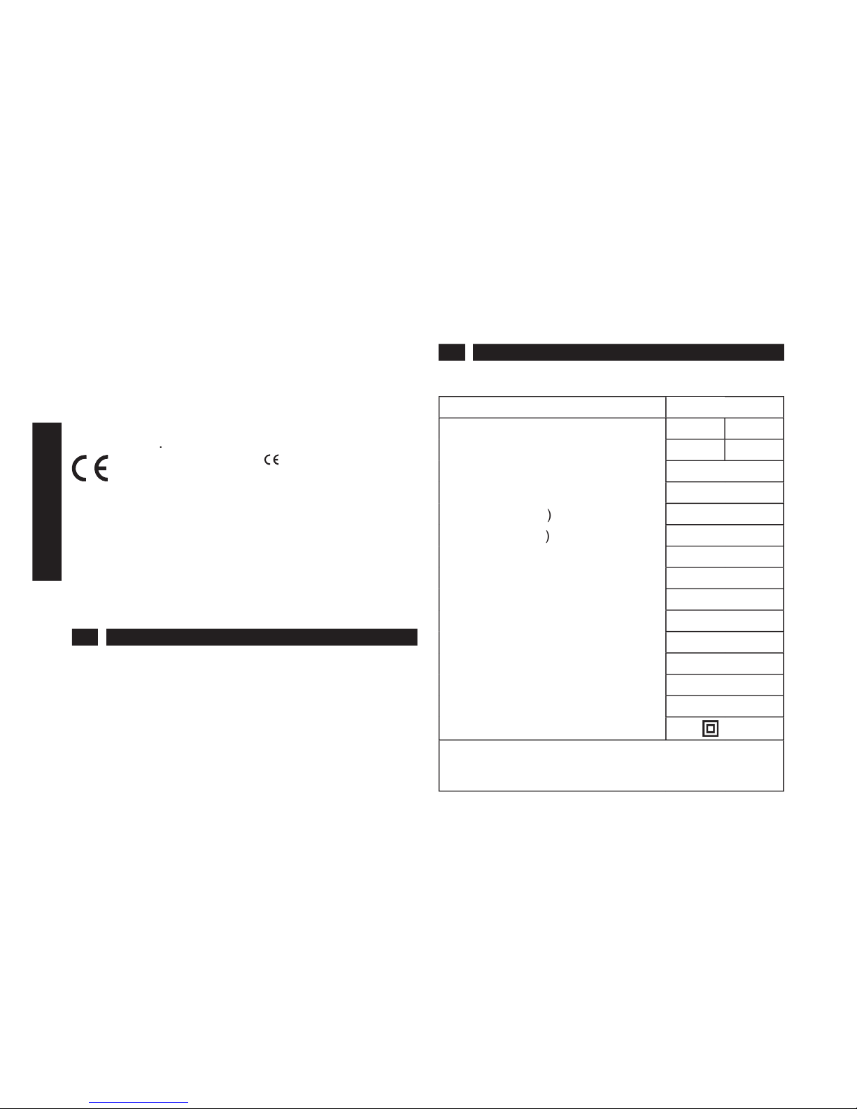
2 TECHNICAL SPECIFICATIONS
2.1 TECHNICAL DATA
M
ODEL
CMT3
Voltage (V~) (*)
230-240
110
Current (A)
3,7
7,9
Frequency (Hz)
50-60
Absorbed power (W)
850
R.p.m. (unloaded) (min
-1
)
13000
R.p.m. fully-loaded (min
-1
)
9500
Plane dimensions (mm)
80x286
Cutting depth (mm)
0-3
Width of plane (mm)
82
Depth of rabbet (mm)
23
Weight (Kg)
2,8
Sound pressure emitted
Lpa (dB
A
) (**)
90
Sound power emited
Lwa (dB
A
) (**)
103
Vibration level (m/s
2
) (**)
3,2
Insulation class
/
II
* See paragraph 4.3
** Surveys carried out according to standards:
EN 50144.1 - EN 50144.2.14
2.2 STANDARD EQUIPMENT:
Parallel adjustable inclined guide, graduated support,
service spanner.
The series fi ttings may vary according to the model
purchased and the actual commercial situation.
2.3 ACCESSORIES AVAILABLE ON REQUEST:
Blades, Suction union, Suction unit, kit for suction unit,
stationary support.
2.4 SAFETY STANDARDS
The tool has been designed and constructed to permit
operation in all situations and in absolute safety.
In particular working conditions remember to use
protective gloves and safety goggles.
INSTRUCTION MANUAL FOR
PORTABLE ELECTRIC PLANER

6
ENGLISH
The tool has been designed and constructed to reduce
noise to minimum levels. (See technical data 2.1).
In particular working conditions the maximum sound
level at the place of work may exceed 85 dBA. In this
case the operator must use ear protectors.
Work carefully and maintain the tool in perfect working
order, for your own safety.
2.4.1 SWITCH
In order to prevent accidental starting the machine is
equipped with a safety device. Therefore the black button
H
(fi g.1), positioned beside the handgrip, must be pressed
fi rst and then the start button.
2.4.2 GUARD
In order to protect the roller from accidental contact with
the operator, it has been protected with a fi xed safety
guard (on the belt side) and a movable guard, that will
allow blade changing operations to be performed, if
necessary. In this manner access cannot be gained to
the roller (or the blades) during use.
2.4.3 CUTTING DEPTH
The cutting depth can be regulated without having to
overturn the machine, by means of the special knob.
2.4.4 GUIDES
During working operations it is advised to use the parallel
guide and graduated support, or to fi t the planer on the
stationary support.
This will produce better quality work and guarantee major
safety for the user.
2.4.5 HANDGRIPS
The planer is equipped with an ergonomic handgrip and a
knob, which allows the cutting depth to be regulated.
Attention
Both of the operator’s hands must be fi rmly kept on the
handgrips during working operations.
3 GENERAL SAFETY STANDARD
See attached information:
General safety standards
.
This booklet forms an integrative part of this manual.
4 INSTALLATION
4.1 PACKAGING
This tool is sold complete with accessories and the
user’s manual, contained in a cardboard box of suitable
size and thickness for the work that the tool is intended
for. This container should be kept as it will prove useful
for your work.
4.2 INSTALLATION
The environmental conditions, temperature, humidity,
lighting, the correct dislocation of your tool and the
cleanliness of the place of work are important conditions
for personal safety and tool performance. These factors
should always be kept under control in order to improve
working conditions and ensure safety.
4.3 ELECTRICAL CONNECTION
Before connecting the tool to the mains make sure that it
complies with the standard regulations of the country in
question, and that the voltage and frequency correspond
to the details on the data plate.
When using extension leads, make sure that cable cross-
section conforms to the length of the lead. When using a
wind-up extension make sure that is completely unwound
so as to avoid overheating.
4.4 PLACE OF WORK
The tool that you have purchased is a portable electric
power tool.
Only one user should operate this tool, given its shape,
weight and maneuverability.
Normal use requires that both of the operator’s hands are
fi rmly kept on the two handgrips.
5 REGULATION
The tool is already regulated according to standard
parameters by the constructor when supplied.
If necessary the cutting depth can be adjusted.
5.1 CUTTING DEPTH REGULATION
Once the planing depth has been determined, rotate the
rotating knob
E
(fi g.1) until the selected value is indicated.
The cutting depth can be regulated from 0 to 3 mm.
5.2 REGULATION OF THE CUTTING FLATNESS
If during use, or after having replaced components,
the cutting fl atness needs to be regulated, proceed as
described in point 8.4.
6 OPERATION AND USE
6.1 SAFETY
The CMT3 planer is a particularly sturdy and resistant
machine; extremely versatile and maneuverable, ideal for
all continuous wood planing work.
Guide the planer with both hands firmly on the
handgrips.
During use, make sure that the power supply cable does
not impede working operations or come into contact with
the tool.
Small work pieces should be securely clamped in order
that they remain in position during planing operations (for
example: fi x in position with a clamp).
ATTENTION:
Wait until the tool has completely stopped before putting
it down.
6.2 STARTING THE MACHINE
The machine is supplied ready for use, requiring only the
planing depth to be determined:
- If planing operations need to be carried out at a preset

7
ENGLISH
distance from a 90° rabbet, or one which is to some extent
slanted in relation to the work surface, the special side
guide
F
(supplied with the machine) can be fi tted (see
fi g.1). This guide can both adjust the depth of the rabbet
(by means of knob
G
) and can regulate the slanting angle
of the support square (using the wing nuts).
- Alignment of two different work surfaces at two different
heights (fi g.4), can be performed by setting the graduated
support
4
to the desired height and by manipulating the
clamping knob
3
.
6.3 DIRECTION OF ADVANCEMENT
The planer advancement direction should always be as
shown in fi g.5.
The roller rotation direction is indicated by an arrow on
the safety guard (belt side).
6.4 BLADES
The machine is equipped with disposable HWM double-
sided blades. For optimal long term performance,
periodically check the condition of the blades and, if
necessary replace them.
Only use perfectly sharpened blades!
Only use CMT blades and blade holders.
6.5 SHAVINGS SUCTION UNITS
Shavings can be removed by means of suction units,
in order to keep working areas clean.
Always use the
protective screen.
6.6 USE OF PLANER WITH STATIONARY
SUPPORT
(fi g.5)
The stationary support transforms the portable planer
into a stationary unit.
Always use the protective screen.
To work small pieces of wood, use the pusher for that
purpose.
Before mounting the planer on the support make sure that
it has been unplugged from power supply.
6.7 IMPROPER USE
The functions and use of this tool are those exclusively
indicated in this manual.
ANY OTHER USE OF THE TOOL IS EXPLICITLY
FORBIDDEN !
7 MAINTENANCE
Regular inspection reduces the necessity for maintenance
operations and will keep your tool in good working
condition. The tool bearings are life-long lubricated. The
motor must be correctly ventilated during tool operation.
For this reason avoid blocking the air inlets with hands.
After use, disconnect the tool from the power supply and
clean carefully.
7.1 DISPOSAL
At the end of the machine’s working life, or when it can
no longer be repaired, ensure that it is disposed of
according to the standard regulations of the country in
which it is being used, and that the disposal operation is
carried out by specialized personnel following authorized
guidelines.
In all circumstances:
- Do not abandon in the environment;
- Do not dispose of together with solid urban waste
products;
- Contact the special recycling centers.
8 PARTS REPLACEMENT
Attention!
Disconnect the plug from the power supply socket before
replacing any parts.
8.1 BRUSHES
The brushes must be replaced after approx. 150-200
working hours, or if they are less then 5-6 mm in length.
Attention!
For correct tool operation always change the brushes
in pairs, not separately. The use of original CMT spare
parts is recommended.
In order to carry out replacement operations, proceed
as follows:
Unscrew the screws 1, remove the guard 2 and clean the
brush holder using a jet of dry compressed air (fi g.4).
The edge of a spiral spring rests on the brushes, by raising
this spring the brushes can be extracted.
Remove the connectors from the brush holder using a
pair of pincers, raise the spiral spring, maintaining it in the
raised position. Extract the brush, holding it by the braided
connector and, with the spring raised, insert the new
brush, taking care that it is inserted in the correct direction
and that the braided connector slides into the slot.
Replace the spring on the brush head and then connect
the connectors to the brush holder.
Replace the guard and fully tighten the three screws.
Attention!
This operation should only be performed by an authorized
service center.
ATTENTION: After fi tting new brushes allow the motor
to run idle for 5 minutes.
8.2 REPLACING THE POWER SUPPLY CABLE
Check that the power supply cable is in good condition, if
not have it replaced by an authorized service center.
8.3 REPLACEMENT OF THE HARD METAL
BLADE
Overturn the planer and rest it on the belt side, manually
rotate roller
A
until the blade is visible
C
(Fig.2).
Tighten the three retaining screws
B
until the blade
C
is
liberated (Fig.2).
Slide out the blade
C
from the side (see the arrow in Fig.2),
keeping the plastic protective guard
B
raised (Fig.4) and
the blade support in position.

8
ENGLISH
Replace or turn the blade over, inserting it with the fl at
surface facing the retaining bolt head (Fig.3).
Attention - For correct machine operation it is essential
that the blade is inserted in the right direction, as shown
in Fig. 6.
Loosen the retaining screws
B
(Fig.2). until the blade and
blade support are securely fastened to roller
A
.
Repeat the operation for the other blade.
Attention - After having completed this operation, ensure
that the blade and blade support are securely fastened to
the roller, if not serious accidents may occur.
8.4 REPLACEMENT OF THE BLADE SUPPORT
(Fig.2)
Carefully clean the blade and the blade support.
Repeat the operations performed for blade replacement,
but when sliding out the blade also remove the blade
support. Then proceed to replacement operations
(Fig.2).
Attention
- Before inserting the blade support on the roller,
make sure that grub screws
A
, fi tted on the blade support
(Fig.3), are tightened so that they do not protrude from the
blade support surface; this is to avoid that the blade is not
positioned parallel to the working surface.
In order to check the parallel position of the blade, place a
ruler on the mobile working surface (Fig.2) and adjust the
surface, using knob
A
(Fig.4), until the blade just touches
the ruler (Fig.2).
If the blade is not perfectly level, it can be adjusted by
tightening grub screws
A
(Fig.3), thereby rendering the
blade perfectly parallel to the work surface.
For ulterior verifi cation, pass the blade over a wooden
surface and check the parallel position.
8.5 REPLACEMENT OF THE BELT
The eventual replacement of the belt can be carried
out by loosening the retaining screws and removing the
guard
I
(Fig.1).
Avoid using screwdrivers or sharp levers for this operation,
as they may damage the new belt.
Attention!
This operation should only be performed by an
authorized service center.
9
DEUTSCH
INHALT
EINLEITUNG seite 9
1.
ALLGEMEINE HINWEISE » 9
2. TECHNISCHE EIGENSCHAFTEN » 9
3. ALLGEMEINE
SICHERHEITSVORSCHRIFTEN » 10
4. INSTALLATION » 10
5. EINSTELLUNG » 10
6. FUNKTION UND GEBRAUCH » 10
7. WARTUNG » 11
8. ERSATZTEILE » 11
LISTE DES ZUBEHÖRS AUF WUNSCH
» 49
EINLEITUNG
Alle tragbaren Werkzeuge von
CMT
entsprechen der
EN-Norm 50144
, der
CE-Maschinenrichtlinie 98/37
und anschließenden Änderungen,
73/23 EWG
und
93/68
EWG
und, was die Vorschriften zur elektromagnetischen
Verträglichkeit betrifft, der EG-Richtlinie
89/336,
den
Normen
EN 55014-1, EN 55014-2, EN 61000-3-2
und
EN 61000-3-3
.
Das Warenzeichen
auf dem Werkzeug
garantiert diese Konformität.
garantiert diese Konformität.
garantiert diese Konformität.
Eine umsichtige Verwendung und regelmäßige Wartung
gewährleisten Ihnen eine lange Funktionstüchtigkeit des
Werkzeuges.
Folgen Sie aufmerksam den vorliegenden
Bedienungsanleitungen, bewahren Sie dieses Heft
sorgfältig und in greifbarer Nähe auf. Es wird Ihnen bei der
Kontrolle der der Maschinenteile behilfl ich sein.
1 ALLGEMEINE HINWEISE
1.0 ZWECK DIESES HANDBUCHES
Das vorliegende Handbuch wurde vom Hersteller erstellt
und ist Bestandteil des Lieferumfangs der Maschine.
Die darin enthaltenen Hinweise sind an den
fachmännischen Arbeiter gerichtet.
Das Handbuch defi niert den Einsatzbereich der Maschine
und enthält alle, für einen sicheren und korrekten Betrieb
erforderlichen Hinweise; diese Anleitungen sind daher vor
jeglichem Eingriff für Einstellung, Gebrauch oder Wartung
sorgfältig durchzulesen.
Das generelle Einhalten der vorliegenden Hinweise
garantieren die Sicherheit für Personen und Maschine, die
Wirtschaftlichkeit beim Einsatz und eine lange Haltbarkeit
der Maschine selbst.
Abbildungen und Zeichnungen dienen als Beispiele;
Der Hersteller behält sich im Rahmen seiner konstanten
Entwicklung und Erneuerung des Produkts, jederzeit
das Recht vor, ohne Voranmeldung Änderungen
anzubringen.
1.1 IDENTIFIKATION DER MASCHINE
Das Schild mit dem Logo auf der linken Seite der Maschine
gibt das Modell an, das Typenschild auf der rechten Seite
gibt die Bezugsdaten der Maschine und die technischen
Daten von Motor und Hersteller an.
1.1.1 IDENTIFIKATION
(Abb. 1)
A Logotype
B Datenschild
C Handgriff
D Betriebsschalter
E Tiefeneinstellungsgriff
F Parallelführung
G Befestigungsgriff
H Druckknopf zur Freigabe des Betriebsschalters
I Schutzgehäuse
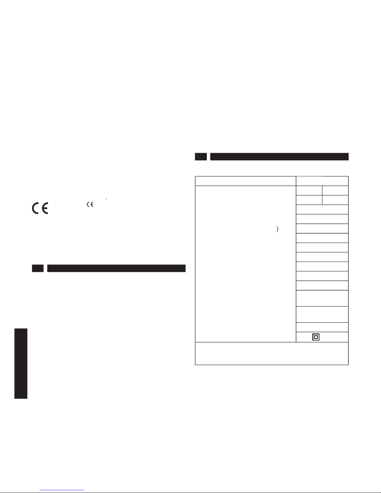
2 TECHNISCHE EIGENSCHAFTEN
2.1 TECHNISCHE DATEN
MODELL
CMT3
Spannung (V~) (*)
230-240
110
Strom (A)
3,7
7,9
Frequenz (Hz)
50-60
Leistungsaufnahme (W)
850
Leerlauf (U/Min
-1
)
13000
Lastlauf (U/Min
-1
)
9500
Abmessungen Arbeitsfl äche (mm)
80x286
Spantiefe (mm)
0-3
Hobelbreite (mm)
82
Anschlagstiefe (mm)
23
Gewicht (kg)
2,8
Geräuschdruck Lpa (dB
A
) (**)
90
Geräuschpegel Lwa (dB
A
) (**)
103
Schwingungspegel (m/s
2
) (**)
3,2
Isolationsklasse
/
II
* Siehe Punkt 4.3
** Messungen nach den Normen:
EN 50144.1 - EN 50144.2.14
2.2 LIEFERUMFANG:
Parallelführung mit regulierbarem Winkelanschlag,
Skalenaufl age, Betriebsschlüssel.
Der serienmäßige Lieferumfang kann je nach Modell und
momentaner Verkaufspromotion variieren.
2.3 ZUBEHÖR AUF WUNSCH:
Hobelmesser, Saugstutzen, Absauger, Satz für Absauger,
Standhalterung.
2.4 SICHERHEITSEINRICHTUNGEN
Die Maschine ist mit besonderem Augenmerk für die
maximale Sicherheit in allen Arbeitssituationen erdacht und
gebaut.
Die Verwendung von Arbeitshandschuhen und
Schutzbrillen ist jedoch in jedem Fall erforderlich.
BETRIEBSANLEITUNG FÜR
TRAGBARE ELEKTRO-HOBEL

10
DEUTSCH
Die Geräuschentwicklung wurde minimal gehalten
(siehe Tabelle techn. Daten 2.1), die jedoch
unter
bestimmten Arbeitsbedingungen 85 dBA übersteigen
kann. In diesem Fall muß sich der Bediener durch
einen Ohrenschutz vor zu großer Lärmbelastung
schützen.
Wir empfehlen im Interesse Ihrer Sicherheit, umsichtig zu
arbeiten und das Gerät sorgfältig aufzubewahren.
2.4.1 BETRIEBSSCHALTER
Die Maschine ist mit einer Sicherheitsvorrichtung
ausgestattet, um ein unbeabsichtigtes Einschalten zu
verhindern. Zuerst die schwarzes Taste
H
(Abb. 1) neben
dem Handgriff und danach die Einschalttaste drücken.
2.4.2 SCHUTZGEHÄUSE
Um die Walze vor unbeabsichtigten Kontaktnahmen
mit dem Bediener zu schützen, wurde sie mit einem
feststehenden Gehäuse (Riemenseite) und einem
abnehmbaren Gehäuse, das im Bedarfsfall auch den
Austausch des Messers ermöglicht, abgedeckt. Dadurch
ist die Walze (und damit auch die Messer) während des
Gebrauchs nicht zugänglich.
2.4.3 SPANTIEFE
Die Spantiefe kann ohne Umkippen der Maschine über
Betätigung des dafür vorgesehenen Griffs eingestellt
werden.
2.4.4 FÜHRUNGSLEISTEN
Während des Gebrauchs sollte die Parallelführung und die
Skalenaufl age verwendet werden, oder der Hobel sollte
auf eine Standhalterung montiert werden.
Dies liefert Ihnen eine hochwertigere Arbeit und gibt Ihnen
größere Sicherheit.
2.4.5 HANDGRIFFE
Der Hobel besitzt einen ergonomischen Handgriff und
einen Knauf, über den die Spantiefe eingestellt werden
kann.
Achtung
Während des Gebrauchs müssen die Handgriffe mit
beiden Händen umfaßt werden.
3 ALLGEMEINE SICHERHEITSVORSCHRIFTEN
Siehe Anlage:
Allgemeine Sicherheitsvorschriften
.
Dieses Handbuch ist Bestandteil der
Bedienungsanleitungen.
4 INSTALLATION
4.1 VERPACKUNG
Das erworbene Gerät, komplett mit Zubehör und
Bedienungsanleitung wird im Karton von geeigneten
Abmessungen und Dicke geliefert, der zur Aufbewahrung
vorgesehen ist.
4.2 INSTALLATION
Umweltbedingungen, Temperatur, Feuchtigkeit,
Beleuchtung, sowie die korrekte Arbeitsposition Ihres
Werkzeugs und die Reinhaltung des Arbeitsplatzes sind
wichtige Faktoren für die persönliche Sicherheit und
die Leistungsfähigkeit der Maschine. Wenn Sie diese
Bedingungen berücksichtigen, erleichtern sie sich die
Arbeit und haben größere Sicherheit.
4.3 ANSCHLUß AN DAS STROMNETZ
Vor Anschluß der Maschine an das Stromnetz, stets
überprüfen, ob dieses den im jeweiligen Land geltenden
Vorschriften entspricht, und ob Spannung und Frequenz
mit den Angaben auf dem Typenschild übereinstimmen.
Bei Verwendung von Verlängerungen überprüfen, ob
der Kabelquerschnitt für die Länge des Kabels geeignet
ist. Werden aufwickelbare Verlängerungen verwendet,
darauf achten, daß sie vollständig abgerollt werden, um
Überhitzungen zu vermeiden.
4.4 ARBEITSPLATZ
Das von Ihnen erworbene Gerät ist ein tragbares
Elektrowerkzeug.
Für seine Anwendung ist aufgrund seiner Bauweise,
seines Gewichts und seiner Handlichkeit nur ein Bediener
vorgesehen.
Bei normaler Anwendung hält der Bediener die Maschine
mit beiden Händen an den Handgriffen fest.
5 EINSTELLUNG
Das Werkzeug wird vor Auslieferung fabriksmäßig nach
Standardkenngrößen voreingestellt.
Bei Bedarf kann die Spantiefe nachreguliert werden.
5.1 EINSTELLUNG DER SPANTIEFE
Die Voreinstellung der Hobeltiefe erfolgt durch Drehen
von Handrad E (Abb. 1), bis der betreffende Zeiger den
gewählten Wert erreicht hat. Die Spantiefe kann von 0 bis
3 mm variiert werden.
5.2 EINSTELLUNG DER SPANEBENHEIT
Sollte während des Gebrauchs oder nach Austausch von
Bestandteilen die Spanebenheit reguliert werden müssen,
ist wie unter Punkt 8.4 vorzugehen.
6 FUNKTION UND GEBRAUCH
6.1 SICHERHEIT
Der Hobel CMT3 ist eine äußerst widerstandsfähige,
robuste und besonders vielseitige Maschine, die für alle
Dauerhobelarbeiten auf Holz zur Anwendung kommt.
Den Hobel mit beiden Händen auf den Griffen führen.
Das Stromkabel ist so zu halten, daß es während der
Arbeit nicht behindert und nicht mit dem Werkzeug in
Berührung kommt.
Kleine Werkstücke müssen befestigt werden, damit sie
sich während des Hobelns nicht verschieben können (z.B.
mit einer Spannbacke feststellen).

11
DEUTSCH
ACHTUNG:
Das Werkzeug erst dann ablegen, wenn es vollständig
stillsteht.
6.2 INBETRIEBNAHME
Das Gerät wird betriebsfertig geliefert. Nur die Spantiefe
muß eingestellt werden.
- Muß die Hobelarbeit mit einem Anschlagsabstand von
90° oder in einem Neigungswinkel zur Arbeitsfläche
ausgeführt werden, kann die mitgelieferte Seitenführung
F
, wie auf Abb. 1 gezeigt, auf der Maschine installiert
werden. Über diese Führungsleiste kann sowohl die
Anschlagsspantiefe (über Griff
G
) als auch die Neigung
des Aufl agewinkels (über die Flügelmuttern) eingestellt
werden.
- Das Fluchten von zwei unterschiedlich hohen
Arbeitsfl ächen (Abb. 4) erfolgt über Befestigungsgriff
3
,
mit dem die Skalenaufl age
4
auf die gewünschte Höhe
eingestellt wird.
6.3 VORSCHUBRICHTUNG
Die Vorschubrichtung des Hobels muß immer mit der in
Abb. 5 gezeigten übereinstimmen.
Die Laufrichtung der Walze wird von einem Pfeil auf dem
Gehäuse an der Riemenseite angegeben.
6.4 MESSER
Die Maschine ist mit ‘Wegwerf’-Messern HWM
ausgestattet, die beidseitig verwendbar sind. Für eine
optimale und kontinuierliche Leistung den Zustand der
Messer regelmäßig kontrollieren und sie, falls nötig,
austauschen.
Immer nur völlig scharfe Messer verwenden.
Ausschließlich Messer und Messerhalterungen von CMT
verwenden.
6.5 SPANABSAUGUNG
Für eine saubere Anwendung am Arbeitsplatz können
die bei der Bearbeitung anfallenden Späne abgesaugt
werden. Stets einen Schutzschirm verwenden.
6.6 ANWENDUNG DES HOBELS MIT
STANDHALTERUNG
(Abb. 5)
Durch die Standhalterung wird der tragbare Hobel zum
feststehenden Gerät.
Stets einen Schutzschirm verwenden.
Für die Bearbeitung kleiner Holzstücke die Stossvorrichtung
verwenden.
Vor der Montage des Hobels auf die Halterung sicherstellen,
daß der Netzstecker gezogen wurde.
6.7 UNSACHGEMÄSSER EINSATZ
Das von Ihnen erworbene Gerät darf ausschließlich zu
den in der vorliegenden Betriebsanleitung angeführten
Funktionen eingesetzt werden.
Jeder andere Einsatz der Maschine ist verboten.
7 WARTUNG
Eine regelmäßige Kontrolle erspart Wartungseingriffe
und hält Ihr Gerät in gutem Betriebszustand. Der Motor
muß während des Einsatzes stets gut belüftet sein.
Niemals die Hände auf das Belüftungsgitter legen. Nach
jedem Gebrauch den Netzstecker ziehen und das Gerät
sorgfältig reinigen.
7.1 ENTSORGUNG
Nach Ablauf der Betriebstüchtigket der Maschine oder
wenn diese nicht mehr zu reparieren ist, muß das Gerät
von dem dafür verantwortlichen Fachpersonal entsorgt
werden.
Auf keinen Fall darf das Gerät:
- verworfen werden;
- zu den festen Abfällen der städtischen Müllentsorgung
beigegeben werden.
- Wenden Sie sich gegebenenfalls an die entsprechenden
Entsorgungsstellen.
8 ERSATZTEILE
ACHTUNG - Vor jedem Eingriff zum Ersatzteilwechsel
Netzstecker ziehen.
8.1 BÜRSTEN
Die Bürsten werden nach etwa 150-200 Betriebsstunden
gewechselt oder wenn sie eine Länge von unter 5-6 mm
erreicht haben.
ACHTUNG - Für eine korrekte Funktion der Maschine
müssen die Bürsten immer paarweise und nicht einzeln
ausgetauscht werden.
Stets Original-Ersatzteile von CMT verwenden.
Die Schrauben
1
aufschrauben, das Gehäuse
2
abnehmen, die Bürstenhalterung mit einem trockenen
Luftstrahl reinigen (Abb. 4).
Die Bürsten werden durch die Enden einer Spiralfeder
festgehalten. Durch Anheben dieser Federn können die
Bürsten herausgezogen werden.
Mit einer Pinzette die Steckverbinder von der
Bürstenhalterung abklemmen, die Spiralfeder anheben
und halten. Die Bürste an ihrem Gefl echt herausziehen
und bei hochgehaltener Spiralfeder die neue Bürste
einsetzen. Dabei darauf achten, daß die Richtung korrekt
ist und das Gefl echt im Langloch gleitet.
Die Feder erneut auf den Bürstenkopf aufl egen und die
Stecker wieder an den Bürstenhalter anschließen.
Das Gehäuse wieder aufsetzen und die
3
Schrauben
festziehen.
Achtung
Diese Arbeit ist von einem autorisierten Kundendienst
vorzunehmen.
ACHTUNG - Nach Einbau der neuen Bürsten sollte man
den Motor mind. 5 Minuten leerlaufen lassen.

12
DEUTSCH
8.2 AUSTAUSCH DES NETZKABELS
Das Netzkabel auf seinen Zustand überprüfen und bei
Beschädigung durch einen autorisierten technischen
Kundendienst ersetzen lassen.
8.3 AUSTAUSCH DER HARTMETALLMESSER
Den Hobel umdrehen und auf der Riemenseite aufl egen,
Walze
A
von Hand drehen, bis das Messer sichtbar wird
C
(Abb. 2).
Die drei Befestigungsschrauben
B
zuschrauben, bis
Messer
C
freigegeben wird (Abb. 2).
Die Kunststoffabdeckung
B
(Abb. 4) anheben, den
Messerhalter in seiner Halterung festhalten und das
Messer
C
seitlich herausziehen (siehe Pfeil Abb. 2).
Das Messer austauschen oder umdrehen und mit der
Fläche in Richtung der Befestigungsschraubenköpfe
gerichtet, einsetzen (Abb. 3).
ACHTUNG - Für eine korrekte Funktion der Maschine
ist das korrekte Einsetzen des Messers unumgänglich,
siehe Abb. 6.
Die Befestigungsschrauben
B
lösen (Abb. 2), bis das
Messer und die Messerhalterung fest mit der Walze
A
verschraubt sind.
Denselben Arbeitsvorgang für das zweite Messer
wiederholen.
ACHTUNG
Nach erfolgtem Austausch sicherstellen, daß das Messer
und die Messerhalterung gut an der Walze befestigt
sind, da andernfalls schwere Arbeitsunfälle auftreten
könnten.
8.4 AUSTAUSCH DER MESSERHALTERUNG
(Abb. 2)
Messer und Messerhalterungen sorgfältig reinigen.
Dieselben Arbeitsschritte wie beim Austausch der Messer
ausführen und zusammen mit dem Messer auch die
Messerhalterung herausziehen und austauschen
(Abb. 2).
ACHTUNG
- Bevor die Messerhalterung in die Walze
eingesetzt wird, sicherstellen, daß die Stifte
A
an der
Messerhalterung (Abb. 3) so tief eingeschraubt sind,
daß sie nicht aus der Messerhalterung hervorstehen.
So wird verhindert, daß das Messer nicht parallel zur
Arbeitsfl äche liegt.
Um die Parallelstellung des Messers zu überprüfen, ein
Lineal auf die bewegliche Arbeitsfl äche aufl egen (Abb. 2)
und die Fläche mit dem Griff
A
einstellen (Abb. 4), bis das
Lineal das Messer fast berührt (Abb. 2).
Sollte das Messer nicht völlig ebenfl ächig sein, kann es
über Festschrauben der Stifte
A
(Abb. 3) nachgestellt
werden, bis das Messer parallel zur Arbeitsfl äche liegt.
Für eine weitere Bestätigung eine Probehobelung auf einer
Holzfl äche ausführen und die Parallelität überprüfen.
8.5 RIEMENAUSTAUSCH
Für einen eventuellen Austausch des Riemens werden die
Befestigungsschrauben abgeschraubt und das Gehäuse
I
abgenommen (Abb. 1).
Bei diesem Arbeitsschritt ist der Gebrauch von
Schraubenziehern oder scharfen Hebeln zu vermeiden,
um den neuen Riemen nicht zu beschädigen.
Achtung
Diese Arbeit ist von einem autorisierten Kundendienst
vorzunehmen.

13
FRANÇAIS
LISTE DES MATIERES
INTRODUCTION page 13
1.
INFORMATIONS GÉNÉRALES » 13
2. CARACTERISTIQUES TECHNIQUES » 13
3. NORMES GÉNÉRALES POUR
LA SECURITE » 14
4. INSTALLATION » 14
5. RÉGLAGE » 14
6. FONCTIONNEMENT ET UTILISATION » 14
7. ENTRETIEN » 15
8. REMPLACEMENT DES PIECES » 15
TABLEAU DES ACCESSOIRES
FOURNIS SUR DEMANDE
» 49
INTRODUCTION
Tous les outils portables
CMT
sont conformes à la
Norme
EN 50144
, à la
directive machine 98/37 CE
et
modifi cations, aux
73/23 CEE
et
93/68 CEE
et, en ce qui
concerne le compatibilité électromagnétique, à la directive
89/336 CEE
, aux Normes
EN 55014-1
,
EN 55014-2
,
EN
61000-3-2
,
EN 61000-3-3
.
Le Label
appliqué sur l’outil en garantit
la conformité.
la conformité.
la conformité.
Votre outil durera longtemps si vous en faites un usage
approprié et si vous l’entretenez.
Suivez attentivement les instructions de cette notice,
prenez soin de l’outil et gardez-le à portée de main pour
les éventuels contrôles des organismes compétents.
1 INFORMATIONS GENERALES
1.0 OBJECTIF DE LA NOTICE
Cette notice a été rédigée par le constructeur et fait partie
des accessoires de l’outil.
Les informations contenues dans la notice s’adressent
aux opérateurs professionnels.
Dans cette notice vous trouverez les raisons qui ont
déterminé la construction de l’outil et les informations
nécessaires pour en garantir une utilisation sûre et
correcte: avant de procéder à toute intervention de
réglage, d’utilisation ou d’entretien, veuillez consulter avec
attention la présente notice.
Une vigilente et constante observation des normes qu’elle
contient est garantie de sécurité pour l’utilisateur et pour
la machine, d’économie d’exercice et de prolongement
de la durée de fonctionnement de l’outil.
Les photos et les croquis servent d’exemple: le constructeur
se réserve le droit d’apporter toute modifi cation ou mise à
jour au produit, sans aucun préavis.
1.1 IDENTIFICATION DE L’OUTIL
Le label logotype situé sur le côté gauche de l’outil identifi e
le modèle. Le label données situé sur le côté droit de l’outil
porte les références du modèle et les données techniques
du moteur et de son constructeur.
1.1.1 IDENTIFICATION
(fi g. 1)
A PLAQUETTE LOGOTYPE
B PLAQUETTE DONNEES
C POIGNEE
D INTERRUPTEUR
E POIGNEE DE REGLAGE PROFONDEUR
F GUIDE PARALLELE
G POIGNEE DE FIXAGE
H POUSSOIR DEBLOCAGE INTERRUPTEUR
I CARTER DE PROTECTION
2 CARACTERISTIQUES TECHNIQUES
2.1 DONNEES TECHNIQUES
MODÈLE
CMT3
Tension (V~) (*)
230-240
110
Courant (A)
3,7
7,9
Fréquence (Hz)
50-60
Puissance Absorbée (W)
850
Tours à vide (min
-1
)
13000
Tours en charge (min
-1
)
9500
Dimensions Plan (mm)
80x286
Profondeur de coupe (mm)
0-3
Largeur de dressage (mm)
82
Profondeur de feuillure (mm)
23
Poids (Kg)
2,8
Pression Sonore émise
Lpa (dB
A
) (**)
90
Puissance sonore émise
Lwa (dB
A
) (**)
103
Niveau des vibrations (m/s
2
) (**)
3,2
Classe d’isolation
/
II
* Voir paragraphe 4.3
** Relevés effectués d’après les normes:
EN 50144.1 - EN 50144.2.14
2.2 DOTATION STANDARD:
Guide parallèle à inclination réglable; appui gradué; clès
de service.
La dotation de série peut varier selon la version achetée
et la campagne commerciale en cours.
2.3 ACCESSOIRES SUR DEMANDE:
Lames, embouchure d’aspiration; série pour aspirateur,
support stationnaire.
2.4 DISPOSITIFS DE SECURITE
L’outil a été projeté et construit pour vous permettre
de travailler dans toutes les situations en toute
sécurité. Dans certaines conditions particulières de
travail, ne pas oublier d’utiliser des gants de travail
et des lunettes de protection.
INSTRUCTIONS POUR L’EMPLOI DU
RABOT ELECTRIQUE PORTABLE

14
FRANÇAIS
L’outil a été projeté et construit pour réduire au minimum
les émissions de bruit (voir données techniques point
2.1).
Dans certaines conditions particulières, le
niveau sonore maximum de la zone de travail pourrait
exécder 85 dbA. Dans ce cas, l’opérateur devra se
protéger contre l’excès de bruit avec un casque
antibruit.
Pour votre sécurité, soyez prudents dans la réalisation de
votre travail et faites attention à votre outil.
2.4.1 INTERRUPTEUR
Afi n d’éviter des démarrages accidentels, l’appareil est
muni d’un dispositif de sûreté, et par conséquence il faut
appuyer au préalable sur la touche noir
H
(fi g. 1) qui se
trouve à côté de la poignée et appuyer ensuite sur la
touche de mise en marche.
2.4.2 CARTER DE PROTECTION
Afi n de proteger le rouleau de contacts accidentels avec
l’opérateur, il est protegé par un carter fi xe (côté courroie)
et un carter mobile qui permette, si nécessaire, de
remplacer aussi la lame. De cette façon le rouleau (et donc
les lames) ne peut pas être atteint pendant l’emploi.
2.4.3 PROFONDEUR DE COUPE
Il est possible régler la profondeur de coupe sans renverser
l’appareil en agissant sur le la poignée spécial.
2.4.4 GUIDES
Dans l’utilisation on est conseillé d’adopter le guide
parallèle et l’appui gradué, ou monter la rabot dans le
support stationnaire.
Ceci Vous permettra un travail de qualité supérieure et
Vous fournira une sécurité plus grande.
2.4.5 POIGNEES
La rabot est prévu d’une poignée ergonomique et d’un
pommeau qui permette de régler la profondeur de
coupe.
Attention
Pendant l’emploi il est obligatoire de tenir les mains sur
les poignées.
3 NORMES GENERALES POUR LA SECURITE
Voir annexe:
Normes générales de sécurité
.
C’est un livret qui est partie intégrante de cette notice.
4 INSTALLATION
4.1 EMBALLAGE
Au moment de l’achat, l’outil complet d’accessoires et de
notice technique est fourni dans un emballage en carton
de dimensions et d’épaisseur adéquates à l’utilisation
pour laquelle ces outils ont été prévus. Prenez en soin, il
vous servira pour votre travail.
4.2 INSTALLATION
Les conditions du milieu, la température, l’humidité,
l’éclairage, un emplacement correct et une bonne hygiène
de la zone de travail sont des paramètres importants
pour votre sécurité personnelle et le rendement de l’outil
lui-même. Tenez- en compte, vous travaillerez mieux et
plus en sécurité.
4.3 BRANCHEMENT ELECTRIQUE
Avant de brancher l’outil au réseau d’alimentation vérifi er
qu’il soit conforme aux normes en vigueur dans le pays
d’utilisation et que le voltage et la fréquence correspondent
aux indications reportées sur le label des données.
En cas d’utilisation de rallonges, vérifi er que la section
des câbles soit proportionnelle à leur longueur. Pour les
rallonges avec enrouleur, vérifi er la longueur de la partie
enroulée afi n d’éviter toute surchauffe.
4.4 POSTE DE TRAVAIL
Vous avez acheté un outil électrique portatif.
Pour son emploi on a prévu un seul utilisateur, étant
donnés sa conformation, poids et maniabilité.
Pour l’utilisation normale les mains de l’opérateur doivent
être posées solidement sur les deux poignées.
5 REGLAGE
L’outil est livré par le constructeur déjà réglé selon
paramètres standard.
Au besoin, il est possible d’effectuer le réglage de la
profondeur de coupe.
5.1 REGLAGE DE LA PROFONDEUR DE COUPE
Prédéterminez la profondeur de dressage, en tournant
la poignée
E
(fi g. 1) jusqu’à amener le relatif index sur la
valeur choisie. L’intervalle de variation de cette profondeur
est de 0 à 3 mm.
5.2 REGLAGE DE LA PLANARITE DE COUPE
Si pendant l’emploi ou après avoir remplacé des
composantes il est nécessaire régler la planarité de coupe,
procéder comme indiqué au point 8.4.
6 FONCTIONNEMENT ET UTILISATION
6.1 SECURITE
La rabot CMT3 est un appareil très puissante, robuste,
polyvalente et maniable qui convient à tous le travails de
dressage sur bois.
Conduire la rabot avec les deux mains sur les poignées.
Tenir la câble d’alimentation de façon que pendant le
travail il ne Vous empèche et ne soit pas au contact de
l’appareil.
Les pièces petites doivent être fi xées de façon que,
pendant le dressage, ne peuvent pas se déplacer (il faut
les bloquer, pae exemple au moyen d’un écrou).
ATTENTION:
Attendre que l’outil se soit complètement arrêté avant
de le ranger.

15
FRANÇAIS
6.2 MISE EN FONCTION
L’appareil est fourni déjà prêt pour l’utilisation, il faut
seulement prédéterminer la profondeur de dressage.
- Dans le cas où une opération de dressage soit requise
à une distance préétablie depuis une faillure à 90°, ou
de toute façon inclinée par rapport au plan de travail, il
existe la possibilité d’installer sur l’appareil le spécial guide
latéral
F
en dotation, comme l’indique la fi g. 1. Ce guide
possède soit le réglage de la profondeur de feuillure (en
agissant sur la poignée
G
) soit le réglage de l’inclination de
l’équerre d’appui (en agissant sur les écrous à oreilles).
- L’alignement des deux différents plans de travail ayant
une hauteur différente (fi g. 4) se réalise en mettant l’appui
gradué 4 à la hauteur voulue, en agissant sur la poignée
3 de fi xage.
6.3 SENS D’AVANCEMENT
Le sens d’avancement du rabot doit être toujours comme
à la fi g. 5.
Le sens de rotation du rouleau est indiquée par une fl èche
sur le carter du côté de la courroie.
6.4 LAMES
L’appareil est doté de couteaux en HWM pour une
seule application, utilisable des deux côtés. Pour un
rendement optimal et continu, contrôler périodiquement
l’état d’usure des couteaux, et si nécessaire procéder à
leur remplacement.
Utiliser seulement des lames parfaitement tranchantes.
Utiliser uniquement des lames et porte-lames originales
CMT.
6.5 ASPIRATION DES COUPEAUX
Il est possible convoyer les coupeaux résidus afi n de
rendre plus propre le lieu de travail.
Utiliser toujours
l’écran protecteur.
6.6 UTILISATION DE LA RABOT AVEC SUPPORT
STATIONNAIRE
(fi g. 5)
Le support stationnaire transforme la rabot portable en
rabot fi xe.
Utiliser toujours l’écran protecteur.
Pour usiner des petites pièces en bois, utiliser le poussoir
prévu à cet effet.
Avant de monter la rabot sur le support, s’assurer que la
fi che soit désinsérée du réseau.
6.7 UTILISATION INCORRECTE
L’outil que vous venez d’acheter est indiqué pour les
seules fonctions mentionnées dans cette notice.
Tout autre type de d’utilisation est strictement interdit.
7 ENTRETIEN
Un contrôle régulier réduira le besoin d’entretien et
maintiendra votre outil en bonnes conditions de travail: les
coussinets sont graissés pour la durée de vie de l’outil.
Pendant l’utilisation, le moteur doit toujours être bien
ventilé. Eviter donc de poser les mains sur les orifi ces de
la ventilation. Après chaque utilisation, débrancher l’outil
et bien le nettoyer.
7.1 ECOULEMENT
A la fi n de la vie de la machine, ou quand elle ne peut pas
être réparée, s’assurer de l’écouler selon les normes en
vigueur dans le pais où elle est utilisée, et toujours par
personnel spécialisé et autorisé pour ce but.
En tout cas:
- Ne disperser pas dans le milieu;
- Ne mettre pas en commun avec les ordures solides;.
- S’adresser aux centres spéciales de recyclage.
8 REMPLACEMENT DES PIECES
ATTENTION - Avant d’effectuer tout remplacement
de pièce, débrancher d’abord l’outil de la prise de
courant.
8.1 BROSSES
Les brosses doivent être remplacées après 150-200
heures de travail, ou si leur longueur est inférieure à
5-6 mm.
ATTENTION - Pour un fonctionnement correct les
brosses doivent être toujours remplacées en couple.
On conseille d’utiliser pièces de réchange originales
CMT.
Dévisser les vis
1
, enlever le carter
2
, nettoyer le porte-
brosses avec un jet d’air sec (fi g. 4).
L’extrémité d’un ressort en spirale est appuyée sur les
brosses, en soulevant ce ressort, il est possible extraire
les brosses.
A l’aide d’une pince détacher les connecteurs du porte-
brosses, soulever le ressort en spirale et le garder soulevé,
extraire la brosse par sa tresse tout en gardant le ressort
en spirale soulevé, introduire la nouvelle brosse en faisant
attention à ce qu’elle soit insérée du bon côté et que la
tresse glisse au niveau de sa fi ssure.
Appuyer à nouveau le ressort sur l’extrémité de la brosse
et raccorder ensuite les connecteurs aux porte-brosses.
Remonter le carter et bien serrer les trois vis.
Attention: Effectuer cette opération chez un centre
d’assistance autorisé.
ATTENTION - Après le montage des brosses neuves,
faire fonctionner le moteur à vide pendant au moins 5
minutes.
8.2 REMPLACEMENT DU CABLE
D’ALIMENTATION
Contrôler les conditions du câble électrique: si nécessaire,
le faire remplacer par un service d’assistance
technique autorisé.

16
FRANÇAIS
8.3 REMPLACEMENT DES LAMES EN METAL
DUR
Renverser la rabot et l’appuyer du côté de la courroie,
faire tourner le rouleau
A
avec les mains afi n que la lame
soit visible
C
(fi g. 2).
Visser les trois vis de fi xage
B
jusqu’à libérer la lame
C
(fi g. 2).
Défi ler la lame
C
latéralement, (voir la fl èche fi g. 2),
en gardant soulevée la protection en plastique
B
(fi g.
4) et en maintenant le porte-lame au niveau de son
emplacement.
Remplacer ou tourner la lame en l’insérant avec le plan
orienté vers les têtes des boulons de fi xage (fi g. 3).
ATTENTION - Pour un fonctionnement correct de
l’appareil, il est très important que la lame soit insérée
du côté juste, comme indiqué sur la fi g. 6.
Dévisser les vis de fi xage
B
(fi g. 2) jusqu’à fi xer solidement
la lame et le porte-lame au rouleau
A
.
Répéter la même opération pour l’autre lame.
ATTENTION
Après avoir accompli cette opération, s’assurer que la
lame et le porte-lame soient bien fi xés au rouleau, en cas
contraire, de graves accidents pourraient se vérifi er.
8.4 REMPLACEMENT DU PORTE-LAME
(fi g. 2)
Effectuer un nettoyage méticuleux des lames et des
porte-lames.
Répéter les opérations réalisées pour la substitution de la
lame et défi ler contemporanément à la lame le porte-lame
et procéder à son remplacement (fi g. 2).
ATTENTION
- Avant d’insérer le porte-lame dans le
rouleau, s’assurer que les granules
A
situés sur le porte-
lame (fi g. 3) soient vissés de façon telle à ne pas dépasser
du plan du porte-lame, afi n d’éviter que la lame ne soit
pas parallèle au plan de travail.
Pour vérifi er si la lame est parallèle, appuyer une règle
sur le plan de travail mobile (fi g. 2) et régler le plan avec
la poignée
A
(fi g. 4), afi n que la règle effl eure la lame
(fi g. 2).
Dans le cas où la lame ne soit pas parfaitement à niveau, il
est possible de l’enregistrer en vissant les granules
A
(fi g.
3), en rendant ainsi la lame parallèle au plan de travail.
Pour une ultérieure confi rmation, effectuer un passege
d’essai sur un plan en bois et en vérifi er le parallélisme.
8.5 REMPLACEMENT DE LA COURROIE
L’éventuel remplacement de la courroie s’effectue en
dévissant les vis de fi xation et en enlevant le carter
I
(fi g. 1).
Pour effectuer cette opération éviter l’emploi de tournevis
ou de leviers coupants pour ne pas endommager la
nouvelle courroie.
Attention
Effectuer cette opération chez un centre d’assistance
autorisé.
17
ESPAÑOL
INDICE
INTRODUCCION pag. 17
1.
INFORMACIONES GENERALES » 17
2. CARACTERÍSTICAS TÉCNICAS » 17
3. NORMAS GENERALES PARA
LA SEGURIDAD » 18
4. INSTALACIÓN » 18
5. REGULACIÓN » 18
6. FUNCIONAMIENTO Y USO » 18
7. MANTENIMIENTO » 19
8. SUSTITUCIÓN PARTES » 19
TABLA ACCESORIOS SOBRE PEDIDO
» 49
INTRODUCCION
Todas las herramientas portátiles
CMT
son conformes con
la Norma
EN 50144
, con la
directiva máquinas 98/37
CE
y sucesivas modifi caciones, con las directivas
73/23
CEE
y
93/68 CEE
y, por lo que atañe a la compatibilidad
electromagnética, son conformes con la directiva
89/336
CEE y con las Normas EN 55014-1
,
EN 55014-2
,
EN
61000-3-2
y
EN 61000-3-3
.
La marca
indicada sobre la herramienta
garantiza la conformidad.
garantiza la conformidad.
garantiza la conformidad.
Si se utiliza con cuidado y se cumple el normal
mantenimiento su funcionamiento será prolongado.
Respetar atentamente las instrucciones contenidas en
este manual, conservarlo con atención y cómodo para
eventuales controles de las partes indicadas.
1 INFORMACIONES GENERALES
1.0 FINALIDAD DEL MANUAL
Este manual ha sido redactado por el constructor y
constituye parte integrante del material en dotación a la
herramienta.
Las informaciones contenidas están destinadas a los
operadores profesionales.
Este manual especifica la finalidad para la cual la
herramienta ha sido construida y contiene todas las
informaciones necesarias para garantizar un utilizo
seguro y correcto. Por lo tanto, se recomienda consultar
atentamente este manual antes de realizar cualquier tipo
de regulación, uso o mantenimiento.
El constante respeto de las normas contenidas en el
mismo garantiza la seguridad de la persona y de la
máquina, el ahorro de ejercicio y una duración mas
prolongada de la herramienta.
Las fotografi as y diseños son abastecidos como ejemplos,
el constructor en una continua investigación para el
constante desarrollo y mejoria del producto puede aportar
modifi caciones sin previo aviso.
1.1 IDENTIFICACION DE LA HERRAMIENTA
La tarjeta marca ubicada en el lado izquierdo de la
herramienta identifi ca el modelo, la tarjeta datos ubicada
en el lado derecho de la herramienta contiene las
referencias del modelo y los datos técnicos del motor y
de su constructor.
1.1.1 IDENTIFICACION
(fi g. 1)
A Tarjeta marca
B Tarjeta datos
C Puño
D Interruptor
E Pomo regulación profundidad
F Guia paralela
G Pomo de fi jación
H Pulsador de desbloqueo interruptor
I Carter de Proteccion
2 CARACTERISTICAS TECNICAS
2.1 DATOS TÉCNICOS
MODELO
CMT3
Tensión (V~) (*)
230-240
110
Corriente (A)
3,7
7,9
Frecuencia (Hz)
50-60
Potencia Absorbida (W)
850
Revoluciones en vacío (min
-1
)
13000
Revoluciones en carga (min
-1
)
9500
Dimensiones Plano (mm)
80x286
Profundidad de corte (mm)
0-3
Ancho de acepillado (mm)
82
Profundidad de tope (mm)
23
Peso (kg)
2,8
Presión sonora emitida
Lpa (dB
A
) (**)
90
Potencia sonora emitida
Lwa (dB
A
) (**)
103
Nivel de vibraciones (m/seg
2
) (**)
3,2
Clase de aislamiento
/
II
* Véase párrafo 4.3
** Controles realizados según las normas:
EN 50144.1 - EN 50144.2.14
2.2 DOTACION STANDARD:
Guia paralela con inclinación regulable; apoyo graduado;
llaves de servicio.
La dotación de serie puede variar según la versión
adquirida y la campaña comercial en curso.
2.3 ACCESORIOS SOBRE PEDIDO:
Cuchillas, boca de aspiración, aspirador, kit para
aspirador, soporte estable.
2.4 DISPOSITIVOS DE SEGURIDAD
La herramienta ha sido proyectada y construida para que
sea posible trabajar en todas las situaciones con total
INSTRUCCIONES PARA EL USO DE LA
ACEPILLADORA ELECTRICA PORTATIL
Table of contents
Languages:
Popular Planer manuals by other brands


Metabo
Metabo HC 260 M operating instructions

Scheppach
Scheppach HMS1070 Translation from the original instruction manual

Makita
Makita CURVED PLANER 1001 instruction manual

King Canada
King Canada 8333 instruction manual

Hitachi
Hitachi P 20SF Service manual

Magnum Industrial
Magnum Industrial MI-31550 operating manual