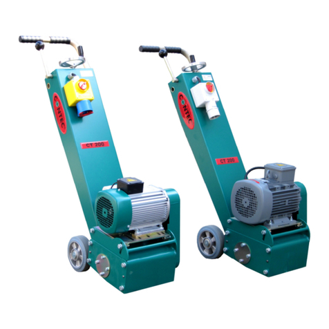
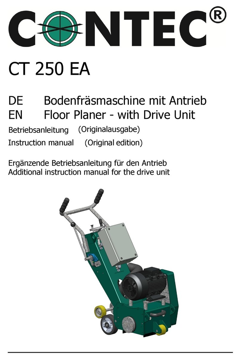
Contec CT 200 User manual

CT 200
Floor Planer
Instruction manual (USA)
________________________________________________________

Instruction manual CT 200
- 2 -
CONTEC
®
GmbH Hauptstrasse 146, 57518 Alsdorf, Deutschland/ Germany/ Allemagne © CONTEC
®
2011
info@contecnorthamerica.com, www.contecnorthamerica.com
Index
1. EU-Declaration of Conformity …3
2. Machine applications ...4
3. Technical Data ...4
3.1 Planer ...4
3.2 Tools ...4
4. Applications of the tools ...4
5. Safety rules ...4
6. Operating ...5
7. Changing the drum ...5
8. Adjusting the drum ...6
9. Maintenance and cleaning ...7
9.1 Bearings ...7
9.2 Height adjustment and joints ...7
9.3 Belt drive ...7
9.4 Cleaning ...7
10. Diagram ...7
11. Appendix ...9

Instruction manual CT 200
- 3 -
CONTEC
®
GmbH Hauptstrasse 146, 57518 Alsdorf, Deutschland/ Germany/ Allemagne © CONTEC
®
2011
info@contecnorthamerica.com, www.contecnorthamerica.com
Declaration of Conformity according to EN ISO/IEC 17050-1
EC-Declaration of Conformity
Month.Year: .
For the machine described below
Product denomination:
Model:
Serial number:
Floor Planer
CT 200
Herewith we declare, that the machine is complying with all the essential requirements of the
Machine Directive 2006/42/EC of the EUROPEAN PARLIAMENT of the 17th of Mai 2006
The person authorized to compile the relevant technical documentation (According to Appendix II Nr.
1. A. Nr. 2, 2006/42/EG):
Name, Surname: Greb, Johannes
Function: Technical Manager
Address: Neuer Weg 17, 57518 Alsdorf, Germany
More information on the compliance with the directive is contained in Appendix 1.
This Declaration is given by the manufacturer:
Name: Contec
®
Maschinenbau & Entwicklungstechnik GmbH
Address: Hauptstraße 146,57518 Alsdorf,Deutschland/Germany
Given by:
Name, Surname: Greb, Johannes
Function: Technical Manager
Alsdorf, 22.12.2010
Place/Date Signature
Appendix 1 of the Declaration of Conformity
Month.Year: .
For the machine described below
Product denomination:
Model:
Floor Planer
CT 200
Herewith we declare, that the machine is complying with all the essential requirements of the:
Directive 2004/108/EC of the EUROPEAN PARLIAMENT of the 15th of December 2004 on
Electromagnetic Compatibility
Directive 2006/42/EC of the EUROPEAN PARLIAMENT of the 17th of Mai 2006
Harmonised Standards used:
EN 12100 - 1 „Safety of Machinery – Basic concepts“
EN 12100 - 2 „Safety of Machinery – Technical principles”

Instruction manual CT 200
- 4 -
CONTEC
®
GmbH Hauptstrasse 146, 57518 Alsdorf, Deutschland/ Germany/ Allemagne © CONTEC
®
2011
info@contecnorthamerica.com, www.contecnorthamerica.com
2. Machine applications
Planing of horizontal, dry floors such as concrete and steel surfaces with or without a coating
and asphalt using CONTEC
®
planing tools. The use of the machine outside is only possible in
dry weather.
3. Technical Data
3.1 Planer
Width of cut 200 mm (8 in)
Width 36 cm (14 in)
Length 80 cm (31 in)
Height 97 cm (38 in)
Weight 52 kg (115 Ibs)
Dust port ¢ 50 mm (2.0 in)
Height adjustment Hand wheel and lever
Electric motor 1.1 kW (1.5 hp), 110 V, 60 Hz, 15 A
Honda petrol 5.5 hp
Other motors On request
Average value of acceleration a
hv
* 6,0 m/s
2
Noise level L
wa
* 107 dB(A)
Noise level Leq * 97 dB(A)
* Data: VÜA Verein zur Überwachung technischer Anlagen e.V.
3.2 Tools
Drum diameter 108 mm (4.4 in)
Cutter shaft diameter 12 mm (0.49 in)
Number of shafts 4
TCT Cutter 46/5
Milling cutter 46/20
Beam flails 46
Cutter diameter 46 mm (1.88 in)
All specifications are approximate and subject to confirmation. They should only be used as a
guide.

Instruction manual CT 200
- 5 -
CONTEC
®
GmbH Hauptstrasse 146, 57518 Alsdorf, Deutschland/ Germany/ Allemagne © CONTEC
®
2011
info@contecnorthamerica.com, www.contecnorthamerica.com
4. Applications of the tools
TCT Cutters Heavy duty, long life cutters for all concrete
texturing, scabbling, planing and grooving
applications. Also used for removal of road
markings, roof chippings and brittle coatings
Milling cutters Primarily for the removal of thermoplastic
road / runway markings. Tipped with tungsten
carbide they are cost effective and highly
efficient. A range of cutter dimensions are
available.
Beam flails Heat treated cutters for the removal of paint
coatings and laitance from new concrete. Also
for removing grease, dirt and ice deposits.
5. Safety rules
Attention ! The CT 200 floor planers are constructed according to existing safety rules and
regulations. These technical precautions should not be removed or changed
under any circumstances. While operating the machines the following points
should also be kept in mind:
1. The planers should always be operated with all safety covers and technical precautions.
2. The operator should never leave the machine during operation.
3. Before leaving the machine all rotary parts should be brought to a stand still. The electric
models must be disconnected from the mains. Make sure that the machine cannot roll or
move by itself.
4. After maintenance and adjustment all safety covers must be reattached.
5. If the noise level exceeds 90 dB(A) ear protectors must be worn.
6. In the event of a large amount of dust during operation connect a dust collector to the
planer.

Instruction manual CT 200
- 6 -
CONTEC
®
GmbH Hauptstrasse 146, 57518 Alsdorf, Deutschland/ Germany/ Allemagne © CONTEC
®
2011
info@contecnorthamerica.com, www.contecnorthamerica.com
6. Operating
a. After mounting the appropriate tools the operation of the planer can begin.
b. Lower the planer with the lever to the operating position. Turn the hand wheel of
the height adjustment until the tools are lowered to the floor and until you achieve
the required finish.
Attention: Lowering the tools too much decreases the performance of the machine. You
will also destroy the shafts in the drum and the bearings of the machine.
Attention: Never switch the motor of the planer on while the tools still touch the floor.
Always lift the machine and the tools clear from the floor and then switch the motor on.
c. Heavy dust can be avoided by connecting a dust collector to the dust port.
7. Changing the drum
Attention: Before any maintenance, the machine must be brought to a complete stand still.
Always disconnect the machine if it is an electric model.
-Lift the machine with the lever so that the tools are well clear of the floor.
-Unscrew the screws on the right side plate (M10, Key width 17 mm)
-Carefully remove the side plate.
-Take out the drum. Remove worn out tools. Check shafts and drums for wear and tear. If
necessary replace new tools on the drum.
-Push drum on freshly greased shaft.
-Reconnect side plate.

Instruction manual CT 200
- 7 -
CONTEC
®
GmbH Hauptstrasse 146, 57518 Alsdorf, Deutschland/ Germany/ Allemagne © CONTEC
®
2011
info@contecnorthamerica.com, www.contecnorthamerica.com
8. Adjusting the drum
During the operation of the CT 200 floor planer or after a drum has been changed or replaced,
the drum shaft and the rear wheel axis can fall out of alignment. This results in an uneven
track on the floor. On one side the drum touches the floor before the other and therefore
removes more surface material on this side.
One of the two rear wheels is mounted on an eccentric shaft (see diagram).
Rear wheel
Clamping screw
Clockwise
If the drum has to be adjusted proceed as follows:
Place the planer on an even floor. Lift the machine with the height adjustment hand wheel,
until all the tools are well clear of the floor. Loosen the clamping screw of the eccentric shaft.
On the other side of the rear wheel is a screw which keeps the wheel on the shaft. Turning the
screw will also turn the eccentric shaft. The floor planer moves up and down on one side.
Always turn the screw clockwise. Anti clockwise would loosens the screw. Keep turning until
all the tools on the drum are the same distance to the floor. Tighten the clamping screw again.

Instruction manual CT 200
- 8 -
CONTEC
®
GmbH Hauptstrasse 146, 57518 Alsdorf, Deutschland/ Germany/ Allemagne © CONTEC
®
2011
info@contecnorthamerica.com, www.contecnorthamerica.com
9. Maintenance and cleaning
9.1 Bearings
All bearings are greased for their life time.
9.2 Height adjustment and joints
All joints have to be greased periodically with a standard machine grease.
9.3 Belt drive
Check the belts after approximately every 30 hours of operation. To tension the belt you need
to raise the motor bracket. Loosen the 4 M10 screws of the bracket. The front screws are in
two slots. Raise the bracket until the belts are tensioned. Tighten the screws again.
9.4 Cleaning
Regular cleaning of the machine increases the life of all components and tools of the planer.
10. Diagram
Handle bar
Lever
Height adjustment hand wheel
On- Off switch for electric models
Motor
Rear wheel
Front wheel
Left side plate
11. Appendix
Diagrams
Wire diagram
Tools
Part list


CT 250 Stückliste/ PartsList
Artikel-Nr. / Part-No.
Description 1
Description 2
D-Nr
WeightKG
17-10-05-01 Right Side CoverBearing Housing CT200 1 0,20
61-20-60-06 Bearing forright Bearing Housing CT200 and forSideplanerCT 60 3 0,13
17-17-05-02 Right Bearing Housing CT200 5 0,40
61-30-00-30 Circlipforright side Bearing Housing CT200/CT60 6 0,00
17-21-07-02 Hexagon Insidering Bearing Housing MainAxisand Side PlanerCT200 7 0,07
17-21-07-01 DriveShaft heavyDutyCT200 9 2,05
61-30-01-47 Circlipforleft side Bearing Housing CT200 10 0,00
61-20-60-05 Bearing forleft Bearing Housing CT200 11 0,09
17-10-07-03 DistanceRing Bearing Housing CT200 13 0,03
17-17-06-01 Left Bearing Housing CT200 15 0,99
90-24-95-3TB DrumPulleyCT200 17 1,04
90-24-16-10-25 Taperlock DrumCT200 19 0,37
17-10-04-01 Belt CoverCT200 21 1,28
70-24-10-710 Belt ElectricCT200 23 0,06
70-24-10-737 Belt PetrolHonda CT200 23 0,06
70-24-10-750-US Belt USVersion onlyfor3HPMotorCT200 23 0,07
90-24-63-3TB MotorPulleyCT200 25 0,47
90-24-11-08-24 Taperlock Motor2KVA,230 Volt CT200 27 0,11
90-24-11-08-28 Taperlock Motor3KVA, 400 Volt CT200 27 0,09
90-24-11-08-3HP-US Taperlock MotorCT200 3HPUSVersion 27 0,08
90-24-11-08-Honda Taperlock MotorHonda 5,5HPCT 200 27 0,14
55-03-00-20 Motor2KVA, 230 Volt, 50 HZ, Elephant 29 26,00
55-03-00-30 Turbine Motor3KW, 400 Volt CT 200/ Tornado/Elephant 29 27,00
55-03-23-40 Turbine Motor3KW, 230 Volt 3-Phase CT200/Tornado/Elephant 29 27,00
56-GX-160-K1-4 Motor5,5HPforCT200 29 0,00
17-10-10-01 Bracket forSingleFaseMotorCT200 31 0,35
17-10-10-01-US-H RearBracket forSingleFaseMotor 230 Volt USVersion CT 200 31 0,44
17-10-10-01-US-V Front Bracket forSingleFaseMotor 230 Volt USVersion CT 200 31 0,44
17-10-10-02-US Bracket forSingleFaseMotor230 Volt USVersion CT 200 31 0,43
17-10-02-01 Mounting PlateMotorCT200 33 2,00
17-10-01-00 Machine FrameCT200 35 27,00
17-10-01-02 Ride Side PlateMachine FrameCT200 37 0,00
80-20-60-40 Front WheelCT200 39 0,19
70-23-02-30 RubberSealing CT200 41 0,06
Seite1von 3

CT 250 Stückliste/ PartsList
17-10-11-01 Bracket forRubberSealing CT200 43 0,30
17-10-09-01 LevelAdjustment Back WheelCT200 45 0,80
60-33-12-25 Connecting Pinforlifting Rod CT 200 46 0,00
30-10-08-05 Axisout ofcentreRearWheelCT 200 47 0,38
30-10-08-04 AxisRearWheelCT200 49 0,33
80-20-31-60 RearWheelCT200/M200 51 1,14
17-10-08-03 Height Adjustment Pipe CT200 53 1,05
17-10-08-02 Height Adjustment ScrewCT200 55 0,45
61-50-10-40 EyeScrwforQuick LeverCT 200 57 0,04
17-10-08-01 HolderforSpindleCT200 59 0,18
90-21-45-12 GolfBall CT200 60 0,07
17-10-13-01 HandleHeight Adjustment CT200 61 0,40
90-21-95-51 Revolving PinforHandwheelCT 200 62 0,08
90-21-95-50 LevelAdjustment WheelCT200 63 0,38
50-20-10-20-K Switch-Socket-Combination Omega/CT200 forMotor2KW, 230 Volt, 50 HZ 65 0,50
50-20-10-30-K Switch-Socket-Combination Omega/CT200 forMotor3KW, 400 Volt, 50 HZ 65 0,63
18-10-07-01 HandlecompleteOmega/CT200 67 1,40
70-21-26-10 RubberGripclosed Side CT 200 69 0,06
70-21-26-11 RubberGripopen Side CT 200/Omega 71 0,06
51-10-10-01 SwitchBoxForMotorProtective CT200 81 0,00
51-20-30-01-US LowVoltage ProtectiveCT200 US-Version 120 Volt, 60 HZ 83 0,00
51-10-0-20-US SwitchMotorProtectiveCT200 110 Volt 1,5HPor230 Volt 3HPUSVersion 85 0,00
18-10-01-05 HandleArmCoverOmega/CT200 93 0,88
95-16-45-05 Tungston Carbide Cutters45 / 5CT200 101 0,04
95-16-42-10 Milling Flail Cutters42 / 10 CT200/350 103 0,08
95-16-42-12 SteelCuttersBeamFlails42 / 12 CT 200 / CT 350 105 0,01
95-16-24-13 SpacerCT200/350 107 0,01
95-10-200-A AxisforDrumCT200 109 0,19
18-10-01-08 Cover110 VforSwitchOmega/CT200 286,00
472-47 0,00
50-10-11-16 230 Volt Plug CT 200 0,00
50-20-20-14 Reverseplug 16 A, 400 Volt CT 200 0,00
50-25-11-30 Kabelbetween Plug / Switch2KW 230 Volt CT 200 0,00
50-25-11-31 Kabelbetween Switch/ Plug 3KW 400 Volt CT200 0,00
50-25-11-32 Kabelbetween Motor/ Switch230 Volt 2KWCT 200 0,00
50-25-11-33 Kabelbetween Motor/ Switch400 Volt 3KWCT 200 0,00
Seite2von 3

CT 250 Stückliste/ PartsList
51-20-30-01 MotorProtective2KVA, 230 Volt CT200 0,00
51-20-30-02 MotorProtective3KW, 400 Volt CT200 0,00
51-20-30-03 LowVoltage Protective400 Volt CT200 0,00
51-20-30-04 LowVoltage Protective230 Volt CT200 0,00
55-03-00-21 VentilatorCoverforMotor2KVA, 230 V Elephant/CT200 420,00
55-03-00-22 KondenserMotor2KWEMG CT 200 0,50
55-03-00-23 KondenserMotor2KWEMG CT 200 0,50
55-03-04-20 Motor2KVA, 230 Volt, 50 HZ, Elephant 19,30
56-160-10 KeyforMotor5,5HPCT200 0,00
56-160-K1-5 Side Exaust forMotorCT200 0,00
90-24-11-08-1,5HP-US Taperlock MotorCT200 1,5HP115 Volt USVersion 130,00
95-10-200-42-10-K CompleteDrumwithMilling Flails42/10 40 PiecesCT 200 7,65
95-10-200-42-12-K CompleteDrumwithSteelBeamFlails 42/12 CT 200 6,95
95-10-200-K CompleteDrumwithtiped Tungston Cutter CT 200 7,75
95-10-200-T DrumforCT200 3,55
95-16-10-200 WireBrushCT 200 0,00
95-16-42-10-40 Set Milling Flail Cutters42 / 10 CT200 1 Set =40 Pieces 3,04
95-16-42-12-124 SteelCuttersBeamFlails42 / 12 CT 200 1Set =124 pieces 1,49
95-16-45-05-76 Set Tungston Carbide Cutters45 / 5 CT 200 1Set =76 Pieces 2,89
95-16-45-06 Tungston Carbide Cutters45/6CT200/350 44,00
95-16-45-06-76 Set Tungston Carbide Cutters45/6CT200 1 Set =76 Pieces 3,44
Seite3von 3
Other manuals for CT 200
2
Table of contents
Other Contec Planer manuals