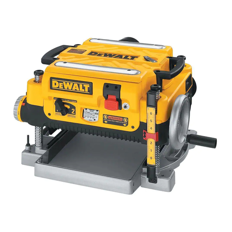
DeWalt DW735 User manual

If you have questions or comments, contact us.
Pour toute question ou tout commentaire, nous contacter.
Si tiene dudas o comentarios, contactenos.
INSTRUCTION MANUAL
GUIDE D'UTILISATION
MANUAL DE INSTRUCCIONES
INSTRUCTIVODE OPERACION,CENTROS DE SERVICIOY P©LIZA DE
GARANT/A. ADVERTENCIA: LE_s,SE ESTE INSTRUCTIVOANTES DE
USAR EL PRODUCTO.
E ®
DW735
13" (325 mm) Heavy-Duty Portable Thickness Planer
Raboteuse portative &service intensif 13 po (325 mm)
Cepilladora port_til para trabajo pesado de 13" (325 mm)

IF YOU HAVE ANY QUESTIONS OR COMMENTS ABOUT THIS OR
ANY DFWALT TOOL, CALL US TOLL FREE AT:1-800-4-DEWALT
(1-800-433-9258)
SAVE THESE INSTRUCTIONS
Important Safety Instructions for All Tools
_ARNING: For your own safety, read the instruction manual before
operating the planer. Failure to heed these warnings may result in
personal injury and serious damage to the planer. When servicing this
tool, use only identical replacement parts. Have damaged cords
replaced by an authorized service center.
DOUBLE INSULATION
Double insulated tools are constructed throughout with two separate
layers of electrical insulation or one double thickness of insulation
between you and the tool's electrical system. Tools built with this
insulation system are not intended to be grounded. As a result,
your tool is equipped with a two prong plug which permits you
to use extension cords without concern for maintaining a ground
connection.
NOTE: Double insulation does not take the place of normal safety
precautions when operating this tool The insulation system is for
added protection against injury resulting from a possible electrical
insulation failure within the tool
POLARIZED PLUGS
To reduce the risk of electric shock, this equipment has a polarized
plug (one blade is wider than the other). This plug will fit in a polarized
outlet only one way. If the plug does not fit fully into the outlet, reverse
the plug. If it still does not fit, contact a qualified electrician to install
the proper outlet. Do not change the plug in any way.
WARNING: When using electric tools, basic safety precautions
should always be followed to reduce the risk of fire, electric shock,
and personal injury, including the following:
General Safety Instructions
• KEEP GUARDS IN PLACE and in working order.
•REMOVE ADJUSTING KEYS AND WRENCHES. Form habit
of checking to see that keys and adjusting wrenches are removed
from tool before turning it on.
•KEEP WORKAREA CLEAN. Cluttered areas and benches invite
injuries.
•DON'T USE IN DANGEROUS ENVIRONMENT. Don't use
power tools in damp or wet locations, or expose them to rain.
Keep work area well lighted. Always operate tool in a web
ventilated area free of combustible materials, gasoline or solvent
vapors. Ifsparks come in contact with flammable vapors, they may
ignite, causing fire or explosion.
•KEEP CHILDREN AWAY. All visitors should be kept safe
distance from work area.
• MAKE WORKSHOP KID PROOF with padlocks, master
switches, or by removing starter keys.
•DON'T FORCE TOOL. It will do the job better and safer at the
rate for which it was designed.
•USE RIGHT TOOL. Don't force tool or attachment to do ajob for
which it was not designed.
•USE PROPER EXTENSION CORD. Make sure your extension
cord is in good condition. When using and extension cord, be sure
to use one heavy enough to carry the current your product will
draw. An undersized cord will cause a drop in line voltage resulting
in overheating and loss of power. The following table shows the
correct size to use depending on cord length and nameplate
ampere rating. Ifin doubt, use the next heavier gauge. The smaller
the gauge number, the heavier the cord. When operating a power
tool outside, use an outdoor extension cord marked "W-A" or
"W." These cords are rated for outdoor use and reduce the risk of
electric shock.

Minimum Gauge for Cord Sets
VoltsI Total Lengthof Cord in Feet(meters)
Ampere Rating 120V 25 (7.6) 50 (15.2) 100 (30.5) 150 (45.7)
240V 50 (15.2) 100 (30.5) 200 (61.0)300 (91.4)
More Not More AWG
Than Than
0 6 18 16 16 14
6 10 18 16 14 12
10 12 16 16 14 12
12 16 14 12 NotRecommended
WEAR PROPER APPAREL. Do not wear loose clothing, gloves,
neckties, rings, bracelets, or other jewelry which may get caught in
moving parts. Nonslip footwear is recommended. Wear protective
hair covering to contain long hair. Air vents often cover moving
parts and should also be avoided.
ALWAYS USE SAFETY GLASSES. Also use face or dust mask
it cutting operation is dusty. Everyday eyeglasses only have impact
resistant lenses, they are not safety glasses.
ACTUATING TOOL MAY RESULT IN FLYING DEBRIS,
COLLATION MATERIAL, OR DUST WHICH COULD HARM
OPERATOR'S EYES. The operator and all those persons in
the general area should wear safety glasses with permanently
attached side shields. Approved safety glasses are imprinted
with the characters "Z87.1 ". It is the employer's responsibility to
enforce the use of eye protection equipment by the tool operator
and other people in the work area.
SECURE WORK. Use of clamps or a vise to hold work when
practical. It's safer than using your hands and it frees both hands
to operate tool.
DON'T OVERREACH. Keep proper footing and balance at all
times.
MAINTAIN TOOLS WITH CARE. Keep tools sharp and clean
for best and safest performance. Follow instructions for lubricating
and changing accessories.
•DISCONNECT TOOLS before servicing; when changing
accessories, such as blades, bits, cutters, and the like.
•REDUCE THE RISK OF UNINTENTIONAL STARTING. Make
sure switch is in off position before plugging in.
•USE RECOMMENDED ACCESSORIES. Consult the
instruction manual for recommended accessories. The use of
improper accessories may cause risk of injury to persons.
•NEVER STAND ON TOOL. Serious injury could occur if the tool
is tipped or if the cutting tool is unintentionally contacted.
•CHECK DAMAGED PARTS. Before further use of the tool, a
guard or other part that is damaged should be carefully checked
to determine that it will operate properly and perform its intended
function-check for alignment of moving parts, binding of moving
parts, breakage of parts, mounting, and any other conditions that
may affect its operation. A guard or other part that is damaged
should be properly repaired or replaced.
•DIRECTION OF FEED. Feed work into planer according to
direction of feed arrows on top of the unit.
•NEVER LEAVE TOOL RUNNING UN ATTENDED. TURN
POWER OFF. Don't leave tool until it comes to a complete stop.
Additional Specific Safety Rules for
Planers
•To reduce the risk of injury, user must read and understand
instruction manual before operating planer.
•Always wear eye protection and dust mask if necessary.
•Keep hands away from the underside of the cutter head carriage.
•Never clear clogs, make cutter knife replacement, or any other
repairs/adjustments with unit plugged in.
•Make certain that the switch is in the OFF position before
connecting plug to a power source.

•Be sure that the cutter knives are mounted as described in the
instruction manual and check that all bolts are firmly tightened
before connecting unit to power source.
• To avoid injury, never rotate the cutter block directly with your
hands.
• Keep guards in place and in good working order.
• Stay alert -never operate the unit when tired or under the
influence of drugs, alcohol, or medication.
• Do not use in dangerous environments. Do not use near
flammable substances, in damp or wet locations, or expose to
rain.
• Never plane material which is shorter than 12 inches.
• Exhaust chute: remove shavings with brush or vacuum after
power has been shut off and cutter head has stopped rotating.
• ALWAYS LOCATE PLANER WITH PROPER CLEARANCE ON
THE OUTFEED SIDE of the unit to prevent pinching or binding of
the workpiece against any obstacle.
•Clean out your tool often, especially after heavy use. Dust
and grit containing metal particles often accumulate on interior
surfaces and could create a risk of serious injury, electric shock or
electrocution. ALWAYS WEAR SAFETY GLASSES.
WARNING: For your own safety, it is recommended that two
people carry this machine or serious injury could result.
WARNING: Always wear proper personal hearing protection
that conforms to ANSI $12.6 ($3.19) during use. Under some
conditions and duration of use, noise from this product may
contribute to hearing loss.
WARNING: Some dust created by power sanding, sawing,
grinding, drilling, and other construction activities contains chemicals
known to the State of California to cause cancer, birth defects or
other reproductive harm. Some examples of these chemicals are:
• lead from lead-based paints,
• crystalline silica from bricks and cement and other masonry
products, and
• arsenic and chromMm from chemically-treated lumber.
Your risk from these exposures varies, depending on how often you
do this type of work. To reduce your exposure to these chemicals:
work in a well ventilated area, and work with approved safety
equipment, such as those dust masks that are specially designed to
filter out microscopic particles.
•Avoid prolonged contact with dust from power sanding,
sawing, grinding, drilling, and other construction activities.
Wear protective clothing and wash exposed areas with
soap and water. Allowing dust to get into your mouth, eyes, or
lay on the skin may promote absorption of harmful chemicals.
WARNING: A dust mask or respirator should be worn by all
persons entering the work area. The filter should be replaced daily or
whenever the wearer has difficulty breathing. See your local hardware
store for the proper NIOSH/OSHA approved dust mask.
• The label on your tool may include the following symbols. The
symbols and their definitions are as follows:
V......... volts
Hz....... hertz
min ..... minutes
---... direct current
_) ....... Class I Construction
(grounded)
[] ....... Class II Construction
(double insulated)
.../min per minute
A.......amperes
W......watts
, ..... alternating current
_, ..... alternating or direct current
no......no load speed
......earthing terminal
..... safety alert symbol
BPM.. beats per minute
RPM.. revolutions per minute

Specifications
Input ....................... 120 V AC '_, 15 Amp
No load speed ........10,000 RPM
Feed speed ............ 14 ft. per minute or 26 ft. per minute

Planing height ......... Maximum 6", Minimum 1/8"
Planing width .......... Maximum 13"
Planing depth ......... Maximum 1/8" (for boards 6" wide or less)
Electrical Connection
Be sure your power supply agrees with the nameplate marking. Volts,
50/60 Hz or "AC only" means your planer must be operated only with
alternating current and never with direct current. Voltage decrease of
more than 10% will cause loss of power and overheating. All DEWALT
tools are factory tested, if this tool does not operate, check the power
supply.
Transporting the Planer
j_ WARNING: For your own safety, it is
recommended that two people carry this
machine or serious injury could result.
When moving your planer, carry it either
by the side carrying handles (A) or by the
handles at the base of the planer (B). When
transporting or storing the planer, use the
cord wrap located in the back of the tool (C)
to keep the cord in place.
Bench Mounting
To facilitate bench mounting, two different sized holes (D)are provided
on the four corners of your planer. If mounting the planer with bolts,
use the larger holes. If mounting the planer with nails or screws, use
the smaller holes. It is not necessary to use both sets of holes.
Always mount your planer firmly to prevent movement. To enhance
the tool's portability, it can be mounted to a piece of 1/2" (12.7mm) or
thicker plywood which can then be clamped to your work support or
moved to other job sites and reclamped.
NOTE" If you elect to mount your planer onto a piece of plywood,
make sure that the mounting screws don't protrude from the bottom
of the wood. The plywood must sit flush on the work support.
_CAUTION: The mounting surface should not be warped or
otherwise uneven. -_
ASSEMBLY E ....
_WARNING: DO NOT REMOVE GUARDS(E). Serious injury could result.
A_WARNING: Toreduce the risk of serious
personal injury, turn tool off and
disconnect tool from power source before
making any adjustments or removing/
installing attachments or accessories.
TO A'rI'ACH THE DEPTH ADJUSTMENT ©
CRANK HANDLE
1. Remove the screw located in the crank
handle shaft.
2. Insert the crank handle (F) over the shaft.
3. Secure in place with the screw and
T-wrench (G) provided. B
DUST EJECTION PORTS
Your planer comes with a dust ejection port. The round port (I) as
shown below is for use with a 4" dust collector hose.
TO SET UP DUST EJECTION
1. Select the port (I).
2. Depress the lock button (K)on the chip ejection chute (H).

3.Slidethenotchesinthedustportoverthepinsonthechip
ejectionchute.
4.Rotatetheportuntilthebuttonengagesthedustejectionchute
andlocksinplace.
,_WARNING: DO NOT OPERATE YOUR PLANER WITHOUT THE
DUST EJECTION PORT LOCKED INTO PLACE. DO NOT INSERT
ANYTHING INTO THE DUST EJECTION CHUTE UNLESS THE
PLANER IS UNPLUGGED AND YOU ARE CLEARING A CLOG OR
OBSTRUCTION IN THE UNIT. DO NOT GET YOUR FACE OR EYES
NEAR THE DUST EJECTION PORT WHEN THE PLANER IS IN
OPERATION. SERIOUS INJURY COULD RESULT.
WARNING: Chips are ejected at significant velocity. Keep hands
and face clear of dust ejection port.
TO REMOVE THE DUST EJECTION PORT
1. Use the T-wrench to depress the lock button on the dust chute.
2. Twist the port until the pins are disengaged from the notches on
the port.
3. Pull the dust ejection port off of the dust chute.
OPERATION
_WARNING: To reduce the risk of serious personal injury,
turn tool off and disconnect tool from power source before
making any adjustments or removing/installing attachments
or accessories.
On/Off Switch
To turn the planer on, lift the switch (L) up.
The planer locks on automatically. To turn the
tool off, press the switch down. A hole is
provided under the switch (M) for insertion of a
padlock to lock off the planer.
Depth Adjustment
DEPTH ADJUSTMENT SCALE
The depth adjustment scale (N), located
on the right front of your planer, indicates the
finished thickness of your workpiece. One
rotation of the depth adjustment crank is equal
to 1/16", half rotation is equal to 1/32", etc.
DEPTH ADJUSTMENT CRANK
Turning the crank clockwise lowers the cutter
head. Turning the crank counterclockwise raises
the cutter head.
Material Removal Gauge
Your planer is equipped with a material
removal gauge (O). It is used to indicate the
amount of wood that will be removed in one
pass with the carriage set at its current
height.
TO USE THE MATERIAL REMOVAL
GAUGE
1. Slide approximately 3" of your material under the middle of the
carriage.
2. Be sure the wood is lying flat against the base of the planer.
If the material is inserted at an angle, the reading may be
inaccurate.

3.Crankthecarriagedownonthematerialuntilthematerialremoval
barengagesthewood.Youwillseetheredarrowbegintomove
upthescaleindicatingtheamountofmaterialtoberemovedwith
thecarriageatthatheight.
4.Adjustthecarriageheightuntilthedesireddepthofcutappears
onthegauge.
5.Pullthematerialoutfromunderthecarriage.
6.Turntheunitonandfeedyourmaterialintothecutterhead.
NOTE: Do not exceed the recommended depth of cut for various
widths of material recommended on the material removal gauge.
J_,WARNING: DO NOT SWITCH THE UNIT ON WITHTHE MATERIAL
POSITIONED UNDER THE CARRIAGE, SERIOUS INJURY COULD
RESULT.
Speed Selection
NOTE: ONLY SWITCH SPEEDS WHEN THE PLANER IS RUNNING.
Your planer has the ability to feed material
at two different speeds. The two-speed P
feature (P) was designed to improve
efficiency when planing and to provide the
best possible surface finish to a variety of
materials.
To remove material thickness more quickly,
set the unit at speed "2". This setting delivers 96 cuts per inch to the
material.
For finishing, set the unit to speed "1". Speed "1" is ideal for ensuring
the finest finish on the last pass before your final thickness isachieved.
NOTE: When planing particularly hard or figured species of wood,
speed "1" is recommended. The slower feed rate will reduce knife
wear and tear-out by delivering 179 cuts per inch to the material.
Fan-Assisted Chip Ejection System
Your planer is equipped with a fan-assisted chip ejection system to
aid in exhausting chips from the unit. The fan-assisted chip ejection
system will work in conjunction with independent dust collection
systems.
NOTE: It is not recommended that a shop vac be connected to the
DW735. The capacity of most vacs does not support the volume of
chips ejected during planing. The vacuum hose may clog stopping
the flow of chips.
See the Troubleshooting Guide, page 14, for additional information.
Automatic Carriage Lock
There is no manual carriage lock on your planer. A device that
automatically minimizes the movement that causes snipe during
planing is designed into the four threaded posts.
Turret Stop
Your planer is equipped with a turret stop (Q) for
repetitive planing at pre-set depths. Stops are set Q
at 1/8", 1/4", 1/2", 3/4", 1", and 1-1/4".
TO SET THE MINIMUM DEPTH TO WHICH
THE CARRIAGE CAN TRAVEL WITH THE
TURRET STOP
1. Be sure the carriage is set above 1-1/4" before
trying to set the turret stop.
2. Turnthe dial on the front leftof the planer until the desired thickness
setting aligns with the red indicator then lower the carriage.
3. Plane the workpiece at desired increments until the correct final
thickness is achieved.
NOTE: DO NOT USE FORCE TO CRANK THE CARRIAGE BELOW
THE LEVEL THAT THE TURRET STOP INDICATES. PERMANENT

DAMAGETOTHEHEIGHTADJUSTMENTSYSTEMONYOUR
PLANERWILLRESULT.
PLANING BASICS
Proper Planing Technique
TO PLANE YOUR MATERIAL
1. Lower the carriage to the desired height for your first pass.
2. Turn the unit on and feed the material into the feed rollers.
3. Examine the finished cut and adjust the carriage to the
appropriate height for your next pass.
NOTE: Flip the board back and forth between each pass as
recommended in Proper Planing Techniques.
See the Troubleshooting Guide, page 14, for additional information.
_WARNING: DO NOT TURN THE UNIT ON WITH THE MATERIAL
ALREADY INSERTED UNDER THE CARRIAGE. WAIT UNTIL THE
ROLLERS AND CUTTER HEAD ARE UP TO FULL SPEED BEFORE
FEEDING YOUR MATERIAL INTO THE MACHINE.
For best results, plane both sides of the workpiece to reach a
desired thickness. For example, if you need to remove 1/8" from
your workpiece, remove 1/16" from each side. This not only allows
the workpiece to dry with a even moisture content, it also produces
finer cuts.
AWARNING: Plane only wood that is free from foreign objects, with
no loose knots and as few tight knots as possible. Do not plane wood
that is severely warped, twisted, knotted or bowed.
_WARNING: Do not place your body between the rear of the planer
and a stationary object while material is feeding. Serious injury could
result.
MINIMUM/MAXIMUM WIDTH/HEIGHT/DEPTH
NOTE: Always plane in the direction of the grain. Support the
workpiece adequately at all times. Planing material less than 3/4"
wide is not recommended. If you must
plane narrow material, group several
pieces together and plane them as one
wide workpiece whenever possible.
The maximum depth of cut your planer
can take in one pass is 1/8" (on material
less than 6" wide). Never attempt to
modify your planer to take a deeper cut.
Follow the recommended depth/width of
cut guidelines shown in Table A for best
results.
Snipe
TABLE A
/y, MMERIAL r_ _
_ i I REMOVAL i
i f_-I GAUGE _J
_ C3DEPT j
__ °FcuTi
3" 6" 9" 13" _-
Snipe is a depression made when an unsupported end of your
material drops toward the floor, causing the opposite end to lift up
into the cutter head.
TO AVOID SNIPE
Feed the workpiece into the planer so it is level and remains flat
against the base at all times.
Keep the workpiece level throughout planing operation by receiving
or "catching" it from the rear of the planer.
If you are planing material that is especially long, the use of
additional material support is recommended.
Twisted, Cupped and Bowed Wood
If both sides of your material are very rough or if the material is
cupped, bowed or twisted, your planer may not produce the desired
result. Ideally, you should have at least one level face/surface on
your material before you plane. Your thickness planer will work best
with material that has been run through a jointer to produce one flat
surface. If you do not have at least one flat surface or a jointer, see
the following recommendations.

TO PLANE TWISTED WOOD
WARNING: TWISTED WOOD MAY
JAM YOUR THICKNESS PLANER. IF A JAM
OCCURS, TURN THE POWER OFF,
DISCONNECT THE POWER SUPPLY AND RAISE THE CARRIAGE
TO RELEASE THE MATERIAL FROM THE CUTTER HEAD.
If your material is only slightly twisted:
Plane both sides alternating from one to the other until the desired
thickness is reached.
TO PLANE CUPPED WOOD
To obtain the best possible results with
cupped wood:
Rip the material down the middle and plane it as two separate pieces.
Ripping the material reduces the severity of the cup and allows
the machine to deliver better results. Understand that you will have
to remove more material on cupped wood to achieve the desired
thickness than you would on a normal board.
If ripping the material is not an option:
Plane one side of the material until flat, then plane the opposite side
until it is also flat.
NOTE: Do not flip the board back and forth between each pass as
recommended by the general planing directions.
TO PLANE BOWED WOOD
The feed rollers and cutter head in your planer will push the bow out
of the material as it feeds. However, when the material exits the
planer, the pressure of the rollers TOPFLAT
and cutter head will release allowing
the wood to spring back into a
bowed formation. To properly
remove the bow, use ajointer. BOqq-OMFLAT
BOWED WOOD WILL BE
FLAq-I-ENEDBY FEED ROLLERS
AND CUTI-ER HEAD...
... BUT BOW WILL RETURN
AFTER WOOD IS PLANED
Changing the Planer Knives
AWARNING: DISCONNECT THE PLANER FROM THE POWER
SOURCE BEFORE ATTEMPTING TO CHANGE OR ACCESS THE
KNIVES.
TO CHANGE PLANER KNIVES
1. Use the T-wrench to remove the four screws in the top of the
planer.
2. Lift the top off (Fig. 1) and place it aside.
3. Remove the three wing nuts that seal the dust shroud over the
cutter head.
4. Rotate the dust shroud up so the round connection that locks
onto the fan housing is in the open position (Fig. 2).
5. Push the dust shroud to the left so it disengages from the fan
housing.
6. Take the dust shroud out of the unit (Fig. 3) and set it aside.
7. The cutter head is now exposed.
If the eight screws in the cutter head clamp are not visible, use
a piece of scrap wood to carefully rotate the cutter head (Fig. 4)
until the screws are accessible and the cutter head lock lever (R)
engages. This will prevent further rotation of the cutter head as
you change the knives.
._WARNING: KEEP YOUR FINGERS AWAY FROM THE
CUTTER HEAD AT ALL TIMES. USE THE TOOL PROVIDED TO
HANDLE THE KNIVES.

FIG. 1
FIG. 3
FIG.5
FIG. 2
FIG. 6
8. Use the T-wrench to remove the eight screws on the knife clamp
and set them in the small screws bin (S) on the front panel of the
planer (Fig. 5).
9. Use the magnets on the top of the T-wrench to attract the knife
clamp and lift it off of the cutter head. One of the knives should
now be exposed.
10. Use the magnet (T)on the top of the T-wrench (Fig. 6) to attract
the knife. Avoid touching it with your fingers.
If only one side of the knife is worn:
1. Turn the knife around so that the sharp, unused edge hangs over
the end of the cutter head where it will cut the material. Be sure
to set the oblong holes inthe knife over the pins machined on the
cutter head.
2. Reset the knife clamp over the knife. Be sure to align the beveled
edge on the clamp with the sharp, cutting edge of the knife. If
these are not aligned correctly, the clamp will not secure the knife
properly.
3. Install the screws into the clamp and tighten sufficiently.
To access the other two knives:
1. Depress the cutter head lock lever (R)as shown in Figure 4.
2. Use the piece of scrap wood to carefully turn the cutter head until
it locks into place revealing another knife clamp.
3. Follow the same knife change procedure indicated above.
4. Repeat the procedure for the last dull knife.
After installing new knives:
1. Insert the round end of the dust shroud into the fan housing and
rotate it down to lock it into place.
2. Place the three wing nuts back into the shroud.
3. Screw the top cover of the planer back onto the unit.
NOTE: THE PLANER WILL NOT OPERATE IFTHE TOP COVER IS
NOT PLACED CORRECTLY.

MAINTENANCE
_WARNING: To reduce the risk of serious personal injury,
turn tool off and disconnect tool from power source before
making any adjustments or removing/installing attachments
or accessories.
Brush Change
Your planer is equipped with brush caps
(U) that are external to the motor. If your
brushes need to be replaced, begin by
acquiring a new set from a DEWALTservice
center or a dealer authorized to service
DEWALT products. Use only identical
DEWALTbrushes.
TO REPLACE THE BRUSHES ON YOUR PLANER
1. Use the T-wrench to remove the
top cover and brush cover screen on the
planer.
2. Use a flathead screwdriver to unscrew
the brush cap located in the right, rear of
the unit (V).
3. Do the same for the brush cap located V
on the side of the motor, inside the planer
cover.
4. Place the new brushes into the brush holders.
5. After installing the brushes, replace the top cover and brush cover
screen.
6. Before using the planer, run the unit for 10 minutes to seat new
brushes.
NOTE: Ifexisting brushes do not need replacing, be sure to maintain
the same orientation when you reinstall them.
10
Calibrating the Depth Adjustment Scale
The depth adjustment scale (N) on your planer is set at the factory.
However, with extended use, the depth adjustment scale could show
an incorrect measurement.
To check the depth adjustment scale,
plane a piece of scrap wood, noting
the measurement on the depth
adjustment scale.
Measure the finished thickness of
the workpiece. If the thickness of the
workpiece does not match the reading
on the depth adjustment scale, loosen
the two screws (W)on the red indicator.
Adjust the pointer up or down until its
reading matches the finished thickness
of the workpiece. Securely re-tighten
the screws.
Base Maintenance
Keep the table clean and free from oil, grease, and pitch. Treat the
table with paste wax to help maintain its smooth finish.
Circuit Breaker Reset Button
Your planer is equipped with an 18 amp
circuit breaker. If your planer becomes
overloaded and stops operating, turn off the
planer, let the unit sit for 2 minutes and press
the reset button (X) before you resume
working.
_WARNING: To prevent the planer from
starting unexpectedly if power is interrupted by
a circuit breaker trip, make sure the switch is in the OFFposition before
restoring power.

NOTE: Circuit breaker overload is often the result of dull knives.
Change your knives on a regular basis to avoid tripping your
breaker. Check your knives before re-setting the circuit breaker and
continuing to plane.
See the Troubleshooting Guide on page 14 for additional information
on circuit breaker trips.
Replacing the Drive Belt
Drive belts are available at extra cost at DEWALT authorized service
centers. Replacement of the drive belt should be performed by
qualified service personnel.
Chip Ejection Fan
The chip ejection fan on your planer should
be cleaned or cleared of debris periodically.
NOTE: TURN OFF AND UNPLUG THE PLANER
PRIOR TO ACCESSING THE CHIP EJECTION
FAN.
TO ACCESS THE FAN
1. Remove the top cover of the planer with the T-wrench.
2. Remove the dust shroud (Fig. 2, 3) and place it aside.
3. Remove the screws around the fan housing.
4. Remove the fan housing and place it aside as shown. The fan will
now be exposed for cleaning.
See the Troubleshooting Guide, page 14, for additional information.
AWARNING: Be sure to properly attach the fan housing and
assemble the shroud and top cover correctly before using your planer
again.
Accessories
_WARNING: Since accessories, other than those offered by
DEWALT, have not been tested with this product, use of such
accessories with this tool could be hazardous. To reduce the risk of
injury, only DEWALT,recommended accessories should be used with
this product.
Recommended accessories for use with your tool are available at
extra cost from your distributor or local service center.
Four accessories are available for the DW735 Thickness Planer.
• DW7350 Mobile Stand
• DW7351 Folding Tables
• DW7352 13" Knives
• DW7353 Chip Ejection Accessory
If you need any assistance in locating these accessories, please
contact DEWALTIndustrial Tool Co., 701 East Joppa Road, Baltimore,
MD 21286 or call 1-800-4-DEWALT (1-800-433-9258) or www.
dewalt.com
DW7351 Accessory Folding Tables
AWARNING: For your own safety, read the tool instruction manual
befc_re attaching the tables. Failure to heed these warnings may
result in personal injury and serious damage to the planer and the
accessory, When servicing this tool, use only identical replacement
parts. Have damaged cords replaced by an authorized service
center.
Your DW7351 folding table box should include:
2 folding tables 4 cap screws
4 springs 4 nuts
4 stepped bolts
SET-UP AND INSTALLATION OF BASE
HARDWARE
1. Place planer on a secure table or workbench. Position planer so
the front 3-4" of the base can be accessed from the underside.
2. Secure the rear of the planer to the table/bench with nails or
screws to prevent it from tilting or falling from the table.
11

J_WARNING: The planer could tilt or fall from the table if it is not
properly secured opposite the end where the folding table is being
installed. Serious injury may result.
3. Place the spring onto the small end of the stepped bolt.
4. Insert the end of the bolt with the spring around it into the larger
hole on the side of the base.
5. Push the stepped bolt all the way through the hole in the first rib
on the underside of the planer. The spring should engage the rib
slightly and the threads should show on the right side of the rib.
6. On the underside of the planer, FIG.7
use a wrench to hold the nut in
place while turning the stepped
bolt into it. The T-wrench on your
planer can be used to turn the
stepped bolt until it is fully secured
(Fig. 7).
7. Install the smaller screw into the
lower threaded hole on the side
of the base. Use the T-wrench
to tighten that fastener securely
(Fig. 8).
FIG.8 FIG. 9
8. Depress the top pin until it is flush with the base and slide the
top hole of the table over the pin and release the pin so they lock
together (Fig. 8, 9).
9. To attach the table to the rear of the planer, install the bolts and
spring following the above procedure.
Your tables should now fold up and down on the top screw and rest
on the bottom screw while in position for planing.
NOTE: Totransport the planer with the tables, fold them up and carry
the unit as recommended by the planer manual.
WARNING: For your own safety, it is recommended that two
people carry this machine or serious injury could result.
TO REMOVE THE TABLES
1. Depress the spring-loaded bolts on the base and slide each end
of the table toward you so they disengage the holes in the tables.
You may want to use the T-wrench from your planer to push the
bolts flush with the base to easily remove the tables.
2. Leave the hardware (stepped bolts and small cap screw) in the
base until you need to re-attach the tables.
Repairs
To assure product SAFETY and RELIABILITY, repairs, maintenance
and adjustment should be performed by authorized service centers
or other qualified service personnel. Always use identical replacement
parts.
Three Year Limited Warranty
DEWALT will repair, without charge, any defects due to faulty
materials or workmanship for three years from the date of purchase.
This warranty does not cover part failure due to normal wear or tool
abuse. For further detail of warranty coverage and warranty repair
information, visit www.dewalt.com or call 1-800-4-DEWALT (1-800-
12

433-9258). This warranty does not apply to accessories or damage
caused where repairs have been made or attempted by others. This
warranty gives you specific legal rights and you may have other rights
which vary in certain states or provinces.
In addition to the warranty, DEiWALTtools are covered by our:
1 YEAR FREE SERVICE
DEiWALTwill maintain the tool and replace worn parts caused by
normal use, for free, any time during the first year after purchase.
90 DAY MONEY BACK GUARANTEE
If you are not completely satisfied with the performance of your
DEiWALTPower Tool, Laser, or Nailer for any reason, you can return
it within 90 days from the date of purchase with a receipt for a full
refund - no questions asked.
LATIN AMERICA: This warranty does not apply to products sold
in Latin America. For products sold in Latin America, see country
specific warranty information contained either in the packaging, call
the local company or see website for warranty information.
FREE WARNING LABEL REPLACEMENT: If your warning labels
become illegible or are missing, call 1-800-4-DEiWALT for a free
replacement.
_EpHANDSAWA'/_OMCtlTTE_H_Ar_ j i I_EPHANDSAWAY_OMCUT_E_HEAOi
13

Troubleshooting Guide
IF THE UNIT DOES NOT RUN, CHECK TO SEE:
•if the unit isplugged in.
•if the dust shroud is properly in place.
•if the top cover is properly in place.
•if the circuit breaker needs to be reset.
IF THE MATERIAL DOES NOT FEED PROPERLY, CHECK FOR:
• excess clogging in the dust shroud.
• excess oil/debris from feed rollers.
• excessively twisted, cupped or bowed material.
• a broken drive belt.
IF CHIPS DO NOT EJECT FROM THE REAR OF THE UNIT, CHECK TO SEE:
• if the dust shroud is properly in place.
• if the dust shroud and fan are clogged or obstructed.
IF THE CIRCUIT BREAKER TRIPS:
• check for dull knives. Dull knives could cause motor overloading.
• reduce depth of cut. An overly aggressive cut could cause motor overloading.
• drop feed rate to 14ft/min. A reduction in feed rate will reduce the load on the motor and prevent breaker trips.
IF THE BRANCH (HOUSE/SHOP) CIRCUIT BREAKER TRIPS REPEATEDLY:
• unplug or turn off other devices sharing the circuit with the planer OR use the planer on another branch
circuit by itself.
• check for dull knives. Dull knives could cause motor overloading.
• reduce depth of cut. An overly aggressive cut could cause motor overloading.
• drop feed rate to 14ft/min. A reduction in feed rate will reduce the load on the motor and prevent breaker trips.
NOTE: Even under normal loading conditions, other electrical loads on the same branch circuit may cause the circuit
breaker to trip.
14

POUR TOUTE QUESTION OU REMARQUE AU SUJET DE CET
OUTIL OU DE TOUT AUTRE OUTIL DEWALT, COMPOSER LE
NUMt£RO SANS FRAIS ' 1 800 4-DEWALT (1 800 433-9258}
CONSERVER CES CONSIGNES
Consignes de sdcuritd gdndrales pour
tous les outils
_AVERTISSEMENT : pour sa propre securite, il est important de
life le guide d'utilisation avant d'utiliser la raboteuse. On doit
respecter les avertissements afin d'eviter de se blesser ou
d'endommager gravement la raboteuse. Pour reparer cet outil, utiliser
seulement des pieces de rechange identiques. Faire remplacer les
cordons d'alimentation endommages par un centre de service
autorise.
DOUBLE ISOLATION
Les outils a double isolation son conqus de faqon offrir, sur toute leur
surface, deux couches separees d'isolation dectrique ou une double
epaisseur d'isolation entre I'utilisateur et le systeme dectrique de
I'outil. Les outils fabriques avec ce type de systeme d'isolation ne
requierent pas de mise a la terre. Par consequent, cet outil est muni
d'une fiche a deux broches qui permet d'utiliser une rallonge sans se
soucier de maintenir une connexion a la terre.
NOTA : I'isolation double ne remplace pas les mesures de securite
normales a observer durant I'utilisation de cet outil. Le systeme
d'isolation assure plut6t une protection supplementaire contre les
blessures causees par un eventuel defaut d'isolement dans I'outil.
FICHES POLARISE-ES
Afin de reduire les risques de choc dectriques, cet appareil est
pourvu d'une fiche polarisee (une lame est plus large que I'autre).
Cette fiche ne peut _tre branchee dans une prise polarisee que dans
un seul sens. Si la fiche ne peut _tre inseree completement dans la
prise, I'inverser. Si on n'arrive pas a inserer completement la fiche,
communiquer avec un dectricien qualifie pour qu'il installe une prise
polarisee. Ne modifier la fiche d'aucune faqon.
AAVERTISSEMENT :afin de reduire les risques d'incendie, de
choc dectrique et de blessure durant I'utilisation d'outils dectriques, il
faut toujours respecter certaines mesures de securite fondamentales,
notamment :
Consignes de sdcuritd d'ordre gdndral
• S'ASSURER QUE LES PROTECTEURS SONT EN PLACE et
en etat de fonctionner.
•DEPOSER LES CLES DE REGLAGE OU DE SERRAGE.
Prendre I'habitude de verifier si les cles de reglage et de serrage
sont deposees de I'outil avant de le mettre en marche.
•L'AIRE DE TRAVAIL DOlT ETRE PROPRE. Les aires de travail
et les etablis encombres peuvent entra_ner des blessures.
•NE PAS UTILISER L'OUTIL DANS UN ENVIRONNEMENT
DANGEREUX. Ne pas utiliser les outils dectriques clans des
endroits humides ou detrempes, et ne pas les exposer a la pluie.
L'aire de travail doit _tre bien eclairee. Toujours utiliser I'outil
dans un endroit bien aere et exempt de matieres combustibles,
d'essence ou de vapeurs de solvants. Si des etincelles viennent
en contact avec des vapeurs inflammables, celles-ci risquent de
prendre feu et d'entra£ner un incendie ou une explosion.
•TENIR LES ENFANTS A DISTANCE. Tousles visiteurs doivent
_tre tenus a une distance sore de I'aire de travail.
•PREPARER L'ATELIER DE FA_ON A PROTEGER LES
ENFANTS a I'aide de cadenas et de commutateurs principaux,
ou en enlevant les cles de mise en marche.
•NE PAS FORCER L'OUTIL. II permettra de faire le travail de
fagon plus efficace et plus sore s'il fonctionne suivant la cadence
pour laquelle il a ete conqu.
15

UTILISER L'OUTIL APPROPRIE'. Ne pas forcer un outil ou un
accessoire a faire une t4che pour laquelle il n'est pas conqu.
UTILISER UNE RALLONGE APPROPRI£-E. Verifiersi la rallonge
est en bon etat. S'il y a lieu d'utiliser une rallonge, s'assurer que
celle-ci est de calibre suffisamment deve pour acheminer le
courant necessaire au fonctionnement de I'outil. Une rallonge
de calibre trop faible pourrait causer une chute de tension se
traduisant par une perte de courant et une surchauffe. Le tableau
qui suit indique le calibre approprie selon la Iongueur de la rallonge
et I'intensite indiquee sur la plaque signaletique. En cas de doute,
utiliser le calibre superieur suivant. Plus le numero de calibre est
petit, plus le calibre de la rallonge est deve. Lorsqu'on utilise un
outil dectrique a I'exterieur, il faut employer une rallonge portant
I'inscription "W-A" ou "W". Ces rallonges sont conques pour
I'utilisation a I'exterieur et reduisent le risque de choc dectrique.
Intensit_
(en amperes)
Calibres minimaux des rallonges
volts Longueur totale de cordon
en metres (pieds)
120V 7,6 (25) 15,2 (50) 30,5 (100) 45,7 (150)
240 V15,2 (50) 30,5 (100) 61,0 (200) 91,4 (300)
Sup_rieur Inf_rieur
0 6
6 10
10 12
12 16
AWG
18 16 16 14
18 16 14 12
16 16 14 12
14 12 Nonrecommande
PORTER DES VE'I'EMENTS APPROPRIE'S. Eviter de porter
des v_tements amples, des gants, une cravate, des bagues, des
bracelets et tout autre bijou pouvant _tre happe par des pieces
mobiles. II est recommande de porter des chaussures a semelles
antiderapantes et de se couvrir la t_te pour retenir les cheveux
longs. IIfaut egalement se tenir a I'ecart des events qui recouvrent
souvent les pieces mobiles. 16
•PORTER DES LUNETTES DE SE'CURITE" EN TOUT TEMPS.
Porter egalement un masque facial ou antipoussiere si I'operation
de coupe produit de la poussiere. Les lunettes ordinaires sont
seulement pourvues de verres resistants a I'impact; ce ne sont pas
des lunettes de securite.
•LORSQU'IL EST EN MARCHE, L'OUTIL PEUT PROJETER
DES DE'BRIS, DU MATE'RIEL AMALGAME" OU DE LA
POUSSIERE POUVANT CAUSER DES LE'SIONS OCULAIRES
A L'OPE'RATEUR. L'operateur et toutes les personnes dans
la zone environnante doivent porter des lunettes de securite
avec ecrans lateraux fixes. Les lunettes de securite approuvees
sont estampillees avec la mention "Z87.1". L'employeur a la
responsabilite d'imposer le port d'equipement de protection des
yeux a I'operateur eta toutes les autres personnes dans la zone
de travail.
•IMMOBILISER LA PIE-CEA RABOTER. Lorsque c'est possible,
utiliser des pinces ou un etau pour immobiliser la piece sur laquelle
on travaille. En plus de se proteger les mains, I'operateur dispose
ainsi de ses deux mains pour manier I'outil.
•NE PAS TENDRE LE BRAS TROP LOIN. fl faut demeurer en
equilibre en tout temps.
•VEILLER A ENTRETENIR CORRECTEMENT LES OUTILS.
AffOter et nettoyer les outils pour en obtenir un rendement optimal
et une securite maximale. Respecter les instructions sur la
lubrification et le remplacement des accessoires.
•D£-BRANCHER LES OUTILS avant toute reparation ou Iorsqu'on
remplace des accessoires comme les lames, les forets, les
couteaux, etc.
•RE'DUIRE LES RISQUES DE MISE EN MARCHE
INTEMPESTIVE. Veiller a ce que I'interrupteur soit en position
d'arr_t (OFF) avant de brancher I'outil.

• N'UTILISER QUE LES ACCESSOIRES RECOMMANDES.
Consulter le guide d'utilisation pour les accessoires
recommandes. L'utilisation d'accessoires inadequats risque
d' entra_ner des blessures.
•NE JAMAIS SE METTRE DEBOUT SUR L'OUTIL. On risque
alors de graves blessures si I'outil s'incline ou si I'on entre
accidentellement en contact avec I'outillage de coupe.
•VERIFIER LES PIECES ENDOMMAGEES. Avant de continuer
utiliser I'outil, inspecter attentivement le protecteur ou toute
autre piece endommagee afin de s'assurer qu'il fonctionnera
adequatement et remplira sa fonction - s'assurer que les pieces
mobiles sont alignees et qu'elles ne restent pas coincees,
qu'aucune piece n'est brisee; verifier si le montage et tout autre
facteur pouvant avoir un impact sur son fonctionnement est
approprie. Les protecteurs et autres pieces endommages doivent
_tre adequatement repares ou remplaces.
•SENS DE L'ENTFtA[NEMENT. Faire avancer le materiau
travailler dans le sens des fleches d'entra_nement situees sur le
dessus de I'appareil.
•NE JAMAIS LAISSER L'OUTIL EN MARCHE SANS
SURVEILLANCE. LE METTRE HORS TENSION. Ne jama/s
laisser I'outil avant qu'il ne soit completement arr_te.
R_gles de s_curit_ suppl_mentaires
propres aux raboteuses
• Pour reduire les risques de blessures, on doit life et comprendre
le guide d'utilisation avant d'utiliser la raboteuse.
• Toujours porter des lunettes de securite et, au besoin, un masque
antipoussiere.
• Ne pas s'approcher les mains en dessous du chariot porte-
couteaux.
17
• Ne jamais tenter d'enlever des obstructions, de remplacer un
couteau ou d'effectuer une reparation ou un reglage quelconque
Iorsque I'appareil est branche.
• On doit s'assurer que I'interrupteur est en position d'arr_t (OFF)
avant d'inserer la fiche dans une prise d'alimentation.
• S'assurer que les couteaux sont montes conformement aux
instructions du guide d'utilisation et s'assurer que tous les
boulons sont bien serres avant de brancher I'appareil a une
source d' alimentation.
• Pour eviter les blessures, ne jamais se servir de ses mains pour
faire toumer I'arbre porte-couteaux.
• Maintenirlesprotecteurs enplace et enbon etat defonctionnement.
• Rester vigilant -ne jamais utiliser I'appareil si on est fatigue ou
sous I'influence de drogues, d'alcool ou de medicaments.
• Ne pas utiliser clans un environnement dangereux. Ne pas utiliser
pres de substances inflammables ou dans des endroits humides
ou detrempes; ne pas exposer a la pluie.
• Ne jamais raboter une piece de materiau dont la Iongueur est
inferieure a 12 pouces.
• Chute d'evacuation : enlever les rognures avec une brosse ou un
aspirateur apres avoir mis I'appareil hors tension et attendu que
le porte-couteaux arr_te de toumer.
• TOUJOURS PREVOIR UN DEGAGEMENT APPROPRIE A
LA SORTIE de la raboteuse afin d'eviter que la piece de
materiau rabotee ne soit pincee ou coincee contre un obstacle
quelconque.
•Nettoyer I'outil fr_quemment, plus particuli_rement s'il est
soumis a une utilisation intensive. De la poussiere contenant
des particules metal/iques s'accumule souvent sur les surfaces
interieures et pourrait entra_ner de graves blessures et provoquer
un choc dectrique ou m_me une dectrocution. PORTER DES
LUNETTES DE SECURITE EN TOUT TEMPS.

J_AVERTISSEMENT :il est recommande de se mettre a deux
personnes pour soulever cet appareil afin d'eviter les risques de
blessures graves.
_AVERTISSEMENT : pendant I'utilisation, porter
syst_matiquement une protection auditive individuelle
adequate homologu_e ANSI $12.6 ($3.19). Sous certaines
conditions et suivant la Iongueur d'utilisation, le bruit emanant de ce
produit pourrait contribuer a une perte de I'acuite auditive.
_AVERTISSEMENT :les scies, meules, ponceuses, perceuses
ou autres outils de construction peuvent produire des poussieres
contenant des produits chimiques reconnus par I'Etat califomien
pour causer cancers, malformations congenitales ou _tre nocifs au
systeme reproducteur. Parmi ces produits chimiques, on retrouve :
•Le plomb clans les peintures a base de plomb •
• La silice cristallisee dans les briques et le ciment, ou autres
produits de maqonnerie ; et
• L'arsenic et le chrome dans le bois ayant subi un traitement
chimique.
Le risque associe aces expositions varie selon la frequence de ces
types de travaux. Pour reduire I'exposition aux produits chimiques "
travailler dans un local bien ventile et utiliser du materiel de securite
approuve, comme les masques antipoussiere specialement conqus
pour filtrer les particules microscopiques.
•Eviter le contact prolong_ avec la poussi_re provenant du
ponqage, du sciage, du meulage et du forage m_canique
ainsi que d'autres activit_s de construction. Porter des
v_tements de protection et laver les parties du corps
expos_es au savon et _I'eau. Le fait de permettre ala poussiere
de penetrer clans la bouche et les yeux ou de se deposer sur la
peau peut favoriser I'absorption de produits chimiques nocifs.
18
AAVERTISSEMENT :toutes les personnes qui entrent dans la zone
de travail doivent porter un masque ou un respirateur antipoussiere.
Le filtre doit _tre remplace quotidiennement ou chaque lois que la
personne qui le porte eprouve des di_'cultes a respirer. On peut
se procurer le masque antipoussiere approuve (NIOSH/OSHA) a la
quincaillerie locale.
•L'etiquette apposee sur I'outil peut comprendre les symboles
suivants. Voici les symboles et leurs definitions "
V.......... volts
Hz........ hertz
min ......minutes
--- ...courant continu
_) ........ Construction de classe I
(mis a la terre)
[] ........ Construction de classe II
(a double isolation)
BPM ....coups par minute
RPM ....rotations ou altemance
par minute
A............ amperes
W........... watts
"_ ......... courant altematif
......... courant altematif
ou continu
no .......... vitesse a vide
........... borne de terre
A .......... symbole d'alerte
la securite
.../min....par minute
Caractdristiques
Entree ..................................... 120 V c.a. '_, 15 Amp
Regime sans charge ............... 10 000 t/min
Vitesse d'amenage .................. 14 pieds par minute ou
26 pieds par minute
Hauteur de rabotage .............. Maximum 6 po, minimum 1/8 po
Largeur de rabotage ............... Maximum 13 po
Profondeur de rabotage ......... Maximum 1/8 po (pour les
planches de 6 po de largeur
ou moins)

Connexion _lectrique
S'assurer que la source d'alimentation correspond a,I'indication sur la
plaque signaletique. Les mentions Volts, 50/60 Hz ou "AC only" (c.a.
seulement) signifient que la raboteuse dolt _tre alimentee seulement
par du courant alternatif et jamais par du courant continu. Une chute
de tension de plus de 10 % entratnera une perte de puissance et une
surchauffe. Tous les outils DEWALT font I'objet d'essais en usine; si
I'outil ne fonctionne pas, verifier la source d'alimentation.
Transport de la raboteuse
_AVERTISSEMENT :pour sa propre
securite et afin d'eviter les risques de
blessures graves, il est recommande de se
mettre a deux personnes pour soulever cet
appareil.
On transporte la raboteuse en utilisant les
poignees lat@ales (A) ou les poignees
la base de la raboteuse (B). Durant le
transport ou I'entreposage de la raboteuse,
utiliser la bobine d'enroulement du cordon a,
I'arriere de I'outil (C) pour ranger le cordon
d'alimentation.
Montage sur un _tabli
Pour faciliter le montage sur un etabli, des trous de deux tallies
differentes (D) ont et6 amenages aux quatre coins de la raboteuse.
Si on fixe la raboteuse a,I'aide de boulons, on utilisera les trous les
plus grands. Si on la fixe a,I'aide de clous ou de vis, on utilisera les
trous les plus petits. II n'est pas necessaire d'utiliser les deux tallies
de trous.
La raboteuse dolt toujours _tre fixee solidement pour eviter tout
mouvement. Pour en augmenter la portabilite, on peut monter
I'outil sur une piece de contreplaque de 1/2 pc (12,7 mm) ou plus
d'epaisseur, laquelle peut _tre fixee a,la surface de travail ou deplacee
vers d'autres zones de travail et fixee a,nouveau.
NOTA : si I'on decide de monter la raboteuse sur une piece de
contreplaque, s'assurer que les vis de montage ne sailliront pas de
I'autre cOte du panneau. Car le contreplaque dolt _tre bien a,plat sur
la surface de travail.
,_,MISE EN GARDE : la surface de montage ne dolt pas _tre tordue
ou inegale.
ASSEMBLAGE
AAVERTISSEMENT :NE PAS DEPOSER
LES PROTECTEURS (E). Leur depose
pjourrait entra_ner de graves blessures.
AVERTISSEMENT : pour r_duire tout
risque de dommages corporels graves,
arr_ter et d_brancher I'outil avant tout
r_glage ou avant de retirer ou installer
toute piece ou tout accessoire.
POUR FIXER LA POIGN#E DE LA MANIVELLE
D'AJ UST EM ENT G
1, Enlever la vis situee dams le bras
de la manivelle,
2. Inserer la manivelle (F) sur I'arbre. C
3. La fixer en place a,I'aide de la vis et du
tourne-a,-gauche (G) fourni.
ORIFICES D'#VACUATION DES
POUSSI#RES F
Votre raboteuse est equipee d'un orifice
d'evacuation des poussieres. L'orifice
arrondi (I),illustre ci-dessous, peut _tre utilise
avec un tuyau d'aspiration de 4 pc. B
19
Other manuals for DW735
7
Table of contents
Languages:
Other DeWalt Planer manuals

DeWalt
DeWalt DW733-QS User manual

DeWalt
DeWalt D26500 User manual

DeWalt
DeWalt DW735 User manual

DeWalt
DeWalt XR Li-ION DCP580 User manual

DeWalt
DeWalt DW735 User manual

DeWalt
DeWalt DW677 User manual

DeWalt
DeWalt DW677 User manual

DeWalt
DeWalt DCP580B User manual

DeWalt
DeWalt DW735 User manual

DeWalt
DeWalt D26676-XE User manual

DeWalt
DeWalt DW735 User manual

DeWalt
DeWalt DW734 User manual

DeWalt
DeWalt DW680 (K) User manual

DeWalt
DeWalt DW733 User manual

DeWalt
DeWalt DW733-BR User manual

DeWalt
DeWalt D26500(K) User manual

DeWalt
DeWalt XR Li-ION DCP580 User manual

DeWalt
DeWalt DW735 User manual

DeWalt
DeWalt D26676 User manual

DeWalt
DeWalt DCP580P2 User manual