CMZ FCT640 Supplement

FCT640
Short Guide
Doc. TR301901
Ed. 1.2 - English - 29 Sep 2021
Important
The purpose of this guide is to provide basic information for the product installa-
tion and to allow the user to familiarize with the main characteristics. It is recommend-
ed to keep this document with the product. For further information about the FCT640 con-
tact CMZ SISTEMI ELETTRONICI S.r.l..
Warning
Failure to follow the safety instructions included in this document may result in dan-
ger of death, injuries or material damages. For a safe operation, respect all the safety in-
structions here contained. The responsible of the safety must ensure that the entire person-
nel has read and understood the contents before the use of the product.
The FCT640 controller must be installed, used and uninstalled by technical person-
nel that is expert and informed about the risks of the application and the operative condi-
tions; its use is not appropriate as safety component.
Important
The FCT640 controller is designed for the use in the industrial environment in-
side a closed zone that can be accessible by an expert operator (e.g. electric panel).
The controller must not be used in explosive or corrosive environment, in presence of flam-
mable gas, in places subject to water splash or near combustibles. There can be risk of re, elec-
tric shock or injuries.
In case of malfunctions due to accidental causes or errors in the wirings, the sup-
ply part could cause electric arcs in extreme situations. Therefore the controller must be in-
stalled in an environment without flammable elements. This product is intended to be exclu-
sively used in machines and systems in industrial environment, by respecting the described ap-
plication, environmental and functioning conditions. It is recommended not to use the prod-
uct for any further purpose than those specified.
Thank you for your preference on CMZ SISTEMI ELETTRONICI S.r.l. products.
The FCT640 is a device with high performances and high technological integration for the field-
bus control for the EtherCAT, CANopen peripheral management with communication on Eth-
ernet network. Like other CMZ products, it includes functions as axis controller, PLC, local
Doc. TR301901 - Ed. 1.2 - 29 Sep 2021 1

FCT640 www.cmz.it
and distributed network master controller. For the programming of the device it can be used the
CODESYS environment with IEC 61131-3 language.
The FCT640 has been designed for the industrial environment: for details about its characteris-
tics see Technical features.
The FCT640 can be used to realize a control system that includes analog and digital I/Os, and
other TB20 peripherals: for informations see the manual "TB20 – Digital, Analog, and System
Modules": as regards to the FCT640, the present document gets the priority. In order to realize
a TB20 control system with FCT640 it is necessary to install the controller as rst element to
which eventual local modules will be connected.
Important
Before the reading of this document it is recommended the comprehension of the manu-
al "TB20 – Digital, Analog, and System Modules", that can be requested to the supplier.
1.Packaging
The packaging is made by cardboard with an internal nylon lm.
The package includes:
•the FCT640 controller;
•the removable connector for X1 (already installed);
•battery CR2032 (already inserted);
•protective cover for the lateral contacts, in the absence of modules (already installed).
Before to begin to work with the controller, verify that there are no visible damages. Be sure
that the FCT640 controller found in the package is the correct model for the application, that
corresponds to what has been ordered and that can be provided a proper voltage and a supply
system according to the specifications written in this document.
2.Precautions for the product handling
Do not keep the product in the stock without the original package. Open the package just before
the installation. Do not stack the packages and comply with the indication that are written in
this document.
Pay attention to comply with the environmental condition that are required (see Table 2).
2Doc. TR301901 - Ed. 1.2 - 29 Sep 2021
Short Guide
Warning
The package content includes ESD-sensitive parts with high risk to be dam-
aged (e.g. contacts on the right side and internal components). Avoid any con-
tact with non ESD-safe material or use proper ESD-safe protections before touching the equip-
ment and avoid to move close materials that may potentially be ESD-charged (such as insulat-
ing materials non-dissipating or conductive unearthed parts).
In case the FCT640 is installed without local modules it is recommended to always pro-
tect the lateral contacts through the protective cover accessory.
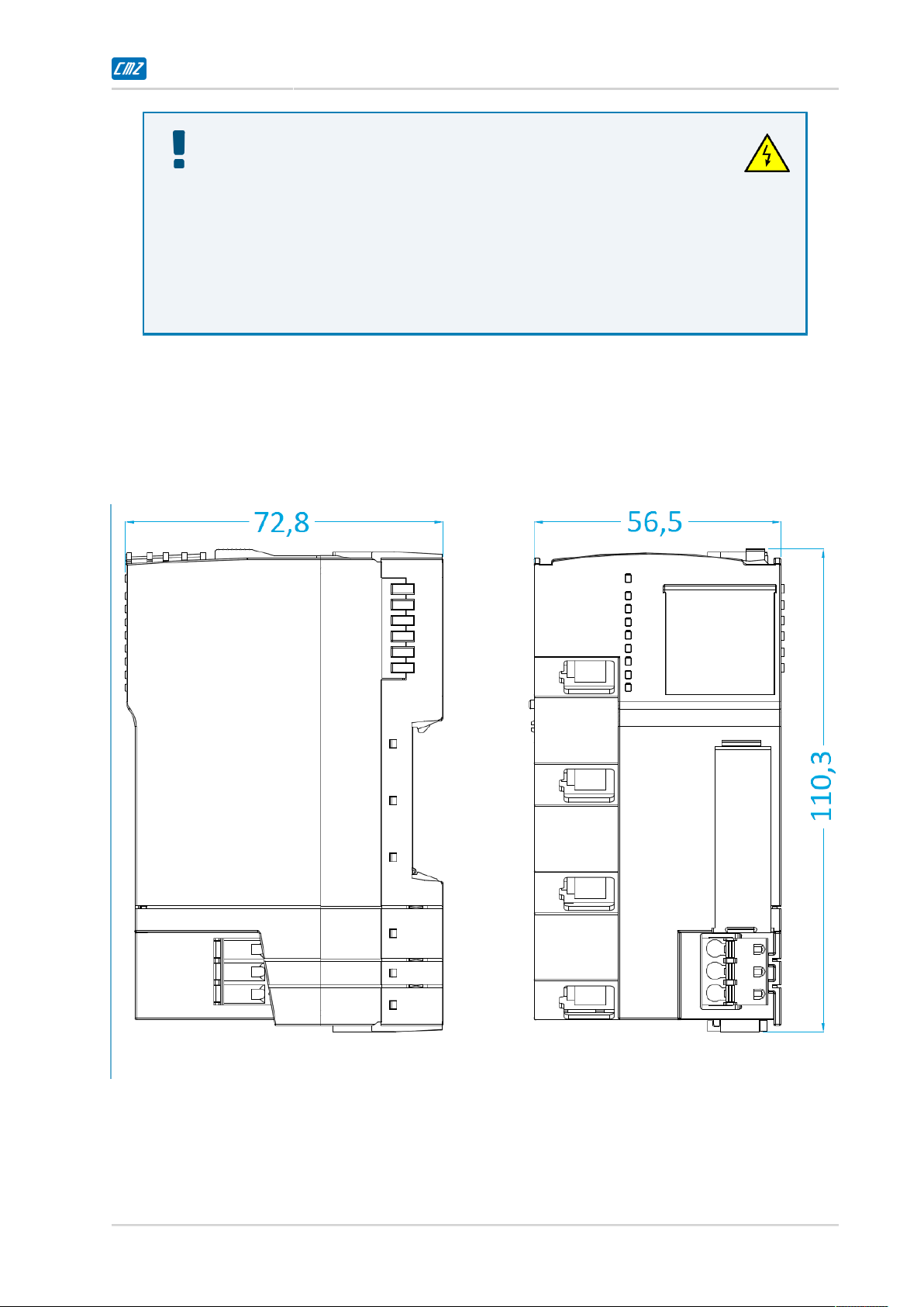
3.Dimensions and sizes
Lateral right and frontal views of the FCT640.
Figure1.FCT640 dimensions [mm].
•The DIN rail must be "top hat" type according to the EN 60715, with height 35 mm,
thickness 1 mm, not subject to corrosion and with clean and conductive surface;
•Indicative weight: about 230 g.
Doc. TR301901 - Ed. 1.2 - 29 Sep 2021 3
FCT640 www.cmz.it
Warning
The DIN rail connects to the system functional earth: connect it to the panel ground.
4.Installation and disassembling
In order to optimize the thermal dissipation the controller must be installed in vertical position
(with X1 as lower connector), with DIN rail horizontal. The DIN rail must be firmly xed to
the internal back of the electrical panel.
The FCT640 system installation must provide the dissipation of the heat that is generated by the
system itself through the upper/lower air vents, by guaranteeing a sufficient free volume inside
the panel in which it is installed. In fact the system produces heat that must be dissipated inside
the panel and for this reason it is absolutely necessary to guarantee a minimum air convection
from the other devices.
The FCT640 and eventual additional modules must be installed leaving free at least 10 cm on
the top and bottom sides and 5 cm on the lateral sides, and avoiding hot zones in the panel as
drives or motor braking resistors and the zones with EMC interferences.
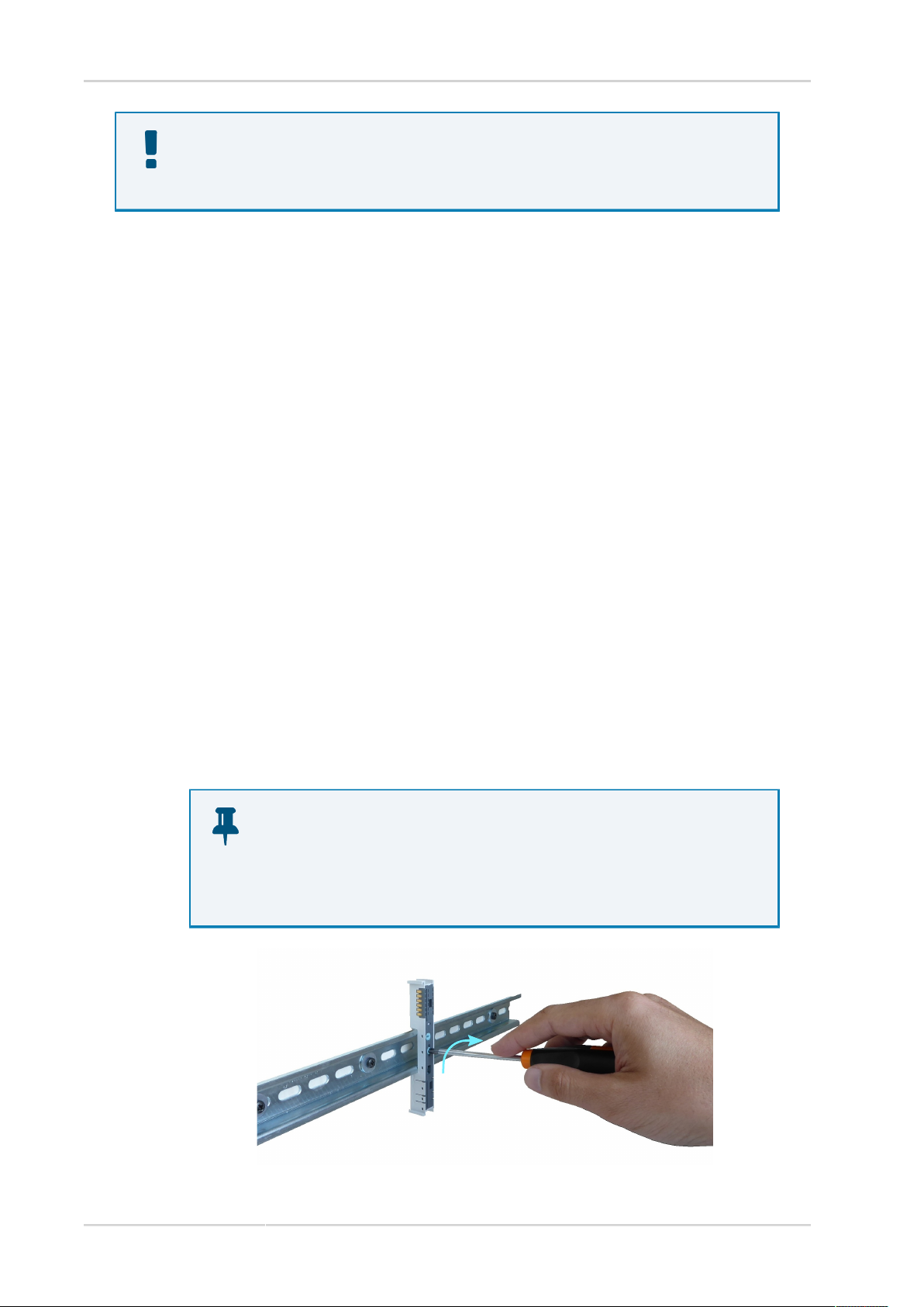
Assembling
1. In case the backplane connector is separated, x the base for the modules on the DIN
rail by making a quarter of clockwise revolution (90°) on the star-shaped insert on the
module center.
Important
Do not force the modules insertion on the backplane connector: previous-
ly check that the orientation of the coding insert is compatible with the orienta-
tion of the insert on the FCT640 back.
90°
4Doc. TR301901 - Ed. 1.2 - 29 Sep 2021
Short Guide
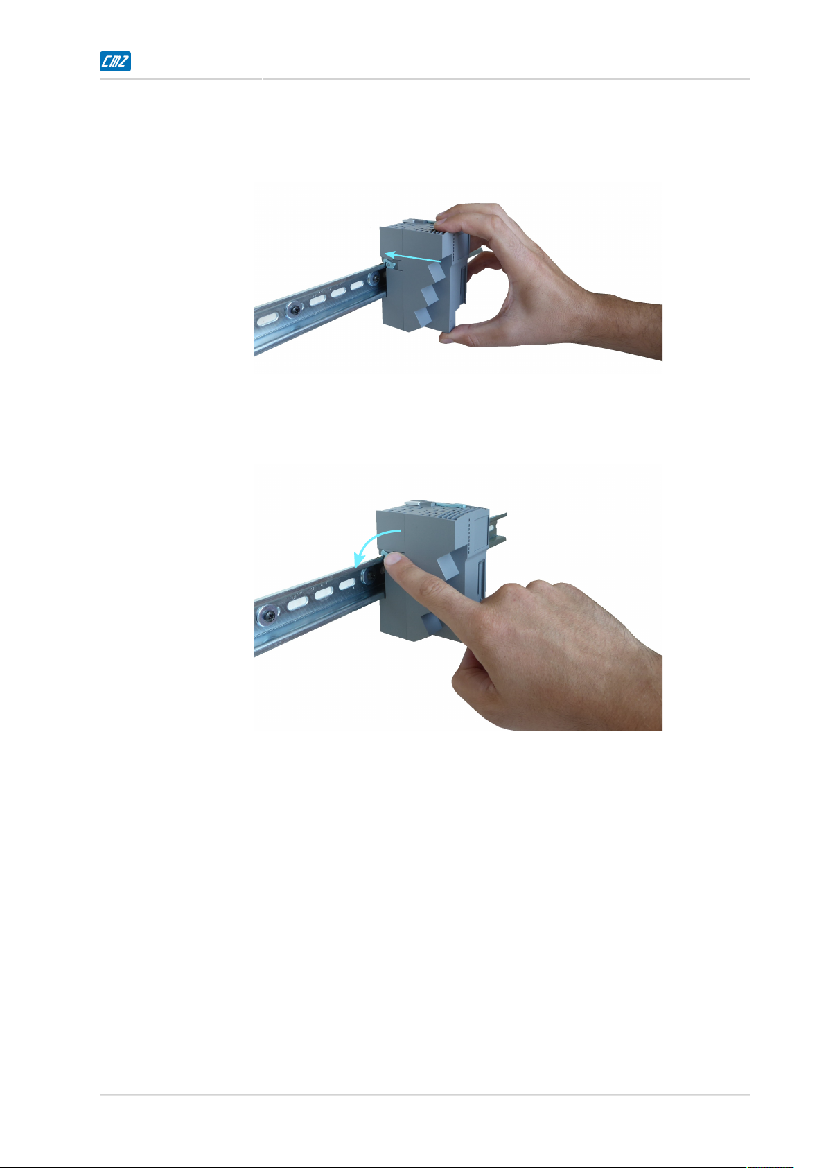
2. Insert the device in the backplane connector, by sliding it perpendicularly to the DIN
rail. Push it towards the backplane connector until the blocking device springs (until
a slight "click" can be heard).
3. Rotate couterclockwise the blocking lever on the left of the device in order to x its
position on the DIN rail.
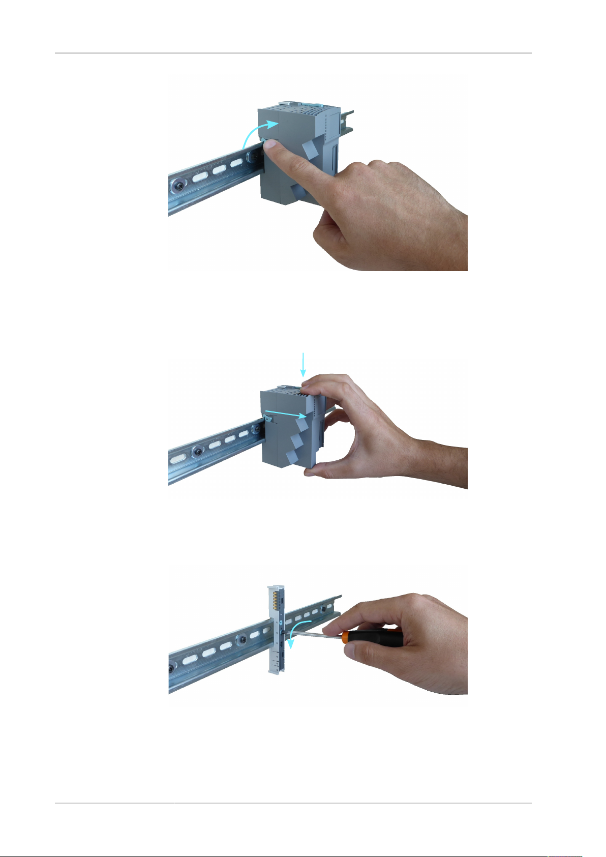
Disassembling
1. Rotate clockwise the blocking lever on the left of the device in order to free its position
on the DIN rail.
Doc. TR301901 - Ed. 1.2 - 29 Sep 2021 5
FCT640 www.cmz.it
2. While pushing the lever, pull the device perpendicularly to the DIN rail. In this way
the backplane connector will remain anchored to the DIN rail: this allows a faster sub-
stitution of the controller.
3. Remove the base for the modules from the DIN rail by making a quarter of revolution
(90°) counterclockwise, on the appropriate star-shaped insert on the module center.
90°
6Doc. TR301901 - Ed. 1.2 - 29 Sep 2021
Short Guide
5.Electrical connections
Required instruments, materials and equipment
For the correct functioning of the controller, protection included, the installation of the follow-
ing components is required:
•Fuse (slow-blow fuse, max. 8A) to be installed in series to the following pins of X1: L+
and AUX (only if used). It must protect the internal electronics of the FCT640 in case
of shirt-circuit or overload.
•24 VDC power supply to be connected to the L+ (+) and GND (-) signals of X1. The
power supply must have a stabilized output voltage and output current adequate to the
absorption of the FCT640 and of the connected modules (in case the AUX signal is used,
it is necessary that a compatible source is connected to the AUX (+), GND (-) signals
of X1).
Caution
The FCT640 is not internally protected against the overload or short-circuit on the supply sec-
tion. Protect the product with fuses that complies with the technical data and the local regu-
lations.
5.1.Precautions during the wiring
Before to supply the FCT640, the DIN rail must be wired to the panel earth for EMC compati-
bility: through it the spring contacts connect the controller to the earth.
Caution
Do not exceed the 8A limit on each pin of the connector X1. In case of higher absorp-
tion use the proper supply modules TB20.
Important
The correct functioning of the FCT640 needs the earth-
ing of the DIN rail is made through a reliable contact of the DIN rail posteri-
or springs. Avoid any mechanical strain on the controller in order to not risk to inter-
rupt the electrical connection.
The wiring of the connector X1 must respect the SELV/PELV requirements and the SELV/
PELV circuits segregation and insulation requirements in relation to the different kind of cir-
Doc. TR301901 - Ed. 1.2 - 29 Sep 2021 7

FCT640 www.cmz.it
cuits. Furthermore the wiring must be made with wires that are appropriate to the application,
according to the temperature and insulation voltage of the other circuits with higher voltage.
•Do not use power suppliers with characteristics that are different from the indicated
ones.
•Do not connect more power suppliers in series and/or parallel in order to avoid to exceed
the limitations of the certified voltage/current rating.
•Do not reverse the supply polarity.
•Do not connect the power supply to the FCT640 without the protection of the fuses
that are indicated in Required instruments, materials and equipment.
6.Peripherals connection
For the connection of the peripherals (modules) to the controller, refer to the "TB20 – Digital,
Analog, and System Modules" manual, that can be downloaded from the CMZ website: http://
www.cmz.it.
7.CE compliance
The FCT640 controller respects the following European directives:
•2014/30/UE relating to electromagnetic compatibility;
•2006/66/EC on batteries and accumulators and waste batteries and accumulators.
in conditions in which the instructions in the user documentation are respected and there are
not particular work environment or installation needs.
CMZ SISTEMI ELETTRONICI S.r.l. guarantees the conformity of the controller to the fol-
lowing harmonized standards:
EN 61131-2:2007 Programmable controllers - Part 2: Equipment requirements and tests
The system integrator has the responsibility to guarantee that the product or the final system
comply to the pertinent regulations that are in force in the country in which the product (or the
entire system) is used.
Danger
The machine user that uses the FCT640 controller must execute a risk analysis of the ma-
chine and must implement proper actions in order to ensure that any unexpect-
ed event may cause damage to any person or to the machine.
8Doc. TR301901 - Ed. 1.2 - 29 Sep 2021

Short Guide
8.Technical features
Main supply section
Rated voltage 24 VDC (-15% / +20%)
Internal protections Polarity reversal
Absorbed current @ 24 VDC 350 mA (continuous, no modules connected)
550 mA (peak, no modules connected)
Table1.FCT640 electrical features.
Other data
Supply protection Undervoltage < 17 VDC
Surrounding air temperature 0 ÷ +40 °C
Storage ambient temperature -20 ÷ +50 °C (for long storage time)
-20 ÷ +70 °C (for short storage time)
Relative humidity of storage and
operation (without condensation) +5 ÷ +95 %
Weight About 230 g
Maximum altitude 4000 m [s.l.m.]
Ventilation Natural convection
Pollution degree 2
Protection degree IP20
EMC zone B (general industrial environment)
3xRJ45 Ethernet 10/100 Mb/s (X2,
X3, X4 with X2 default for De-
bug/PC/CODESYS/HMI)
Communication ports
1xRJ45 CAN bus (X5)
Fieldbus EtherCAT Master (X2, X3, X4), CANopen Master (X5)
Processor RISC, dual-core 1.0 GHz 64 bit, 3 level cache
Volatile memory DRAM 512 MB DDR3L-1600
Retentive memory for application MRAM 32 KB
Mass storage Flash NAND 1GB
Retentive memory extension SD Card
Clock Internal RTC with backup through battery CR2032 (included)
Operative system real-time
Programmability CODESYS, CMZ libraries
Language IEC 61131-3
Modularity extensible up to 64 local modules
Status report 9 leds
Buttons reset, recovery
Table2.Generic features
Doc. TR301901 - Ed. 1.2 - 29 Sep 2021 9

FCT640 www.cmz.it
9.Connectors
RESET
RECOVERY
SDCARD
X1 24V
X2 ETH0
X3 ETH1
X4 ETH2
X5 CAN
BUS-TERM OK/BF
FAULT
LINK 2
LINK 1
LINK 0
-
-
(Switch)
SF
SD
DC
Figure2.Connectors arrangement.
X1 Control
supply (remov-
able connector)
Metz SP06603VBNC
Connector type - female extractable
Poles number - 3
Stranded copper conductor section [mm2] 0,8 ÷ 2,5
Rated voltage [VDC] 24
Rated current [A] 8
10 Doc. TR301901 - Ed. 1.2 - 29 Sep 2021

Short Guide
PIN Signal Description
1 AUX Terminal for the additional voltage potential 0 ÷ 24 VD-
C(ref. to GND)
2 GND Ground Control Supply
3 +24 V_DC +24 VDC Control Supply
ELITALIA MJ99-88AB
Connector type - RJ45 femalea
Poles number - 8
Network interface - 10/100 BASE-T
Bit rate - 10/100 Mb/s
Autonegotiation - Yes, with HP Au-
to-MDIX technology
Cable - CAT-5 S/FTPb(or better)
Characteristic impedance Z0[Ω] 100
Maximum cable length [m] 100
X2, X3, X4 Eth-
ernet
PIN Signal Description
1 TD+ Transmit data +
2 TD- Transmit data -
3 RD+ Receive data +
4 - Not connected
5 - Not connected
6 RD- Receive data -
7 - Not connected
8 - Not connected
ELITALIA MJ99-88AB
Connector type - RJ45 femalea
Poles number - 8
Network interface - CAN (ISO-11898
v2.0 Part B)
Communication protocol - CANopen DS301
Baud rate kbaud/s 50/125/250/
500/800/1000
Termination resistor [Ω]
120 (see Switch for the
CANopen termination
resistor (BUS-TERM))
Cable - CAT-5 S/FTPb (o better)
Characteristic impedance Z0[Ω] 120 (100 Ω ≤ Z0 ≤ 150 Ω)
X5 CANopen
PIN Signal Description
1 CAN_H CAN high
2 CAN_L CAN low
3 CAN_GND CAN ground
Doc. TR301901 - Ed. 1.2 - 29 Sep 2021 11

FCT640 www.cmz.it
PIN Signal Description
4 ÷ 9 - Not connected
aTo guarantee a higher reliability of the connection, it is suggested to use a connector with a shield-clamping collar.
bThe S/FTP cable is provided with shielding of the single twisted pairs in aluminium foil and copper clad braid screen.
9.1.SD Card slot
The FCT640 system includes an external interface for SD Card memory boards accessible by
lifting up the frontal transparent window. The SD Card port allows different functionalities
including the mass data storage and the automatic update of the system software.
The port is protected against overload and short-circuit of the SD card through the electronic
current limit with signal report on the fault led.
In the Table 3 the main characteristics of the SD card, that can be used with the system, are
reported.
Insert the card up to the 'click'.
To remove the card it is sufficient to push and release it (push-pull slot).
Important
After the use of the SD card it is recommended to remove it and close the frontal transpar-
ent window: that is useful to avoid the entrance of humidity, dust, and extraneous particles in-
side the device. Always close the SD card slot when it is not inserted.
Supply voltage [VDC] 3,3
Overload protection thershold [mA] 400
Standard - SD Card Specification Ver.2.0
Table3.SD Card characteristics.
Important
CMZ recommends to use the S-250 series of Swissbit SD cards, after having tested their com-
patibility with the controller and by recognizing a performance that is suitable with in-
dustry about temperature range and data retention reliability (SLC technology). The avail-
able sizes are 512 MB, 1 GB and 2 GB and it is possible to purchase the 1 GB version direct-
ly from CMZ.
10.Leds
For the leds disposal see Figure 2.
12 Doc. TR301901 - Ed. 1.2 - 29 Sep 2021

Short Guide
The leds, placed on the upper-front side of the FCT640, may assume the following states:
•OFF: led switched o;
•ON: led switched on;
•BLK (blinking): led 500 ms on, 500 ms o;
The notifications meaning of the leds (in top-down order) can be found in the following table:
Leds Colour Status Meaning
- OFF Not supplied system
ON System ready, configuration complete
BLU BLK System in start-up or unable to pass to the operative cycle due to
a wrong configuration of the modules (missing, wrong, ...)
OK/BF
RED ON At least one module is in error and provides a diagnostic report
message (for example "wire break")
- OFF No system error (or backplane bus error)
ON The instelled plug-in module model is wrong or it is not CMZ
SISTEMI ELETTRONICI S.r.l.
SF YELLOW
BLK Module missing (at the start-up) / module removed (during the
operation)
- OFF System correctly started without alarms
ORANGE ON System in Debugger mode
ON System software update in progress
2 BLK Internal RTC Clock not set or its backup battery has ran out
FAULT
RED
3 BLK HW initialization error (Ethernet or other resources)
- OFF SDCard not inserted
RED BLK The system is accessing the memory card in reading or writingSD
ORANGE BLK Current overload of the memory card. Remove the device.
- OFF Communication not active on ETH2 port
LINK 2 GREEN BLK Communication active on ETH2 port
- OFF Communication not active on ETH1 port
LINK 1 GREEN BLK Communication active on ETH1 port
- OFF Communication not active on ETH0 port
LINK 0 GREEN BLK Communication active on ETH0 port
- - OFF Not used
- - OFF Not used
Table4.Description of the leds for FCT640 controller.
11.Buttons and switch
For the arrangement of the buttons and the switch refer to Figure 2.
Doc. TR301901 - Ed. 1.2 - 29 Sep 2021 13

FCT640 www.cmz.it
Button 1 (RESET)
This button, that can be pushed through a pointed tool (diameter < 0,8 mm), allows to force a
controller reset procedure.
Push the button and release it. Wait until the third led "FAULT" remains steady ON.
Caution
If it is pushed during the functioning it interrupts every procedure/activi-
ty of the FCT640 and of the local modules connected to it. Be sure that the reset re-
quest does not imply a risk for the safety of any person or for the damage of the ma-
chine or for the loss of data.
Button 2 (RECOVERY)
This button is used to delete the application (File System format: application, parameters, user
les, ...), while the rmware and the licenses are not deleted.
The "RECOVERY" sequence, which is reported here below, is intentionally laborious in order
to avoid that the application is deleted by mistake or without intention.
1. execute a reset through the Button 1 (RESET) waiting that the third led "FAULT" re-
mains steady ON;
2. hold the Button 2 (RECOVERY) pushed until all the leds turn on, then release the
button;
3. push the Button 2 (RECOVERY) three times, at a distance of 2 seconds from each other
(in this phase the lowest led corresponds to the button status: it turns-on when the
button is pushed. Wait its turn-on before to release the button);
4. Push the Button 2 (RECOVERY) the fourth time and hold it until all the leds are on,
then release the button;
5. after about 10 seconds the application is deleted. The leds blink more and more faster,
to indicate the approaching of the deletion. The procedure can be interrupted before
the time elapses, by cutting out the system supply (turning it o);
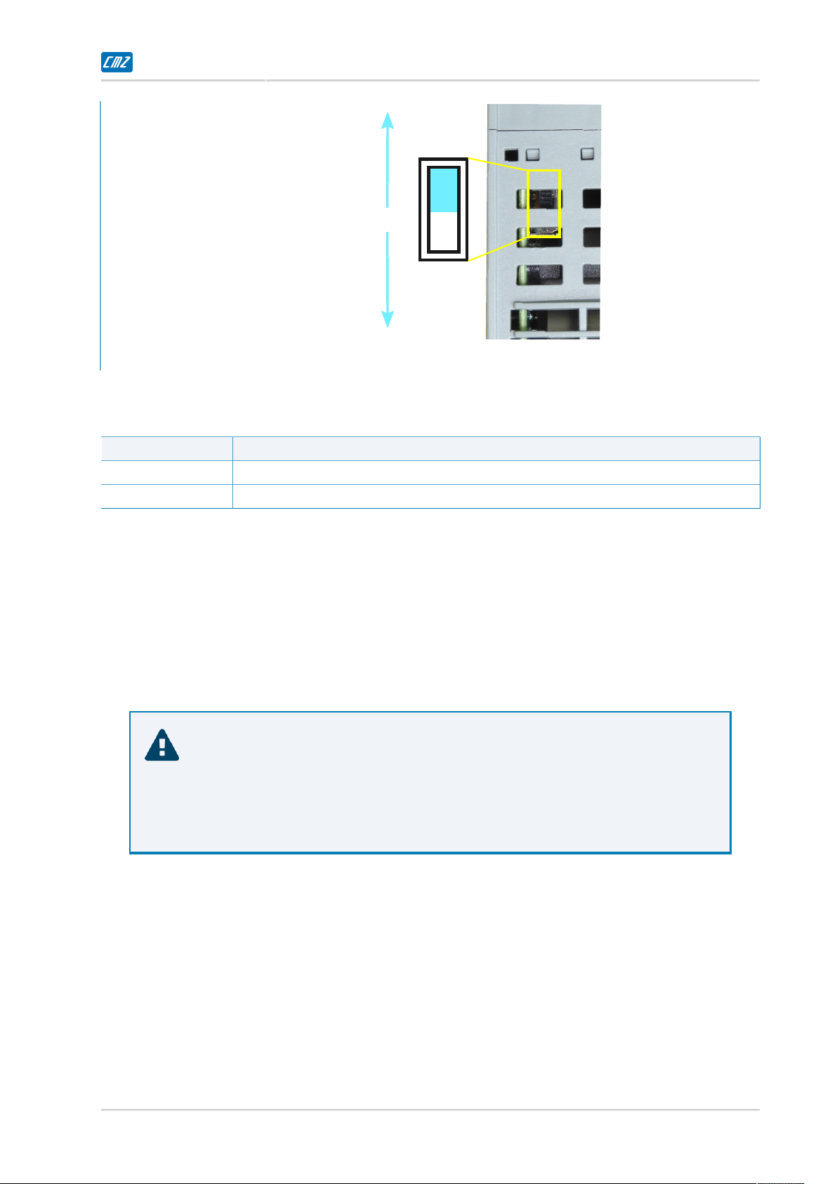
Switch for the CANopen termination resistor (BUS-TERM)
This controller contains a termination resistor for the CANopen network that can be inserted
or not, according to the need. Its configuration (reported by the written "ON" and "OFF" on the
left side of the controller, in correspondence with the switch itself) is described in the Table 5.
14 Doc. TR301901 - Ed. 1.2 - 29 Sep 2021
Short Guide
Termination
inserted
(ON)
Termination
not inserted
(OFF)
Figure3.CANopen termination resistor switch
Position Resistor status
OFF Termination resistor not inserted
ON Termination resistor inserted (DEFAULT)
Table5.Setting of the switch (BUS-TERM).
The modification of the BUS-TERM switch position is necessary only if the FCT640 is not the
final node of the CAN network: the operation must be carefully executed by an expert operator
after the controller has been disconnected from any other device, power supply and additional
modules included; then it is necessary to move the switch by inserting a at-blade screwdriver 0.5
x 3 mm in the air vent indicated in Figure 3.
Caution
Modify the BUS-TERM switch position only after the FCT640 complete disconnec-
tion from any power source and the turning o of all the leds. Exclusively use the indicated ob-
ject through the dedicated air vent. In all the other cases DO NOT introduce any object in or-
der to avoid internal damages!
12.Battery
The FCT640 is provided with a system clock supplied by a backup battery that allows the main-
tenance of the related data in case of 24 VDC supply missing. The battery is already installed and
working inside the system. In case of internal clock setting loss after the turn-o of the system,
and in any case after 10 years, it will be necessary to replace the internal battery.
For its substitution exclusively use a battery which characteristics are below reported: after it, the
setting of the system date/hour will be necessary.
Doc. TR301901 - Ed. 1.2 - 29 Sep 2021 15

FCT640 www.cmz.it
Caution
The FCT640 controller chassis can be opened only in order to substitute the internal bat-
tery: this operation is delicate and must be executed by an expert operator according to pre-
cise instructions that can be requested to the system supplier . Pay attention to the substitu-
tion operations and to the correct polarity of the battery during its substitution since the sys-
tem contains components that are sensitive to ESD disturbance and it is not protect-
ed against the polarity reverse of the battery.
The battery characteristics are the following:
Characteristic Value
Type CR 2032 (e.g. VARTA mod. 6032 101 501)a
Material Lithium, not rechargeable, (LiMn204, Lithium content 0,07 g)
Rated voltage 3,0 V
Capacity 200 mAh min.
Absorption 1µA max.
Service life 10 years
Absorption 1 µA max.
aPay attention to the compatibility with the application temperature range.
Table6.Backup battery features.
13.First system switch-on
The following components must be available in order to execute the rst switch-on of the system:
•FCT640 and material indicated in Required instruments, materials and equipment;
•PC with Ethernet port; required applications: FCTTool (from CMZ website) and
CODESYS 3.5 or higher;
•Ethernet cable RJ45-RJ45 cat. 5 S/FTP.
1. Install the FCT640 according to the requirements indicated in Installation and disas-
sembling and Electrical connections;
2. Connect point-to-point the Ethernet cable between the PC and the connector X2 of
the FCT640; take note of the MAC address related to the connector, as reported on
the FCT640;
3. Supply the FCT640;
4. Identify the MAC address previously obtained through FCTTool: then configure the
identification parameters of the network in which the FCT640 has to be used; if this
step is not fulfilled at the FCT640 network settings, default values are assigned;
16 Doc. TR301901 - Ed. 1.2 - 29 Sep 2021
Short Guide
5. Connect the FCT640 to the configured network and reboot it.
Important
This section is dedicated to the rst installation and is not complete with all the opera-
tions that are necessary for the product use. For specific details refer to the FCT640 com-
plete manual.
14.Methods of product disposal at the end of life
The device must be disposed as electrical or electronic waste. The packaging of the product is of
good quality and can be re-used. For the recycling or the disposal of a product or of a packaging,
CMZ exhort to respect the current regulations and the more appropriate procedures.
Caution
In order to avoid explosions and damages to things or people, it is recommend-
ed to not recharge or short-circuit the battery, not expose it to heat source, not put it under me-
chanical strain.
Important
Before to dispose the product it is recommended to remove the internal battery and dis-
pose it separately according to the local regulations.
15.Safety precautions
Warning
Before to perform any operation on the product, remove the voltage supply and en-
sure that there are no risks related to the disconnection from the power source of all the con-
nected devices which functioning depend on the FCT640.
Important
Avoid long periods of storage that may imply the damage of the system due to the pos-
sible leak of corrosive substances from the battery and its discharge. In or-
der to avoid it, in case the product remains unused for a of long period, it is recommend-
ed to physically remove the internal battery: for the instructions about this operative proce-
dure contact the supplier of the system.
Doc. TR301901 - Ed. 1.2 - 29 Sep 2021 17
FCT640 www.cmz.it
Important
The FCT640 controller must not be opened or disassembled by the user. The open-
ing of the plastic cover of the FCT640 is allowed only in case of the substitu-
tion of the battery and must be made by an expert operator according to precise instruc-
tions that can be requested to the supplier support. For all the other maintenance oper-
ations contact the CMZ Technical Support (references at the end of the present docu-
ment). In case of alteration of the controller the warranty is void.
Caution
CMZ SISTEMI ELETTRONICI S.r.l. reserves the right to make modifications to the prod-
ucts that are described in this document at any time and without notice.
This document was written by CMZ SISTEMI ELETTRONICI S.r.l. on-
ly to be used by its customers, providing the most updated version related to the prod-
ucts at the date of publishing.
It's intended that the documentation use by the user is under its own respon-
sibility and that the use of certain functions that are described in this docu-
ment must be made with the due care, so that to avoid danger for the person-
nel and dameges to the machines.
No other warranty is provided by CMZ SISTEMI ELETTRONICI S.r.l., in particu-
lar for possible imperfections, incompleteness, and/or any other difficulties.
This document contains confidential informations that are proper-
ty of CMZ SISTEMI ELETTRONICI S.r.l.. Neither the document nor the contained in-
formation can be disclosed, in whole or in part, without the prior written permis-
sion of CMZ SISTEMI ELETTRONICI S.r.l..
For support please contact:
CMZ SISTEMI ELETTRONICI S.r.l.
Via dell'Artigianato 21, Carbonera, TV, Italy
telefono: +39 0422 447411
email: [email protected]
sito web: http://www.cmz.it
18 Doc. TR301901 - Ed. 1.2 - 29 Sep 2021
Table of contents


