Rheem THERMAL IQ LINK DPi1 User manual

rheemthermal.com.au
DESCRIPTION
The Rheem IQ®Link DPi1 controller is suitable for connection where a separate pump
is installed on a heating circuit in combination with a Rheem Thermal heat pump.
OPERATION
The DPi1 controller is designed to switch a 240V pump, rated to 9.98 Amps, 2395 watts
controlled from the ‘HEATER INTERLOCK’ output of a Rheem Thermal heat pump.
DEMAND HEAT
Your Rheem Thermal heat pump includes Rheem IQ®which provides a range of
advanced control functions to aid operation and service. This includes a ‘CYCLE TO TEST
TEMPERATURE’ function that will assist in maintaining the temperature of the pool or spa
by communicating to the DPi1. The DPi1 will start the circulator pump when heating is
called for by the Rheem IQ®controller, which monitors the pool or spa temperature.
PROGRAMMING DEMAND HEAT
To program and switch on the demand heat function in the Rheem Thermal heat pump
controller, refer to the back page of these instructions.
RHEEM THERMAL
RHEEM IQ® LINK
DPi1
DIGITAL PUMP
INTERFACE

rheemthermal.com.au
INSTALLATION INSTRUCTIONS
CONTROLLER MOUNTING
Find a suitable location to mount the control box. Ideally, as with all pool equipment,
it should be installed out of direct weather and no closer than 3 metres from the water’s
edge and a minimum 600mm above ground. The power cable is 1.8m long and should
be plugged directly into a general power outlet, not into an extension lead.
PUMP CONNECTION
The circulation pump plugs into the 3 pin, 240V socket beneath the
DPi1 controller marked ‘PUMP CONNECTION’.
HEATER INTERLOCK
Plug in the ‘HEATER INTERLOCK’ lead from the DPi1 controller to the female socket
on the side of the Rheem Thermal heat pump marked, “Rheem IQ®DPi Link”.
Note: Damage caused by incorrect connections will void warranties.
Fix the mounting bracket to a solid structure via screws and wall plugs kit provided,
and slide the controller on, locking into place. Adjusting screws on the back of unit
to ensure snug fit. To remove unit, lift and gently pull away from structure.
Rheem Thermal
Heat Pump
Flow
Flow
Heater
Interlock
Pool / Spa
PLUG INTO
240V GPO
RHEEM IQ®
LINK DPi1
DIGITAL PUMP
INTERFACE
P/N: 26843
WARRANTY
This range of product is covered by a limited 2 year warranty against component failure or
faulty workmanship from the date of installation. A faulty unit should be returned in the first
instance to Rheem Thermal or the Rheem Thermal dealer from which the unit was purchased.
Damage to the unit due to misuse, power surges, lightning strikes or installation that is not in
accordance with the manufacturer’s instruction may void the warranty.
Warranty does not cover postage or travel costs to or from installation site.
If the power cord is damaged, do not use the controller; return the unit to Rheem Thermal
or the Rheem Thermal dealer from which the unit was purchased for repair.
Customer Record. (To be retained by the customer)
Dealer/Installer Name:
Serial Number:
Date Installed :
RHEEM IQ® LINK DPi1
DIGITAL PUMP INTERFACE

rheemthermal.com.au
INSTRUCTION SHEET FOR
PROGRAMMING ‘DEMAND HEAT’
Programming Demand Heat on your RHEEM THERMAL HEAT PUMP CONTROLLER
The Rheem Thermal heat pump comes with an advanced Rheem IQ®control that is designed to
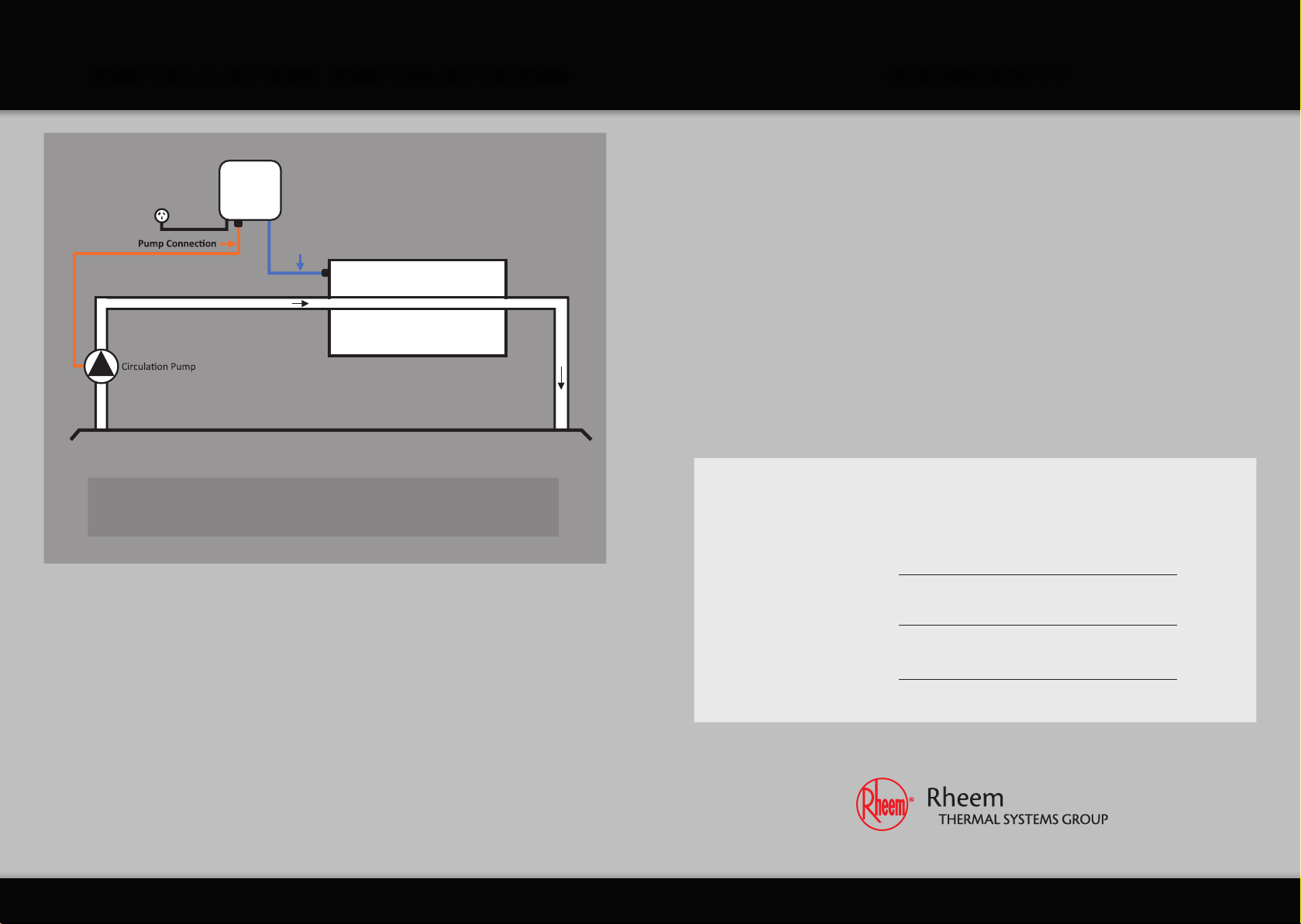
communicate with your Rheem IQ®- Link DPi Digital Pump Interface control.
The ‘Cycle to Test Temperature’ setting in Rheem IQ®is designed to control operation of the
system water pump(s). With this function activated, Rheem IQ®will turn the water pump ‘ON’ so
that the heat pump can check the current pool or spa water temperature. If heating is required,
the water pump remains ‘ON’ until the pool or spa has reached temperature and the pump is
switched ‘OFF’. The heat pump will ‘Cycle to Test Temperature’ throughout the day determined
by the time setting programmed by the owner.
To activate the Demand Heat function, ‘Cycle to Test Temperature’ needs to be set to ‘ON’
and ‘Enable Unit on/off by Flow Switch’ needs to be set to ‘No’.
Adjust the set points at the Rheem IQ®controller screen on your heat pump as follows:
1. Whilst in the home screen, press and release . The screen will change to the ‘Main menu’.
2. Press and release or until ‘A. On/Off Unit’ is selected.
3. Press and release . The screen will change to show ‘ON’ or ‘OFF’.
4. Press and release or . The screen will change to show ‘Type of circulating pump
control’ and the current setting.
5. Press and release . The first letter in the current setting will start flashing.
6. Press and release or until the desired setting is displayed.
7. Press and release to confirm the selection. With ‘CYCLE TO TEST TEMP’ selected,
proceed to step 8.
8. The first digit in the ‘temp test cycle’ time will now be flashing. Press and release or
until the desired time setting is displayed. The time setting can be changed in 0.5 hour
increment from 0.5 to 5.0 hours.
9. Press and release to confirm the time selection. The first digit in the ‘temp test cycle’ time
will stop flashing and the setting will be saved.
10. Press and release twice to go back to the home screen.
11. Whilst in the home screen, press and release or to change to the ‘Main menu’ screen.
12. Press and release or until ‘G. Service’ is selected.

rheemthermal.com.au
INSTRUCTION SHEET FOR
PROGRAMMING ‘DEMAND HEAT’
13. Press and release .
14. Press and release or until ‘F. Service’ is selected.
15. Press and release . and enter the four digit password ‘0022’ (Set first digit then press
to move to the next digit etc.). When the last digit has been set press and release.
Note: This step will not occur if the password has been previously entered within 10 minutes.
16. Press and release or until ‘C. Thermoregulation’ is selected.
17. Press and release .
18. Press and release or until ‘C. Thermoregulation 06’ is selected.
19. ‘Enable Unit On / Off ‘ screen will be displayed.
20. Press and release to move cursor to ‘Yes’ on the right of ‘By Flow Switch’.
Should be flashing.
21. Press and release or to select ‘No’ as appropriate.
22. Press and release .
23. Press and release or four times to go back to the home menu.
24. Press and hold or for 2 seconds to clear all active alarms.
The Rheem Thermal heat pump is now programmed and ready to use with the
Rheem IQ®- Link DPi Digital Pump Interface Controller.
The ‘Cycle to Test Temperature’ function should be set at the time of installation by the
installer and does not normally require changing.
Controller set up is completed.
Australian
Standard
AS/NZS 2712
Lic SMK 0757
Lic SMK 1048
Lic SMKP 21548
SAI Global
AS 3498
Lic WMKA 00153
Lic WMKA 00177
Lic WMKA 00299
Lic WMKA 00500
Lic WMKA 21434
Lic WMKA 21549
Lic WMKA 21766
SAI Global
Quality
ISO 9001
TM
Materials and data subject to change without notice due to ongoing product
improvements. Rheem Thermal is a division of Rheem Australia Pty Ltd.
HEAD OFFICE
Rheem Thermal Systems Group
43 Marigold Street, Revesby NSW 2212
PO Box 146 Moorebank NSW 1875 Australia
Sales: 1300 132 950
Service: 02 9684 3684
Intl: +61 2 9684 3684
Fax: (02) 9684 3698
Email: sales@rheemthermal.com.au
Web: www.rheemthermal.com.au
ABN: 21 098 823 511

rheemthermal.com.au
Materials and data subject to change without notice due to ongoing product
improvements. Rheem Thermal is a division of Rheem Australia Pty Ltd.
HEAD OFFICE
Rheem Thermal Systems Group
43 Marigold Street, Revesby NSW 2212
PO Box 146 Moorebank NSW 1875 Australia
Sales: 1300 132 950
Service: 02 9684 3684
Intl: +61 2 9684 3684
Fax: (02) 9684 3698
Email: sales@rheemthermal.com.au
Web: www.rheemthermal.com.au
ABN: 21 098 823 511
Australian
Standard
AS/NZS 2712
Lic SMK 0757
Lic SMK 1048
Lic SMKP 21548
SAI Global
AS 3498
Lic WMKA 00153
Lic WMKA 00177
Lic WMKA 00299
Lic WMKA 00500
Lic WMKA 21434
Lic WMKA 21549
Lic WMKA 21766
SAI Global
Quality
ISO 9001
TM
Table of contents
Other Rheem Controllers manuals
Popular Controllers manuals by other brands

Compur Monitors
Compur Monitors Statox 501 Operation instructions

TIME LED
TIME LED 781296 Installation and operating instructions

Lynxspring
Lynxspring JENEsys Edge 414 installation guide

IFM
IFM CR7132 Original operating instructions

Sunricher
Sunricher SR-2850C manual

Ruida Technology
Ruida Technology LFS-PM-T43 operating manual