CNC UC400ETH User manual

1
Stefan Gemeinert,Frühlingstrasse 8 85253 Erdweg
Tel: 081386695536 www cnc-technics de
Breakoutboard für
UC400ETH
Operation Manual
All rights to these operating instructions remain with cnc-technics Texts, information and
illustrations of these operating instructions may not be reproduced, distributed or used for
purposes of competition without authorization or communicated to others

2
Stefan Gemeinert,Frühlingstrasse 8 85253 Erdweg
Tel: 081386695536 www cnc-technics de
Table of Contents
Introduction ................................................................................................................................ 3
Delivery Parts............................................................................................................................. 3
Description ................................................................................................................................. 4
Commissioning........................................................................................................................... 5
Inputs.......................................................................................................................................... 6
Outputs ....................................................................................................................................... 8
Adjust the Axes ........................................................................................................................ 10
Adjust the Spindle .................................................................................................................... 12
Spindle direction.................................................................................................................. 13
Relay outputs............................................................................................................................ 16
Status Display........................................................................................................................... 17
Charge Pump ............................................................................................................................ 18

3
Stefan Gemeinert,Frühlingstrasse 8 85253 Erdweg
Tel: 081386695536 www cnc-technics de
Introduction
This manual contains instructions for mounting, using the breakout board
It is imperative to connect 230V connections by a knowledgeable
electrician.
These operating instructions have been prepared with care If you still find
errors, we would be grateful for an indication
Delifery
•Current version of the manual
•Breakoutboard

4
Stefan Gemeinert,Frühlingstrasse 8 85253 Erdweg
Tel: 081386695536 www cnc-technics de
Description of the breakout board
The breakout board enables the operation of up to 4 stepper motor or servo
output stages on the UC400Eth
For this the control Software Mach3 / UCCNC (not included) is used The board
has various inputs and outputs that can be individually set as many different
configurations are possible Depending on the selected configuration,
additional functions are available, such as control of a frequency converter via
an analog signal of 0-10V or 0-5V, reference switch, spindle direction relay, up
to 3 relay outputs and one Charge Pump
All signals are protected by Optocouplers All machine-side signals are rated
from 5V to 30V, ensuring robustness and compatibility even with industrial
sensors (PNP SENSORS)

5
Stefan Gemeinert,Frühlingstrasse 8 85253 Erdweg
Tel: 081386695536 www cnc-technics de
Commissioning
Installation of the UC400ETH
The UC400ETH is screwed onto the 4 spacer bolts with M3 screws
The operating voltage is supplied via the Breakoutboard

6
Stefan Gemeinert,Frühlingstrasse 8 85253 Erdweg
Tel: 081386695536 www cnc-technics de
Inputs
Each input port is provided with its Pin number
in Mach3/UCCNC at Ports & Pins has to put a hook in Active Low
When the limit switch is actuated, it internally switches to ground and Mach3 detects a
response at the input PNP sensors switch with the switching voltage so they are also direct
connected

7
Stefan Gemeinert,Frühlingstrasse 8 85253 Erdweg
Tel: 081386695536 www cnc-technics de
8
Stefan Gemeinert,Frühlingstrasse 8 85253 Erdweg
Tel: 081386695536 www cnc-technics de
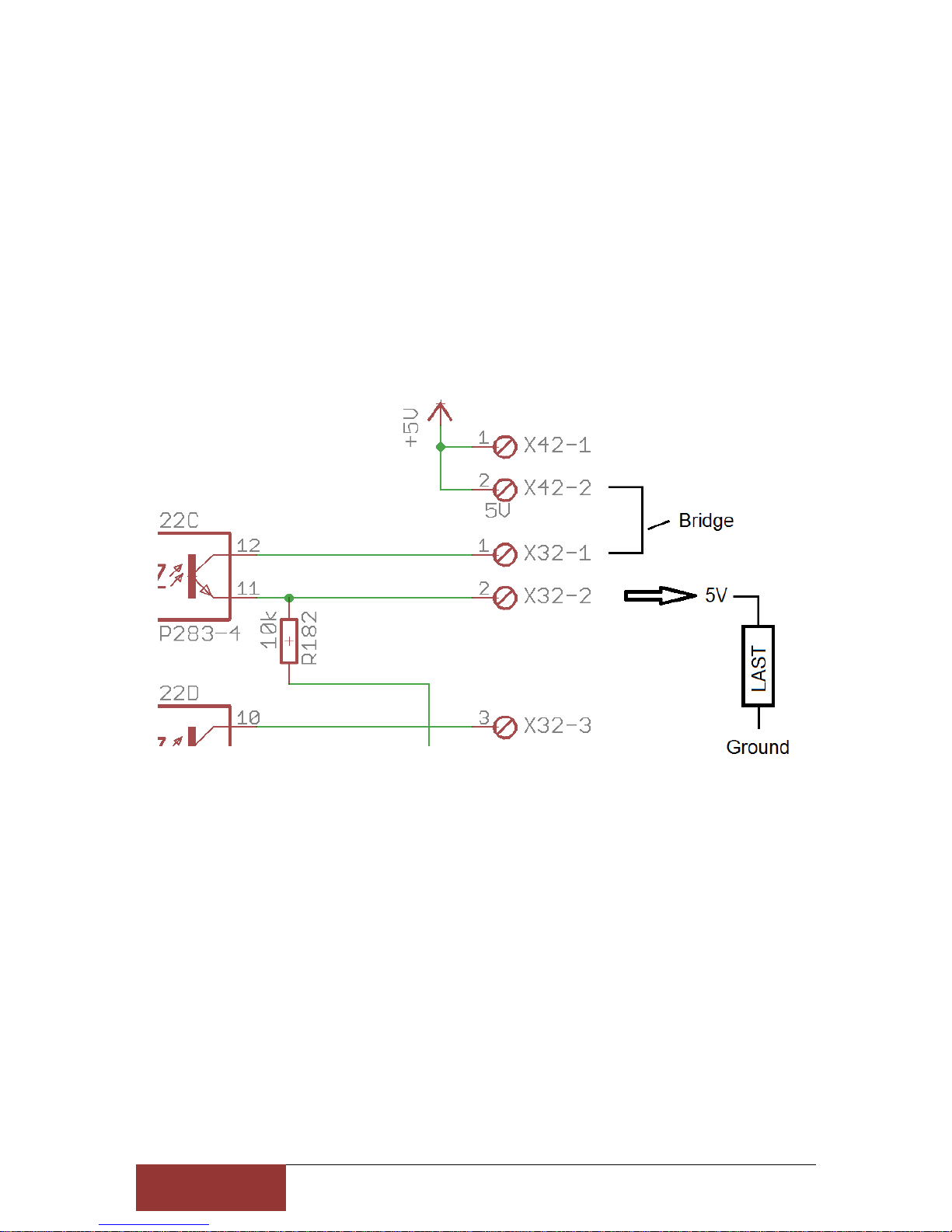
Outputs
Like the input port, each output port is also provided with a pin number and an associated *
(output)
example
X32-1 is Number 6 = Port2/Pin6 and
X32-2 is Number 6* = Port2/Pin6
For 5V sensors, relays or similar loads you can put a bridge of 5V on the respective pin
number, so you can use a power supply
For switching max 50mA per output are available. If you need higher currents for switching
you can connect inexpensive relay modules.
You can connect to any pin without * a direct voltage, max to 30V

9
Stefan Gemeinert,Frühlingstrasse 8 85253 Erdweg
Tel: 081386695536 www cnc-technics de
Integrate Outputs in Mach3
The Port Number and the Pin Number are used, the hook at enabled to enable output

1
0
Stefan Gemeinert,Frühlingstrasse 8 85253 Erdweg
Tel: 081386695536 www cnc-technics de
Set Axes in Mach3/UCCNC
These are fixed values that should not be changed

1
1
Stefan Gemeinert,Frühlingstrasse 8 85253 Erdweg
Tel: 081386695536 www cnc-technics de
Driver Connection

1
2
Stefan Gemeinert,Frühlingstrasse 8 85253 Erdweg
Tel: 081386695536 www cnc-technics de
Set spindle
Port 1 / Pin 1 is the analog output for the spindle speed
A VFD frequency inverter for the analogue signal can be connected to the spindle output Via
jumper 1-2 = 5V or bridge 2-3 = 10V output signal at bridge
The Potentiometer R13 should not be adjusted he is set so that at 5V PWM output from the
PC comes a 10V analog signal

1
3
Stefan Gemeinert,Frühlingstrasse 8 85253 Erdweg
Tel: 081386695536 www cnc-technics de
Spindle direction

1
4
Stefan Gemeinert,Frühlingstrasse 8 85253 Erdweg
Tel: 081386695536 www cnc-technics de
CW (clockwise) or CCW (counterclockwise) are switchable relay outputs

1
5
Stefan Gemeinert,Frühlingstrasse 8 85253 Erdweg
Tel: 081386695536 www cnc-technics de
Spindle in UCCNC

1
6
Stefan Gemeinert,Frühlingstrasse 8 85253 Erdweg
Tel: 081386695536 www cnc-technics de
Relaisoutput
There are 4 Relay Outputs up to 230V / max 10A (2,2KW at 230V) available
PORT 2 Pin 1,14,16 oder 17
Attention: do not connect switching power supplies because they have a very high inrush
current, the relay contacts may be defective

1
7
Stefan Gemeinert,Frühlingstrasse 8 85253 Erdweg
Tel: 081386695536 www cnc-technics de
Statusdisplay

1
8
Stefan Gemeinert,Frühlingstrasse 8 85253 Erdweg
Tel: 081386695536 www cnc-technics de
Charge Pump
This setting can be enabled or disabled
If the jumper is set to 1/2 the board will be activated without protection and all will remain
Tensions and controls are maintained even if Mach3 makes a reset
If the jumper is set to 2/3, the breakout board will be controlled by Mach3 via the 12 5Khz
signal That is, only after the reset of Mach3 is deactivated, the board is active All
components are supplied with 5V or 12V For this you have to make the following settings in
Mach3:

1
9
Stefan Gemeinert,Frühlingstrasse 8 85253 Erdweg
Tel: 081386695536 www cnc-technics de
Table of contents
Popular Control Unit manuals by other brands


DeZurik
DeZurik KSL-SD instructions

VIA Technologies
VIA Technologies VX800 Series Programming manual

National Instruments
National Instruments FIeldPoint FP-AO-200 operating manual

Powers
Powers Hydroguard 410 5 Technical instructions

SIGNALCORE
SIGNALCORE SC5406B Operating & programming manual

SVF
SVF B42C Series Installation operation & maintenance

Siemens
Siemens VAG60 Series Mounting instructions

Vega
Vega VEGACAL 60 Series operating instructions

Keeson
Keeson MC120PR Product Function Instruction

Whelen Engineering Company
Whelen Engineering Company CenCom Core-S C399S installation guide

oventrop
oventrop Cocon 2TZ installation instructions

SMC Networks
SMC Networks 5100 IT Series manual