Powers Hydroguard 410 5 Owner's manual

DESCRIPTION
The Series 410 Hydroguard is a pressure compensating mixer
which delivers a predetermined water temperature, compen-
sating for pressure fluctuations in the hot or cold water supply.
The Series 410 Hydroguard features a poppet-type equaliz-
ing valve as part of a replaceable cartridge. The poppet-type
construction offers a distinct advantage, it will not stick
because of lime build-up or foreign particles in the supply.
The adjustable maximum temperature stop prevents acci-
dental scalding caused by overadjustment of the handle.
Many Series 410 valves and shower systems can be select-
ed to meet the Americans with Disabilities Act (ADA) [see
back page for details].
SPECIFICATIONS
Operating
Capacity: Shower and Tub
6 gpm at 45 psi differential [22.7 L/min at 310 kPa]
Maximum Static Pressure...................125 psi [862 kPa]
Maximum Inlet Temperature .....................180°F [82°C]
Inlet and Outlet Sizes ................................1/2″NPT
Roughing-in Template..............................All Models
Maximum Temperature Adjustment................All Models
Complies to ASSE 1016 & CSA B125.....................All Models
APPLICATION
The Series 410 Hydroguard is particularly recommended in
showers and shower bath installations for motels, hotels,
dormitories, and high rise apartment buildings.
OPERATION (SEE FIGURE 1)
Hot and cold water enter their respective ports and the pres-
sures are equalized through the action of the balance poppet
(1). The entire balancing poppet assembly is contained in a
Celcon chamber (2). This chamber is replaceable as a com-
plete cartridge. After the hot and cold pressures are equal-
ized, they are mixed by the action of a mixing plate (3). As
the temperature adjustment stem is rotated from shutoff to
maximum hot water temperature, the mixing plate passes
the required proportion of hot and cold water to produce the
control point. With the adjustment stem in its full clockwise
position, shutoff is obtained by closing both supplies.
The maximum temperature stop (4) allows the user to set the
maximum discharge temperature. This mixer does not recog-
nize supply water temperature changes, so any variation in
the water temperature will affect the control point and the
maximum temperature setting.
NOTE: Following any maintenance of unit, maximum
temperature stop must be reset. See page 5 for instruc-
tions.
TECHNICAL INSTRUCTIONS
Hydroguard Series 410 Valves
Model 5 and Model 8
Form TI410-5 v3
2
Celcon Chamber
4
Maximum
Temperature
Stop
Bonnet
Hot Water Supply
1
Balancing
Poppet
Assembly
Cold Water Supply 3
Mixing Plate
;;
;;
;;
Stem
FIGURE 1 – OPERATION
411/416

MAINTENANCE
Troubleshooting
What to look for:
1. The flow of water is less than desired.
a. Valves upstream from supply not fully open.
b. Low supply pressures.
c. Accumulation of lime deposits in hot water pipes,
restricting the flow of hot water.
d. Showerhead clogged.
e. Checkstops may not be fully open.
f. Low supply temperature (Hot Water).
2. Flow of water is completely shut off.
a. Valves upstream from supply completely closed.
b. Failure of hot or cold water supply pressure. The
Hydroguard is constructed to restrict the flow of water
on hot or cold water supply failure.
c. Checkstops closed.
3. Flow is untempered hot or cold water.
a. The water supplies are connected to the wrong ports.
b. Diaphragm is ruptured; replace with new cartridge.
c. Check for foreign material that may be clogging the
cartridge.
4. Flow of water continues when Hydroguard is shut off.
a. Worn shut-off discs. Replace worn disc.
b. Scratched mixing plate.
c. Erosion. Contact a Powers applications engineer to
order replacement parts.
5. Maximum temperature is too low.
a. Accumulation of lime deposits in hot water pipes,
which restricts the flow of hot water.
b. The concealed maximum temperature limit stop is not
at its maximum adjustment. See page 5 to set the
maximum temperature limit stop.
c. Hot water temperature is too low.
6. Standard inlets are desired.
See Figure 2 for instructions on standard inlets (with cold
water entering the COLD port). With mixer in closed posi-
tion, the notch in the top spline on the stem must FACE
the outlet.
7. Reversed inlets are desired.
See Figure 3 for instructions on reversing the mixing plate
(with cold water entering HOT port). For reversed inlets,
the notch must face AWAY FROM the outlet port.
Note: When using reversed inlets, the HOT and COLD
inlets should be identified to avoid confusion during
future maintenance.
TI410-5 v3 Page 2
HOT
COLD
COLD
Outlet
Orientation of Plate and Stem Assembly
for STANDARD Inlets
(Cold Water into Cold port)
Must Point
to COLD Inlet
Notch in Handle
Spline
Must FACE TOP
Water
HOT
Water
C
FIGURE 2 – STANDARD INLETS
HOT
COLD
HOT
Outlet
Orientation of Plate and Stem Assembly
for REVERSED Inlets
(Cold Water into Hot port)
Must Point
to HOT Inlet
Notch in Handle
(Top) Spline
Must Face AWAY
From Outlet
Water
COLD
Water
C
FIGURE 3 – REVERSED INLETS

TI410-5 v3 Page 3
FRONT FINISH
E
D
WA
L
LG
UI
DE
TRI-HANDLE ASSEMBLY
(All Models: 1-8)
5c
5b
5a
LEVER HANDLE ASSEMBLY
(Model 8) ACRYLIC HANDLE ASSEMBLY
(Model 8)
2b
2a
HOT
POWERS
5COLD
U7
Model
Number Date
Code
5U7
Model
4
0
1
-
0
0
0
P
a
r
t
N
o
.
See Nameplate to determine your valve model:
11
9
10a
10b
27
26
25
28
23
22
25
25A
28
24
21 21A
20
13
19
18
18A
17
15
13
12
14 16
ABOVE: Parts 11-28 in Valve body
BELOW: Parts 11-28 Detailed
10
4e
4b
4a
4d
4c
†Used on 4-port mixers only.
No discharge will occur when used
in a 3-port mixer.
R
H
C
678
PARTS
KIT KIT NUMBER KIT KIT NUMBER
Lever Handle Assembly Kit (Model 8) 410-448
Items 2a-2b (Qty: 1 each), 6
Acrylic Handle Assembly Kit (Model 8) 410-447
Items 4a-4e (Qty: 1 each), 6
Tri-Handle Assembly Kit 410-565
Items 5a-5d (Qty: 1 each)
Dial Assembly Kit, Standard 410-445
Items 7, 9, 10a, 10, 8
Dial Plates (bulk pack) 410-413BP
Item 10 (Qty: 15)
Dial Plates (jumbo bulk pack) 410-413JP
Item 10 (Qty: 25)
Retainers (bulk pack) 410-367
Item 7 (Qty: 10)
Balancing Cartridge Kit (3-port) 410-183
Items 18, 22, 23, 24†, 25, 26
Balancing Cartridge Kit (4-port) 401-175
Items 18, 22, 23, 24†, 25, 26
Flat Washers (bulk pack) 410-368
Item 20 (Qty: 15)
Wavy Washers (bulk pack) 410-369
Item 19 (Qty: 10)
Gasket and Disk Replacement Kit 410-182
Items 13, 18, 18a, 22, 23, 24†, 25
O-Rings (bulk pack) 410-366
Item 13 (Qty: 25)
Oversize 410 Inlet Seal Kit 410-570
10a, 13, 22, 23, 24, 25, 25A
Screws, for dial plate (bulk pack) 420-216
Item 9 (Qty: 20)
Throttling Stem/Plate Replacement Kit 410-378
Items 13, 18, 18a, 19, 20, 21, 22
† For use on 4-port mixers only. No discharge will occur when used in 3-port mixers.
* Sleeve (401-253) used on 419’s only (not shown).

TI410-5 v3 Page 4
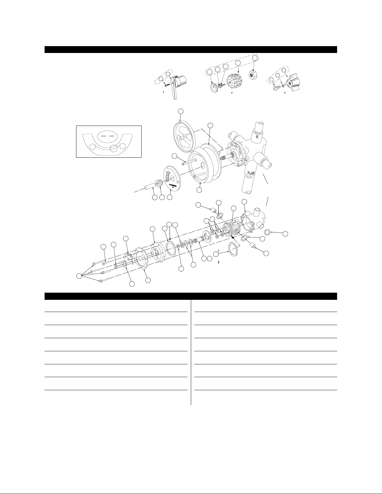
PARTS – SERIES 410 HYDROGUARD
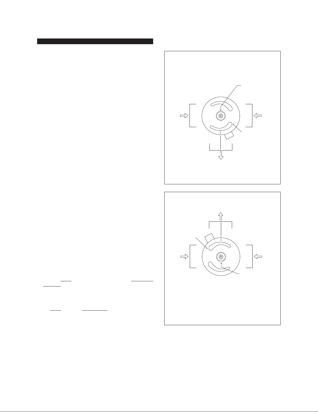
Series 410 Hydroguard Pressure equalizing mixer. Poppet-type construction. Adjustable maximum temperature stop.
Item Part Description Part No. Quantity Material
2a-2b Lever Handle Assembly (410 Model 8) see kit #410-448
2a Lever Handle Screw (8-32 x 1-1/4") * 1 C.P. Brass
2b Lever Handle * 1 C.P. Zinc
4a-4e Acrylic Handle Assembly (410 Model 8) see kit # 410-447
4a Plug Button and Insert 420-314 1 C.P. Brass
4b Acrylic Handle Screw (8-32 x 3/4") 034-515K 1 C.P. Brass
4c Washer 227-197 1 Neoprene
4d Control Knob/Sleeve Assembly 420-310 1 Acrylic and Brass
4e Acrylic Handle Insert 420-125 1 C.P. Zinc
5a-5d Tri-Handle Assembly (All 410 Models: 1-8) see kit # 410-565
5a Tri-Handle Screw 030-070 1 C.P. Zinc
5b Washer 046-008K 1 C.R. Steel
5c Tri-Handle 410-191 1 C.P. Brass
5d Plug Button (not shown) 410-195 1 --
6 Sleeve 401-267 1 C.P. Copper
7 Retainer for Brass Stamped Standard Dial see kit # 410-367
7a Retainer for Brass Stamped Deluxe Dial 410-417 1 Rubber
8 Dial Insert (Model 5) (not shown) 410-374 1 Aluminum
Graphic Insert (not shown) 410-442 1
9 Screws (2) see kit # 420-216
10 Dial Plate see kit # 410-445
10a Gasket see kit # 410-570
10b Rough-in Guide (All Models) 401-178 1 -
11 Bonnet Screws (10-32 x 1") (4) 030-885 4 Stainless Steel
12 Adjustment Stop Screw (10-32 x 5/16") 030-884 1 Stainless Steel
13 O-Rings (3/8" x 1/2" x 1/16") (2) see kit # 410-182/410-570/410-378 1
14 Maximum Temperature Stop 401-218 1 Brass
15 Adjustment Stop 401-278 1 Stainless Steel
16 Support Ring 410-377 1 Stainless Steel
17 Bonnet 401-162 1 Noryl
17a Bonnet for 414 Valve (not shown) 410-393 1 Noryl
18 Bonnet Gasket (Rainbow Style) see kit # 410-182/410-378
18a Bonnet O-Ring (Models 1-3 only) (not shown) see kit # 410-182/410-378
19 Wavy Washer see kit # 410-378/410-369
20 Flat Washers (4) see kit # 410-368/410-378
21 Throttling Stem see kit #410-378
21a Throttling Stem for 419 Valve (not shown) 410-378A 1 Brass Stem Celcon Plate
22 Shut-off Discs (2) see kit # 410-570/378, 182, 183, 401-175
23 Quad Rings (2) see kit # 410-570, 182, 183, 401-175
24† O-Ring (1-3/4" x 1-7/8" x 1/16")† see kit # 410-570, 182, 183, 401-175
25 O-Rings (1-3/4" x 1-3/16" x 3/32") (2) see kit # 410-570, 182, 183, 401-175
25A O-Ring (oversized) see kit # 410-570
26 Balance Chamber (3-port valves) see kit # 410-183
Balance Chamber (4-port valves) see kit # 401-175
27 Body, 4-Port N/A
Body, 3-Port (not shown) N/A
† For use on 4-port mixers only. No discharge will occur when used in 3-port mixers.

TI410-5 v3 Page 5
SERVICING
1. Shut off upstream water supply.
2. Remove the dial assembly and handle. See page 3 for rela-
tionship of parts. Unscrew four cap screws and remove
cap assembly by gently pulling on stem.
3. TO REMOVE THE BALANCE CHAMBER, using a balance
chamber extraction tool (Part No. 401-202) is highly recom-
mended. To use the extraction tool, follow instructions
below:
a. Insert hooked ends of extraction tool into HOT and
COLD outlet ports of the balance chamber (see Figure
4).
b. Insert screwdriver down through end of extraction tool.
c. Place a wood or plastic block (do not use metal)
between screwdriver and valve body. Firmly ease
screwdriver away and downward, using wood for
added leverage as cartridge is gradually pulled out.
4. Replace necessary items and reassemble. A small amount
of silicone gel on the cartridge, O-rings, and related sur-
faces will aid in the assembly.
CAUTION: Do not pinch cartridge O-rings during assembly.
5. Replace bonnet with new bonnet gasket. Proceed to step 6
to reset maximum temperature setting.
MAXIMUM TEMPERATURE SETTING
6. MAXIMUM TEMPERATURE SETTING (refer to Figure 5).
This must be set on the job and following any maintenance
or servicing to the valve. Mixer is factory set to pass full
HOT water.
a. Loosen adjustment stop screw (do not remove).
Gradually rotate stem counterclockwise to get desired
maximum water temperature. (Maximum Temperature
Stop will rotate along with the stem when the stem is
rotated.)
b. Once stem has been rotated to desired temperature,
slide adjustment stop clockwise until fin on adjustment
stop touches the maximum temperature stop.
c. While holding adjustment stop in place, tighten adjust-
ment stop screw.
d. Replace handle. Confirm maximum temperature has
been set properly by operating the valve using the
handle.
CAUTION: Adjustment stop must be present for proper operation.
FIGURE 5 – MAXIMUM TEMPERATURE SETTING
FIGURE 4 – BALANCE CHAMBER REMOVAL
Adj. Stop Screw
Adjustment Stop
Fin
Adjustment Stem
Maximum
Temperature
Stop
Balance
Chamber
Extraction
Tool

TI410-5 v3 Page 6
1. Cartridge slips while seated in body.
2. Flow of water continues after mixer is turned off,
and all other seals have been replaced.
410-570 Items 13, 22, 23, 24, 25, 25A
(also includes oversize O-ring for use with
Models 1-8)**
1. To convert to Model 8 lever or acrylic handle. 410-445 Items 7,9,10a, 10, 8
410-448 Items 2a-2b, 6
410-447 Items 4a-4e, 6
1. Water leaks at stem and/or bonnet.
2. Flow of water continues after mixer is turned off.
410-182 Items 13, 18, 18a 22, 23, 24,* 25
(includes bonnet O-ring for Models 1-3)
1. Variable or untempered discharge temperature.
401-175 Items 18, 22, 23, 24*, 25, 26, 28
410-183 Items 18, 22, 23, 24*, 25, 26, 28
1. Flow continues after mixer is turned off.
2. Handle splines on stem damaged.
410-378 Items 13, 18, 18a 19, 20, 21, 22
(includes bonnet O-ring for Models 1-3)
Oversize 410 Inlet
Seal Kit**
Dial Assembly Kit
Lever Handle Kit
Acrylic Handle Kit
Gasket and Disc
Replacement
Balance Chamber (3-port)
Balance Chamber (4-port)
Throttling Stem and Plate
Replacement
Recommended Repair KitDescription Kit Number and Contents
*
Use item 24 only in 4-port model.
No discharge will occur if item 24 is used in 3-port model.
** When using oversize O-ring, discard ONE of the two regular sized O-rings normally used and use oversize O-ring in its place.
4-port valve models are: P416 and P417.
3-port valve models are: P411, P412, P413, P414 and P419.
Notes:
1. Use silicone provided on all O-rings and related surfaces. Never use grease.
2. Some kits contain parts for all models; discard extra parts as appropriate.
†
†
†
TROUBLESHOOTING
HOT COLD
OFF
38" (typical)
[96.5 cm]
48" (typical)
[121.9 cm]
ADA-COMPLIANT OPTIONS
When used together, Powers’lever handle and handshower
meet ADA compliance standards. For complete ADA-
required heights and other information on installing an ADA-
compliant bathing system, refer to the ADAAG (Americans
with Disabilities Act Accessibility Guidelines).

TI410-5 V2 Page 7
NOTES

TI410-5 V2 Page 8
Form TI410-5 v3 0310 6511202 PRINTED IN U.S.A.
USA office: Phone: 800.669.5430 • Fax: 847.824.0627
www.powerscontrols.com
Canadian office: Phone: 888.208.8927 • Fax: 888.882.1979
© 2003 Powers, a Watts Industries Co.
A Watts Industries Co.
NOTES
This manual suits for next models
2
Table of contents
Other Powers Control Unit manuals

Powers
Powers BILTMORE 800 SERIES User manual

Powers
Powers F727 Owner's manual

Powers
Powers IntelliStation Jr User manual

Powers
Powers Biltmore 900 Series Owner's manual

Powers
Powers HydroGuard ES150XBY Owner's manual

Powers
Powers HydroGuard 400 Series How to use

Powers
Powers HydroGuard e427 Series Owner's manual

Powers
Powers LFLM49 Series User manual

Powers
Powers HydroGuard LFLM490 User manual

Powers
Powers HydroGuard XP Series LFSH1430 Owner's manual