CND VS-MIDI User manual

VS
VSVS
VS-
--
-MIDI
MIDIMIDI
MIDI
MIDI Interface for
MIDI Interface forMIDI Interface for
MIDI Interface for
Vermona Synthesizer
Vermona SynthesizerVermona Synthesizer
Vermona Synthesizer
Model 8
Model 8Model 8
Model 8-
--
-434
434434
434
Version 2.0
Version 2.0Version 2.0
Version 2.0
Owner’s Manual
Owner’s ManualOwner’s Manual
Owner’s Manual
© 2022 CHD Elektroservis
© 2022 CHD Elektroservis© 2022 CHD Elektroservis
© 2022 CHD Elektroservis
www.chd
www.chdwww.chd
www.chd-
--
-el.cz
el.czel.cz
el.cz

Vermona Synthesizer MIDI Interface
Vermona Synthesizer MIDI InterfaceVermona Synthesizer MIDI Interface
Vermona Synthesizer MIDI Interface
VS
VS VS
VS-
--
-MIDI
MIDIMIDI
MIDI Owner‘s
Owner‘s Owner‘s
Owner‘s Manual
Manual Manual
Manual
8
88
8-
--
-434 / v. 2.00
434 / v. 2.00434 / v. 2.00
434 / v. 2.00
Copyright © 2022 CHD Elektroservis. All rights reserved.
No part of this publication may be reproduced in any form without the written permission of CHD Elektroservis.
2
2
2
2
Contents
ContentsContents
Contents
Page
PagePage
Page
1
11
1 FEATURES
FEATURESFEATURES
FEATURES................................
................................................................
................................................................
................................................................
................................................................
................................................................
................................................................
................................................................
.....................................................
..........................................
..................... 3
33
3
2
22
2 CONNECTION TO MIDI SYSTEM
CONNECTION TO MIDI SYSTEMCONNECTION TO MIDI SYSTEM
CONNECTION TO MIDI SYSTEM................................
................................................................
................................................................
................................................................
................................................................
................................................................
........................................................
................................................
........................ 3
33
3
2.1 STANDARD WORKING MODE SET-UP...............................................................................................................3
2.2 INTERFACE MEMORY BACK-UP SET-UP............................................................................................................. 3
3
33
3 INTERFACE OPERATION
INTERFACE OPERATIONINTERFACE OPERATION
INTERFACE OPERATION................................
................................................................
................................................................
................................................................
................................................................
................................................................
................................................................
................................................................
..................................
....
.. 4
44
4
3.1 RESET STATUS............................................................................................................................................... 4
3.2 MIDI MODE.................................................................................................................................................. 4
4
44
4 INTERFACE PARAMETERS
INTERFACE PARAMETERSINTERFACE PARAMETERS
INTERFACE PARAMETERS................................
................................................................
................................................................
................................................................
................................................................
................................................................
................................................................
................................................................
................................ 5
55
5
4.1 INTERFACE GLOBAL SYSTEM PARAMETERS.......................................................................................................5
4.1.1 MIDI CHANNEL ............................................................................................................................................. 5
4.1.2 VCF CC Nr..................................................................................................................................................... 5
4.1.3 VCA CC Nr. ................................................................................................................................................... 6
4.1.4 EG BREAK PULSE DURATION........................................................................................................................... 6
4.1.5 VCO CALIBRATION CONSTANT ........................................................................................................................ 6
4.2 INTERFACE PATCH PARAMETERS.....................................................................................................................6
4.2.1 VCO MIDI NOTES SHIFT (CC #16) ..................................................................................................................... 7
4.2.2 VCO PITCH BEND RANGE (CC #17)................................................................................................................... 7
4.2.3 VCF CONTROL MODE (CC #18) ........................................................................................................................ 7
4.2.4 VCF KEY FOLLOW (CC #19).............................................................................................................................. 8
4.2.5 VCF VELOCITY AMOUNT (CC #20).................................................................................................................... 9
4.2.6 VCF CHNL AFTERTOUCH AMOUNT (CC #21) ......................................................................................................9
4.2.7 VCA CONTROL MODE (CC #22)........................................................................................................................ 9
4.2.8 VCA KEY FOLLOW (CC #23) ............................................................................................................................. 9
4.2.9 VCA VELOCITY AMOUNT (CC #24).................................................................................................................... 9
4.2.10 VCA CHNL AFTERTOUCH AMOUNT (CC #25).................................................................................................... 10
4.2.11 EG RETRIGGER MODE (CC #26)...................................................................................................................... 10
4.2.12 EG RETRIGGER RATE (CC #27) ....................................................................................................................... 10
4.2.13 INDICATOR MODE (CC #28) .......................................................................................................................... 10
5
55
5 MIDI IMPLEMENTATION
MIDI IMPLEMENTATIONMIDI IMPLEMENTATION
MIDI IMPLEMENTATION ................................
................................................................
................................................................
................................................................
................................................................
................................................................
...............................................................
..............................................................
............................... 11
1111
11
5.1 CHANNEL COMMANDS................................................................................................................................ 11
5.1.1 NOTE ON/OFF............................................................................................................................................. 11
5.1.2 MIDI CONTROL CHANGES (CCs)..................................................................................................................... 11
5.1.2.1 STANDARDIZED CONTROLLERS...................................................................................................................... 12
5.1.2.2 CONTROLLERS FOR INTERFACE PATCH PARAMETERS EDITING........................................................................... 13
5.1.3 CHANNEL (MONO) AFTERTOUCH................................................................................................................... 14
5.1.4 PITCH BEND................................................................................................................................................ 14
5.1.5 PROGRAM CHANGE..................................................................................................................................... 14
5.2 COMMON SYSTEM COMMANDS................................................................................................................... 15
5.2.1 CLOCK ....................................................................................................................................................... 15
5.2.2 RESET........................................................................................................................................................ 15
5.3 SYSTEM EXCLUSIVE MESSAGES...................................................................................................................... 15
5.3.1 STRUCTURE OF SYSEX COMMUNICATION....................................................................................................... 15
5.3.2 SUPPORT FOR SYSEX MESSAGES CREATION .................................................................................................... 16
6
66
6 APPENDICES
APPENDICESAPPENDICES
APPENDICES ................................
................................................................
................................................................
................................................................
................................................................
................................................................
................................................................
................................................................
...............................................
..............................
............... 17
1717
17
6.1 LIMITATION OF THE INTERFACE OPERATION................................................................................................... 17
6.2 ERROR STATUS INDICATION.......................................................................................................................... 17
6.3 ERRORS CAUSED BY MIDI LOOP..................................................................................................................... 17
6.4 EG BREAK PULSE DURATION ADJUSTMENT..................................................................................................... 17
6.5 VCO CV CALIBRATION.................................................................................................................................. 17
6.6 MIDI IMPLEMENTATION CHART .................................................................................................................... 18
6.7 CONVERSION TABLES................................................................................................................................... 19
6.8 TECHNICAL SPECIFICATION........................................................................................................................... 22
6.9 WARRANTY CONDITIONS ............................................................................................................................. 22
6.10 IMPORTANT SAFETY INSTRUCTIONS .............................................................................................................. 23

Vermona Synthesizer MIDI Interface
Vermona Synthesizer MIDI InterfaceVermona Synthesizer MIDI Interface
Vermona Synthesizer MIDI Interface
VS
VS VS
VS-
--
-MIDI
MIDIMIDI
MIDI Owner‘s
Owner‘s Owner‘s
Owner‘s Manual
Manual Manual
Manual
8
88
8-
--
-434 / v. 2.00
434 / v. 2.00434 / v. 2.00
434 / v. 2.00
Copyright © 2022 CHD Elektroservis. All rights reserved.
No part of this publication may be reproduced in any form without the written permission of CHD Elektroservis.
3
3
3
3
1
11
1
FEATURES
FEATURESFEATURES
FEATURES
VS-MIDI is a MIDI retrofit for Vermona Synthesizer. The VS-MIDI interface controls VCO, EG, VCF and VCA
circuits of the Vermona Synthesizer via MIDI commands.
The interface only receives MIDI data and converts them to signals for the Vermona Synthesizer control. The
instrument’s own control elements (keyboard, switches, knobs, etc.) are not transmitted as a MIDI data and
their status cannot be saved in the interface’s memory as a patch.
All functions of the interface are simply controlled by standard MIDI commands (CCs, Program Change, etc.).
Some special functions controlled by MIDI SysEx messages are available for advanced users.
The interface has internal memory for saving of interface’s own settings. Content of the memory can be backed
up in any MIDI DAW, sequencer, etc.
2
22
2
CONNECTION TO MIDI S
CONNECTION TO MIDI SCONNECTION TO MIDI S
CONNECTION TO MIDI SYSTEM
YSTEMYSTEM
YSTEM
The interface has connectors for both MIDI data input and output. Standard MIDI cables
1
11
1
are used to connect
other MIDI devices.
2.1
2.12.1
2.1
STANDARD WORKING MODE SET
STANDARD WORKING MODE SETSTANDARD WORKING MODE SET
STANDARD WORKING MODE SET-
--
-UP
UPUP
UP
Fig. 1
Fig. 1 Fig. 1
Fig. 1 –
––
– Connection to MIDI system
Connection to MIDI system Connection to MIDI system
Connection to MIDI system for standard working mode
for standard working modefor standard working mode
for standard working mode
Data from the host
MIDI system (PC,
DAW, sequencer,
master keyboard,
etc.) are coming to
MIDI-IN input of the
interface.
All MIDI data
2
22
2
coming to the MIDI input are transferred unaffected to MIDI-THRU/OUT output of the interface (THRU
function). The THRU function enables another MIDI device(s) to be connected without additional MIDI Thru-
Box. MIDI input of the other (next in chain) MIDI device can be simply fed from MIDI-THRU/OUT output of the
interface (see fig. 1).
If there are no other MIDI devices to be used, only MIDI-IN cable is necessary (from MIDI output of host system
to MIDI-IN input of the interface).
2.2
2.22.2
2.2
INTERFACE MEMORY BACK
INTERFACE MEMORY BACKINTERFACE MEMORY BACK
INTERFACE MEMORY BACK-
--
-UP SET
UP SETUP SET
UP SET-
--
-UP
UPUP
UP
Fig. 2
Fig. 2 Fig. 2
Fig. 2 –
––
– Connection to MIDI system
Connection to MIDI system Connection to MIDI system
Connection to MIDI system for memory content transfer
for memory content transferfor memory content transfer
for memory content transfer
The interface can transmit its own MIDI System
Exclusive data. These messages are used for
back-up / recovery of the internal memory
settings.
To back-up the memory of the interface, connect
interface’s THRU/OUT MIDI output to MIDI input
of the host system (PC, DAW, sequencer…)
3
33
3
(see
fig. 2).
1
The cables equipped with DIN 41524 connectors (5 pins / 180°).
2
All MIDI data except own specific System Exclusive messages for the VS-MIDI interface. These System Exclusive messages are filtered.
3
Attention!
Attention!Attention!
Attention! Disable the MIDI ECHO, THRU, … functions of your sequencer in this case to prevent communication loops that might “freeze” your MIDI
system (see chapter 6.3)!
Vermona Synthesizer MIDI Interface
Vermona Synthesizer MIDI InterfaceVermona Synthesizer MIDI Interface
Vermona Synthesizer MIDI Interface
VS
VS VS
VS-
--
-MIDI
MIDIMIDI
MIDI Owner‘s
Owner‘s Owner‘s
Owner‘s Manual
Manual Manual
Manual
8
88
8-
--
-434 / v. 2.00
434 / v. 2.00434 / v. 2.00
434 / v. 2.00
Copyright © 2022 CHD Elektroservis. All rights reserved.
No part of this publication may be reproduced in any form without the written permission of CHD Elektroservis.
4
44
4
3
33
3
INTERFACE OPERATION
INTERFACE OPERATIONINTERFACE OPERATION
INTERFACE OPERATION
The interface doesn’t have any manual control element. All functions of the interface are controlled by
interfaces parameters (see chapter 4). The parameters can be set / adjusted by MIDI commands only. Most of
them are simply set by MIDI Control Changes - CCs (see chapter 5.1.2).
Working status of the interface is indicated by bi-color LED. The indication LED is placed under the “MAINS“
switch on the instrument’s front panel. The LED lights red in quiescent condition – it indicates power-on status
of the Vermona Synthesizer instrument. An interface activity can be indicated by the yellow light of the
indication LED. Mode of the LED indication is user selectable (see chapter 4.2.13). If there is an error occurred,
the indication LED starts to blink periodically (see chapter 6.2).
3.1
3.13.1
3.1
RESET STATUS
RESET STATUSRESET STATUS
RESET STATUS
When the Vermona Synthesizer instrument is switched on, the interface is disabled (it does not affect the
instrument) and the instrument can be used usual way like no MIDI interface has been installed. The interface is
now monitoring the incoming MIDI data.
3.2
3.23.2
3.2
MIDI MODE
MIDI MODEMIDI MODE
MIDI MODE
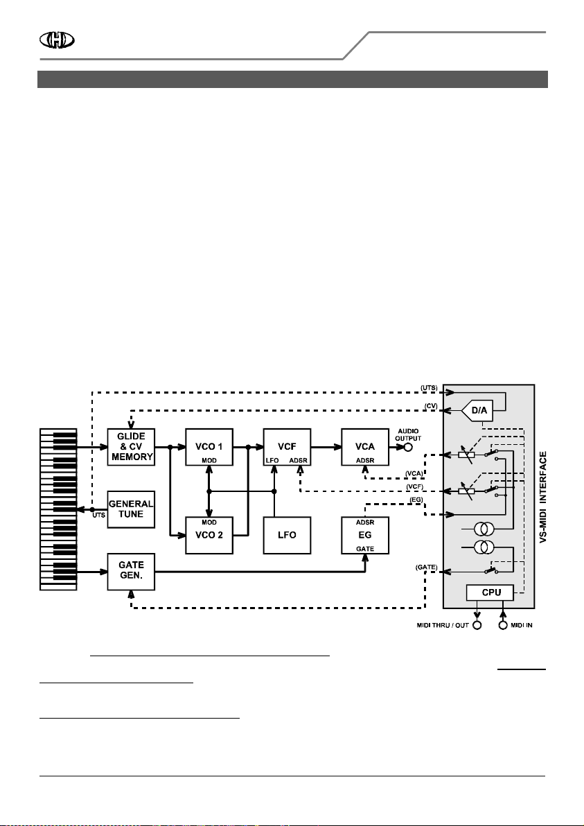
When an acceptable MIDI command (see chapter 5) is received, the interface turns to MIDI mode automatically
and takes control over instrument’s circuits (see fig. 3) accordingly to the incoming MIDI data.
Fig. 3
Fig. 3 Fig. 3
Fig. 3 –
––
– MIDI mode block diagram
MIDI mode block diagram MIDI mode block diagram
MIDI mode block diagram
After that, the instrument’s own keyboard can not be used yet
4
44
4
! All knobs and switches of the instrument still
work the standard way. If you want to use the instrument’s own keyboard again, you have to switch the
instrument off and then on again after a moment
5
55
5
.
4
Simultaneous usage of MIDI Notes and instrument’s own keyboard causes that the instrument is playing considerably out of tune (see chapter 6.1)!
5
Interface reset can be also executed by the MIDI common system command “Reset” or by System Exclusive message “HW Reset” (see MIDI SysEx
Communication manual).

Vermona Synthesizer MIDI Interface
Vermona Synthesizer MIDI InterfaceVermona Synthesizer MIDI Interface
Vermona Synthesizer MIDI Interface
VS
VS VS
VS-
--
-MIDI
MIDIMIDI
MIDI Owner‘s
Owner‘s Owner‘s
Owner‘s Manual
Manual Manual
Manual
8
88
8-
--
-434 / v. 2.00
434 / v. 2.00434 / v. 2.00
434 / v. 2.00
Copyright © 2022 CHD Elektroservis. All rights reserved.
No part of this publication may be reproduced in any form without the written permission of CHD Elektroservis.
5
5
5
5
4
44
4
INTERFACE PARAMETERS
INTERFACE PARAMETERSINTERFACE PARAMETERS
INTERFACE PARAMETERS
Fig. 4
Fig. 4 Fig. 4
Fig. 4 –
––
– Interface’s parameter memory structure
Interface’s parameter memory structure Interface’s parameter memory structure
Interface’s parameter memory structure
The parameters are
divided in two basic
groups – interface
global (system)
parameters and
interface patch
parameters (see fig. 4).
All interface
parameters are stored
in user accessible internal memory of the interface. There is one memory for the global parameters and 32
memories for the interface patch parameters available.
4.1
4.14.1
4.1
INTERFACE GLOBAL SYSTEM PARAMETERS
INTERFACE GLOBAL SYSTEM PARAMETERSINTERFACE GLOBAL SYSTEM PARAMETERS
INTERFACE GLOBAL SYSTEM PARAMETERS
Interface global parameters control the basic functions and hardware of the interface. The global parameters
are always valid independently on the actually selected patch of the interface. They are automatically loaded
from the memory during reset sequence of the interface.
Values of the global parameters can be changed by MIDI SysEx Messages only (please see the MIDI SysEx
Communication manual for details). Factory pre-defined values of the global parameters are listed in the table
below.
Table 1
Table 1 Table 1
Table 1 –
––
– Range of valid values and factory preset values of global parameters
Range of valid values and factory preset values of global parameters Range of valid values and factory preset values of global parameters
Range of valid values and factory preset values of global parameters
Factory preset
Factory presetFactory preset
Factory preset
Parameter name
Parameter nameParameter name
Parameter name
Valid range
Valid rangeValid range
Valid range
Value
ValueValue
Value
Meaning
MeaningMeaning
Meaning
Chapter
ChapterChapter
Chapter
MIDI Channel 0 ~ 15 0 MIDI Channel Nr. 1 is selected 4.1.1
VCF CC Nr. 0 ~ 119 29 CC #29 controls VCF Cutoff Frequency 4.1.2
VCA CC Nr. 0 ~ 119 30 CC #30 controls VCA Level 4.1.3
EG Break Pulse Duration 0 ~ 58 6 Break Pulse Duration is 4 ms 4.1.4
VCO Calibration Constant 0 ~ 127 64 None shift of control voltage for VCO 4.1.5
4.1.1
4.1.14.1.1
4.1.1
MIDI CHANNEL
MIDI CHANNELMIDI CHANNEL
MIDI CHANNEL
The parameter selects the receiving MIDI channel of the interface for standard MIDI Channel commands (see
chapter 5.1). It is possible to choose any of the 16 MIDI channels.
Valid parameter values are 0 ~ 15: Value 0 represents MIDI channel Nr.1, value 1 selects MIDI channel Nr. 2 etc.
up to value 15 which selects MIDI channel Nr. 16.
4.1.2
4.1.24.1.2
4.1.2
VCF CC Nr.
VCF CC Nr.VCF CC Nr.
VCF CC Nr.
VCF cutoff frequency can be controlled by instrument’s own envelope generator (EG) of directly by just one
MIDI CC (see chapter 4.2.3). Number of the CC selected for direct VCF control is user definable by the VCF CC Nr.
VCF CC Nr.VCF CC Nr.
VCF CC Nr.
global parameter.
Valid parameter values are 0 ~ 119. The value defines number of the CC selected for the VCF control.
Remark:
Remark:Remark:
Remark: If the selected CC is used for a different purpose already (e.g. CC64 – Hold, CC68 – Legato, CC 16~28 –
preset parameters, etc.), all these functions of the CC are disabled and the CC controls only the VCF cutoff
frequency!

Vermona Synthesizer MIDI Interface
Vermona Synthesizer MIDI InterfaceVermona Synthesizer MIDI Interface
Vermona Synthesizer MIDI Interface
VS
VS VS
VS-
--
-MIDI
MIDIMIDI
MIDI Owner‘s
Owner‘s Owner‘s
Owner‘s Manual
Manual Manual
Manual
8
88
8-
--
-434 / v. 2.00
434 / v. 2.00434 / v. 2.00
434 / v. 2.00
Copyright © 2022 CHD Elektroservis. All rights reserved.
No part of this publication may be reproduced in any form without the written permission of CHD Elektroservis.
6
6
6
6
4.1.3
4.1.34.1.3
4.1.3
VCA CC Nr.
VCA CC Nr.VCA CC Nr.
VCA CC Nr.
VCA level can be controlled by instrument’s own envelope generator (EG) of directly by just one MIDI CC (see
chapter 4.2.7). Number of the CC selected for direct VCA control is user definable by the VCA CC Nr.
VCA CC Nr. VCA CC Nr.
VCA CC Nr. global
parameter.
Valid parameter values are 0 ~ 119. The value defines number of the CC selected for the VCA control.
Remark:
Remark:Remark:
Remark: If the selected CC is used for a different purpose already (e.g. CC64 – Hold, CC68 – Legato, CC 16~28 –
preset parameters, etc.), all these functions of the CC are disabled and the CC controls only the VCA level!
4.1.4
4.1.44.1.4
4.1.4
EG BREAK PULSE DURATION
EG BREAK PULSE DURATIONEG BREAK PULSE DURATION
EG BREAK PULSE DURATION
The parameter defines duration of interrupt pulses for instrument’s envelope retrigger generated by the
interface for non-legato playing style (see fig. 7).
Valid parameter values are 0 ~ 58. It corresponds to the duration from 1 to 30 ms (see chapter 6.4).
4.1.5
4.1.54.1.5
4.1.5
VCO CALIBRATION CONSTANT
VCO CALIBRATION CONSTANTVCO CALIBRATION CONSTANT
VCO CALIBRATION CONSTANT
Parameter sets the calibration constant of the D/A converter controlling the VCO of the instrument when the
exact tuning of the master MIDI keyboard is required.
Valid parameter values are 0 ~ 127. It corresponds to the fine tune of approx. ±100 cents (see chapter 6.5).
4.2
4.24.2
4.2
INTERFACE PATCH PARAMETERS
INTERFACE PATCH PARAMETERSINTERFACE PATCH PARAMETERS
INTERFACE PATCH PARAMETERS
The interface patch parameters define how the received MIDI commands affect sound of the Vermona Synth
instrument. Next chapters describe how the patch parameters control individual instrument’s circuits.
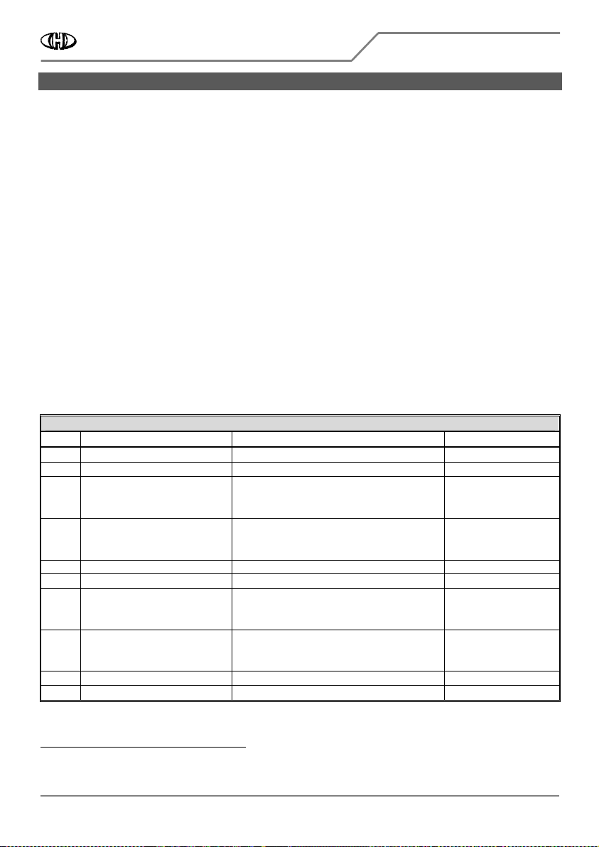
Table 2
Table 2 Table 2
Table 2 –
––
– Interface patch parameters
Interface patch parameters Interface patch parameters
Interface patch parameters
Parameter name
Parameter nameParameter name
Parameter name
Valid
Valid Valid
Valid
values
valuesvalues
values
Function
FunctionFunction
Function
CC
CC CC
CC
Nr.
Nr.Nr.
Nr.
Chapter
ChapterChapter
Chapter
VCO MIDI Notes Shift 0 ~ 84 Transposes MIDI Notes over the keyboard range 16 4.2.1
VCO Pitch Bend Range 0 ~ 12 Adjusts MIDI Pitch Bend maximal range 17 4.2.2
VCF Control Mode 0 ~ 2 Selects mode of VCF cutoff frequency control 18 4.2.3
VCF Key Follow
1
11
1
) 0 ~ 127 Range of VCF modulation by MIDI Note Nr. 19 4.2.4
VCF Velocity Amount
1
11
1
) 0 ~ 127 Range of VCF modulation by MIDI Notes velocity 20 4.2.5
VCF Chnl Aftertouch Amount
1
11
1
) 0 ~ 127 Range of VCF modulation by MIDI Channel Aftertouch 21 4.2.6
VCA Control Mode 0 ~ 2 Selects mode of VCA level control 22 4.2.7
VCA Key Follow
2
22
2
) 0 ~ 127 Range of VCA modulation by MIDI Note Nr. 23 4.2.8
VCA Velocity Amount
2
22
2
) 0 ~ 127 Range of VCA modulation by MIDI Notes velocity 24 4.2.9
VCA Chnl Aftertouch Amount
2
22
2
) 0 ~ 127 Range of VCA modulation by MIDI Channel Aftertouch 25 4.2.10
EG Retrigger Mode 0 ~ 2 Selects mode of EG control 26 4.2.11
EG Retrigger Rate
3
33
3
) 0 ~ 127 Selects rate of EG retrigger 27 4.2.12
Indicator Mode 0 ~ 3 Selects mode of interface’s LED indicator 28 4.2.13
1
11
1
) The parameter is not active in VCF Control Mode “Controller“ (VCF Control Mode = 2)
2
22
2
) The parameter is not active in VCA Control Mode “Controller“ (VCA Control Mode = 2)
3
33
3
) The parameter is not active in EG Retrigger Mode “Off“ (EG Retrigger Mode = 0)
Vermona Synthesizer MIDI Interface
Vermona Synthesizer MIDI InterfaceVermona Synthesizer MIDI Interface
Vermona Synthesizer MIDI Interface
VS
VS VS
VS-
--
-MIDI
MIDIMIDI
MIDI Owner‘s
Owner‘s Owner‘s
Owner‘s Manual
Manual Manual
Manual
8
88
8-
--
-434 / v. 2.00
434 / v. 2.00434 / v. 2.00
434 / v. 2.00
Copyright © 2022 CHD Elektroservis. All rights reserved.
No part of this publication may be reproduced in any form without the written permission of CHD Elektroservis.
7
7
7
7
Fig. 5
Fig. 5 Fig. 5
Fig. 5 –
––
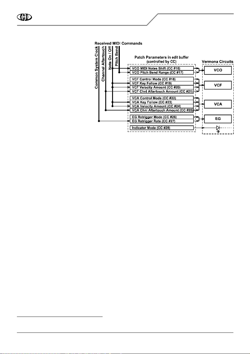
– Function of the interface patch parameters
Function of the interface patch parameters Function of the interface patch parameters
Function of the interface patch parameters
The patch parameters are loaded
from the interface memory to the
edit buffer (see fig. 4) and they
control the interface's functions from
here
6
66
6
. Values of all interface patch
parameters in edit buffer can be
modified by MIDI CCs (see chapter
5.1.2.2) - it is possible to change
them in a real time during playing the
instrument (see fig. 5). These
changes are temporary only. lf
necessary, new setting of the
parameters can be stored in an user
patch memory - up to 32 interface
patch parameters settings can be
stored (see MIDI SysEx
Communication manual). These
settings are recalled from the memory by Program Change standard MIDI command (see chapter 5.1.5).
4.2.1
4.2.14.2.1
4.2.1
VCO MIDI NOTES SHIFT (CC #16)
VCO MIDI NOTES SHIFT (CC #16)VCO MIDI NOTES SHIFT (CC #16)
VCO MIDI NOTES SHIFT (CC #16)
The parameter adjusts assignment of received MIDI Note numbers to the instrument keys. The parameter value
specifies exactly the number of MIDI Note which is assigned to the lowest key of the instrument’s keyboard. It
can be changed by MIDI CC Nr. 16 - see chapter 5.1.2.2.
The parameter value can be from 0 to 84. If value 0 is set, the lowest key on the keyboard corresponds to MIDI
Note Nr. 0 and the highest key corresponds to MIDI Note Nr. 43. If value 1 of the parameter is set, the lowest
key on the keyboard corresponds to MIDI Note Nr. 1 and the highest key corresponds to MIDI Note Nr. 44, etc.
up to value 84 of the parameter when the lowest key of the keyboard corresponds to MIDI Note Nr. 84 and the
highest key corresponds to MIDI Note Nr. 127. See fig. 6 on next page for more details.
4.2.2
4.2.24.2.2
4.2.2
VCO
VCO VCO
VCO PITCH BEND RANGE (CC #17)
PITCH BEND RANGE (CC #17)PITCH BEND RANGE (CC #17)
PITCH BEND RANGE (CC #17)
This parameter is active only for Pitch Bend MIDI command. It doesn't work with instrument's PITCH wheel
control element!
The parameter adjusts maximal allowed VCO’s pitch bending for full range of MIDI Pitch Bend. It can be
changed by MIDI CC Nr. 17 - see chapter 5.1.2.2.
The parameter value is from 0 to 12. The 0 value switches the pitch bend off – the Pitch Bend MIDI command is
ignored. The values of 1 to 12 are equal to bending the pitch in semitones. Bending up to ±1 octave is available
thus.
Remark:
Remark:Remark:
Remark:
The detune range of the VCO upwards can be limited for the highest octave and detune range higher than
approximately 4 semitones. This limitation is caused by the construction of the Vermona Synthesizer and it cannot be removed.
4.2.3
4.2.34.2.3
4.2.3
VCF CONTROL MODE (CC #18)
VCF CONTROL MODE (CC #18)VCF CONTROL MODE (CC #18)
VCF CONTROL MODE (CC #18)
The parameter selects method of the instrument’s VCF control. It can be changed by MIDI CC Nr. 18 - see
chapter 5.1.2.2.
The parameter value is 0 to 2. Three control modes are available thus:
6
During the interface reset, neutral values of the parameters are loaded into the edit buffer so that the interface doesn't affect the instrument.

Vermona Synthesizer MIDI Interface
Vermona Synthesizer MIDI InterfaceVermona Synthesizer MIDI Interface
Vermona Synthesizer MIDI Interface
VS
VS VS
VS-
--
-MIDI
MIDIMIDI
MIDI Owner‘s
Owner‘s Owner‘s
Owner‘s Manual
Manual Manual
Manual
8
88
8-
--
-434 / v. 2.00
434 / v. 2.00434 / v. 2.00
434 / v. 2.00
Copyright © 2022 CHD Elektroservis. All rights reserved.
No part of this publication may be reproduced in any form without the written permission of CHD Elektroservis.
8
8
8
8
Fig. 6
Fig. 6 Fig. 6
Fig. 6 –
––
– VCO MIDI Notes Shift parameter
VCO MIDI Notes Shift parameter VCO MIDI Notes Shift parameter
VCO MIDI Notes Shift parameter
• 0
0 0
0 Æ
ÆÆ
Æ EG:
EG: EG:
EG: Standard way of VCF control
where the instrument’s own
envelope generator (EG) is used for
the VCF control. The VCF cutoff
frequency is simultaneously
controlled by the ”Note-On +
Velocity” and ”Channel Aftertouch“
MIDI commands accordingly to
settings of the other VCF
parameters
7
77
7
.
• 1
1 1
1 Æ
ÆÆ
Æ GATE:
GATE: GATE:
GATE: Internal envelope
generator (EG) of the instrument is
disabled and VCF is controlled by the
square gate signal (equivalent of EG
setting: ATTACK = 0, DECAY = 0,
SUSTAIN = max., RELEASE = 0). The
VCF cutoff frequency is still
controlled by the ”Note-On +
Velocity” and ”Channel Aftertouch“
MIDI commands accordingly to
settings of the other VCF
parameters
7
77
7
.
• 2
2 2
2 Æ
ÆÆ
Æ CC:
CC: CC:
CC: VCF is controlled by one
MIDI CC selected by the global
parameter ”VCF CC Nr.“ (see chapter
4.1.2). In this case, the VCF cutoff
frequency is controlled by the values
of selected CC only. The “Note-On”
and “Channel Aftertouch“ MIDI
commands and the other VCF
parameters
7
7 7
7
do not affect the VCF
modulation – they are ignored.
This working mode can be used for
creation of special sound effects etc.
4.2.4
4.2.44.2.4
4.2.4
VCF KEY FOLLOW (CC #19)
VCF KEY FOLLOW (CC #19)VCF KEY FOLLOW (CC #19)
VCF KEY FOLLOW (CC #19)
The parameter sets affecting level of
the instrument’s VCF cutoff frequency
by position of key on the MIDI
keyboard (i.e. in dependence on tone
height). It can be changed by MIDI CC
Nr. 19 - see chapter 5.1.2.2.
The parameter value is 0 to 127. If the
value is equal to 64, the VCF remains
unaffected by the key position. For the
7
I.e. VCF Key Follow, VCF Velocity Amount and VCF Channel Aftertouc h parameters.

Vermona Synthesizer MIDI Interface
Vermona Synthesizer MIDI InterfaceVermona Synthesizer MIDI Interface
Vermona Synthesizer MIDI Interface
VS
VS VS
VS-
--
-MIDI
MIDIMIDI
MIDI Owner‘s
Owner‘s Owner‘s
Owner‘s Manual
Manual Manual
Manual
8
88
8-
--
-434 / v. 2.00
434 / v. 2.00434 / v. 2.00
434 / v. 2.00
Copyright © 2022 CHD Elektroservis. All rights reserved.
No part of this publication may be reproduced in any form without the written permission of CHD Elektroservis.
9
9
9
9
parameter values from 65 to 127, the VCF cutoff frequency is increased proportionally to the MIDI note
number. For the values from 63 to 0, the VCF cutoff frequency is decreased proportionally to the MIDI note
number.
4.2.5
4.2.54.2.5
4.2.5
VCF VELOCITY AMOUNT (CC #20)
VCF VELOCITY AMOUNT (CC #20)VCF VELOCITY AMOUNT (CC #20)
VCF VELOCITY AMOUNT (CC #20)
The parameter sets the modulation amount of the VCF cutoff frequency by MIDI Note Velocity. It can be
changed by MIDI CC Nr. 20 - see chapter 5.1.2.2.
The parameter value is 0 to 127. For 0 value, the VCF isn’t affected by the Note Velocity data, value equal to 127
provides maximal modulation level.
4.2.6
4.2.64.2.6
4.2.6
VCF CHNL AFTERTOUCH AMOUNT (CC #21)
VCF CHNL AFTERTOUCH AMOUNT (CC #21)VCF CHNL AFTERTOUCH AMOUNT (CC #21)
VCF CHNL AFTERTOUCH AMOUNT (CC #21)
The parameter sets the modulation amount of the VCF cutoff frequency by Channel Aftertouch MIDI command.
It can be changed by MIDI CC Nr. 21 - see chapter 5.1.2.2.
The parameter value is 0 to 127. For 0 value, VCF isn’t affected by the Channel Aftertouch MIDI command, value
equal to 127 provides maximal modulation level.
4.2.7
4.2.74.2.7
4.2.7
VCA CONTROL MODE (CC #22)
VCA CONTROL MODE (CC #22)VCA CONTROL MODE (CC #22)
VCA CONTROL MODE (CC #22)
The parameter selects method of the instrument’s VCA control. It can be changed by MIDI CC Nr. 22 - see
chapter 5.1.2.2.
The parameter value is 0 to 2. Three control modes are available thus:
• 0
0 0
0 Æ
ÆÆ
Æ EG:
EG: EG:
EG: Standard way of VCA control where the instrument’s own envelope generator (EG) is used for the
VCA control. The VCA level is simultaneously controlled by the ”Note-On + Velocity” and ”Channel
Aftertouch“ MIDI commands accordingly to settings of the other VCA parameters
8
88
8
.
• 1
1 1
1 Æ
ÆÆ
Æ GATE:
GATE: GATE:
GATE: Internal envelope generator (EG) of the instrument is disabled and VCA is controlled by the square
gate signal (equivalent of EG setting: ATTACK = 0, DECAY = 0, SUSTAIN = max., RELEASE = 0). The VCA level is
still controlled by the ”Note-On + Velocity” and ”Channel Aftertouch“ MIDI commands accordingly to settings
of the other VCA parameters
8
88
8
.
• 2
2 2
2 Æ
ÆÆ
Æ CC:
CC: CC:
CC: VCA is controlled by one MIDI CC selected by the global parameter ”VCA CC Nr.“ (see chapter 4.1.3).
In this case, the VCA level is controlled by the values of selected CC only. The “Note-On” and “Channel
Aftertouch“ MIDI commands and the other VCF parameters
8
8 8
8
do not affect the VCA modulation – they are
ignored.
4.2.8
4.2.84.2.8
4.2.8
VCA KEY FOLLOW (CC #23)
VCA KEY FOLLOW (CC #23)VCA KEY FOLLOW (CC #23)
VCA KEY FOLLOW (CC #23)
The parameter sets affecting level of the instrument’s VCA level by position of key on the MIDI keyboard (i.e. in
dependence on tone height). It can be changed by MIDI CC Nr. 23 - see chapter 5.1.2.2.
The parameter value is 0 to 127. If the value is equal to 64, the VCA remains unaffected by the key position. For
the parameter values from 65 to 127, the VCA level is increased proportionally to the MIDI note number. For
the values from 63 to 0, the VCA level is decreased proportionally to the MIDI note number.
4.2.9
4.2.94.2.9
4.2.9
VCA VELOCITY AMOUNT (CC #24)
VCA VELOCITY AMOUNT (CC #24)VCA VELOCITY AMOUNT (CC #24)
VCA VELOCITY AMOUNT (CC #24)
The parameter sets the modulation amount of the VCA level by MIDI Note Velocity. It can be changed by MIDI
CC Nr. 24 - see chapter 5.1.2.2.
8
I.e. VCA Key Follow, VCA Velocity Amount and VCA Channel Aftertouch parameters.
Vermona Synthesizer MIDI Interface
Vermona Synthesizer MIDI InterfaceVermona Synthesizer MIDI Interface
Vermona Synthesizer MIDI Interface
VS
VS VS
VS-
--
-MIDI
MIDIMIDI
MIDI Owner‘s
Owner‘s Owner‘s
Owner‘s Manual
Manual Manual
Manual
8
88
8-
--
-434 / v. 2.00
434 / v. 2.00434 / v. 2.00
434 / v. 2.00
Copyright © 2022 CHD Elektroservis. All rights reserved.
No part of this publication may be reproduced in any form without the written permission of CHD Elektroservis.
10
1010
10
The parameter value is 0 to 127. For 0 value, the VCA isn’t affected by the Note Velocity data, value equal to
127 provides maximal modulation level.
4.2.10
4.2.104.2.10
4.2.10
VCA CHNL AFTERTOUCH AMOUNT (CC #25)
VCA CHNL AFTERTOUCH AMOUNT (CC #25)VCA CHNL AFTERTOUCH AMOUNT (CC #25)
VCA CHNL AFTERTOUCH AMOUNT (CC #25)
The parameter sets the modulation amount of the VCF cutoff frequency by Channel Aftertouch MIDI command.
It can be changed by MIDI CC Nr. 25 - see chapter 5.1.2.2.
The parameter value is 0 to 127. For 0 value, VCA isn’t affected by the Channel Aftertouch MIDI command,
value equal to 127 provides maximal modulation level.
4.2.11
4.2.114.2.11
4.2.11
EG RETRIGGER MODE (CC #26)
EG RETRIGGER MODE (CC #26)EG RETRIGGER MODE (CC #26)
EG RETRIGGER MODE (CC #26)
The parameter enables / disables periodical retriggering of the instrument’s envelope generator (EG) during a
MIDI Note is active. It can be changed by MIDI CC Nr. 26 - see chapter 5.1.2.2.
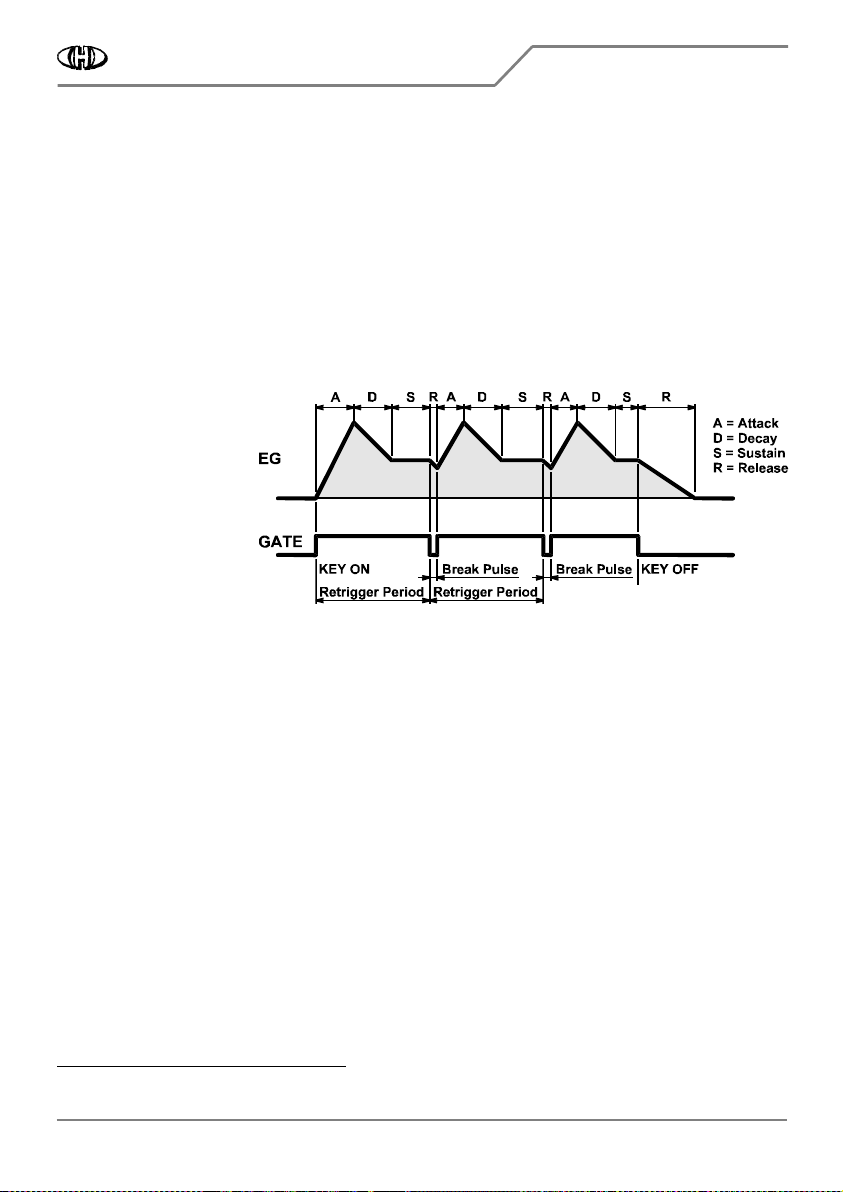
Fig. 7
Fig. 7 Fig. 7
Fig. 7 –
––
– EG Retrigger
EG Retrigger EG Retrigger
EG Retrigger
The parameter value is 0 to
2. Three retriggering modes
are available thus:
• 0
0 0
0 Æ
ÆÆ
Æ OFF:
OFF: OFF:
OFF: The retriggering
is disabled - the
instrument’s envelope
generator (EG) works
standard way.
• 1
1 1
1 Æ
ÆÆ
Æ FIXED:
FIXED: FIXED:
FIXED: Envelope
generator (EG) of the
instrument is periodically
retriggered with fixed period adjusted by the “EG Retrigger Rate” patch parameter (see table 7).
• 2
2 2
2 Æ
ÆÆ
Æ MIDI:
MIDI: MIDI:
MIDI: Envelope generator (EG) of the instrument is periodically retriggered with period derived from
MIDI Clock
9
99
9
in dependence on the “EG Retrigger Rate” patch parameter (see table 7).
Remark:
Remark:Remark:
Remark: The parameter is ignored (it is always set “Off“) if the Legato style play (CC #68) is on – see chapter
5.1.2.1.
4.2.12
4.2.124.2.12
4.2.12
EG RETRIGGER RATE (CC #27)
EG RETRIGGER RATE (CC #27)EG RETRIGGER RATE (CC #27)
EG RETRIGGER RATE (CC #27)
The parameter sets rate of instrument’s envelope generator retrigger if enabled by the “EG Retrigger Mode”
patch parameter. It can be changed by MIDI CC Nr. 27 - see chapter 5.1.2.2 and table 7.
4.2.13
4.2.134.2.13
4.2.13
INDICATOR MODE (CC #28)
INDICATOR MODE (CC #28)INDICATOR MODE (CC #28)
INDICATOR MODE (CC #28)
The parameter selects function of yellow LED indicator of the interface. It can be changed by MIDI CC Nr. 28 -
see chapter 5.1.2.2.
The parameter value is 0 to 3. Four modes of indication are available thus:
• 0
0 0
0 Æ
ÆÆ
Æ Off:
Off: Off:
Off: The indicator is off – the LED lights in red continuously.
• 1
1 1
1 Æ
ÆÆ
Æ MIDI EVENT:
MIDI EVENT: MIDI EVENT:
MIDI EVENT: The LED indicates incoming MIDI events by short blinking.
• 2
2 2
2 Æ
ÆÆ
Æ G
G G
GATE:
ATE:ATE:
ATE: The LED indicator copies status of the Gate signal.
• 3
3 3
3 Æ
ÆÆ
Æ RETRIGGER RATE:
RETRIGGER RATE: RETRIGGER RATE:
RETRIGGER RATE: The LED indicator blinks in the tempo of the envelope generator (EG) retriggering.
9
Transmitting of MIDI Clock must be enabled on your DAW.
Vermona Synthesizer MIDI Interface
Vermona Synthesizer MIDI InterfaceVermona Synthesizer MIDI Interface
Vermona Synthesizer MIDI Interface
VS
VS VS
VS-
--
-MIDI
MIDIMIDI
MIDI Owner‘s
Owner‘s Owner‘s
Owner‘s Manual
Manual Manual
Manual
8
88
8-
--
-434 / v. 2.00
434 / v. 2.00434 / v. 2.00
434 / v. 2.00
Copyright © 2022 CHD Elektroservis. All rights reserved.
No part of this publication may be reproduced in any form without the written permission of CHD Elektroservis.
11
1111
11
5
55
5
MIDI IMPLEMENTATION
MIDI IMPLEMENTATIONMIDI IMPLEMENTATION
MIDI IMPLEMENTATION
VS-MIDI interface uses all available MIDI communication methods – Channel Commands, Common System
Commands as well as System Exclusive messages
10
1010
10
for experts.
5.1
5.15.1
5.1
CHANNEL COMMANDS
CHANNEL COMMANDSCHANNEL COMMANDS
CHANNEL COMMANDS
The interface recognizes Note-Off, Note-On, Control Changes (CCs), Channel Aftertouch, Pitch Bend and
Program Change MIDI channel commands
11
1111
11
. All MIDI channel commands are received on the MIDI channel
defined by the MIDI CHANNEL global parameter (see chapter 4.1.1).
5.1.1
5.1.15.1.1
5.1.1
NOTE ON/OFF
NOTE ON/OFFNOTE ON/OFF
NOTE ON/OFF
The interface accepts Note-On and Note-Off commands in the range of max. 44 notes. Accepted range of the
MIDI note numbers are defined by the “MIDI Notes Shift” interface patch parameter (see chapter 4.2.1).
Although the Vermona Synthesizer is monophonic instrument, the interface memories last six active “Note-On”
commands. This feature is used when more keys are pressed on a master keyboard and the last pressed key is
then released. In this case, the interface switches back to the last previously pressed key. If there are already six
keys pressed and a next key is added, the newly added key replaces the key pressed at earliest (the last pressed
key has the highest priority).
5.1.2
5.1.25.1.2
5.1.2
MIDI CONTROL CHANGES (CCs)
MIDI CONTROL CHANGES (CCs)MIDI CONTROL CHANGES (CCs)
MIDI CONTROL CHANGES (CCs)
The interface recognizes standardized MIDI CCs (Nr. 64, 68 and 120 ~ 123) and some individually defined CCs
(Nr. 16 ~ 31) - see table 3 and description below.
Table 3
Table 3 Table 3
Table 3 –
––
– Acceptable CCs overview
Acceptable CCs overview Acceptable CCs overview
Acceptable CCs overview
CC Nr.
CC Nr.CC Nr.
CC Nr.
Name
NameName
Name
Function
FunctionFunction
Function
Valid value
Valid valueValid value
Valid value
16
2
) VCO MIDI Notes Shift (Transpose) Controls interface parameter 0 ~ 127 (see table 5)
17
2
) VCO Pitch Bend Range Controls interface parameter 0 ~ 127 (see table 6)
18
2
) VCF Control Mode Controls interface parameter
0 ~ 42 = EG
43 ~ 85 = Gate
86 ~ 127 = CC
19
2
) VCF Key Follow Controls interface parameter
0 ~ 63 = Decrement
64 = Off
64 ~ 127 = Increment
20
2
) VCF Velocity Amount Controls interface parameter 0 ~ 127
21
2
) VCF Chnl Aftertouch Amount Controls interface parameter 0 ~ 127
22
2
) VCA Control Mode Controls interface parameter
0 ~ 42 = EG
43 ~ 85 = Gate
86 ~ 127 = CC
23
2
) VCA Key Follow Controls interface parameter
0 ~ 63 = Decrement
64 = Off
64 ~ 127 = Increment
24
2
) VCA Velocity Amount Controls interface parameter 0 ~ 127
25
2
) VCA Chnl Aftertouch Amount Controls interface parameter 0 ~ 127
10
Please see stand-alone MIDI SysEx Communication manual for details.
11
So-called Running Status mode of MIDI communication is fully kept for all channel commands.
Vermona Synthesizer MIDI Interface
Vermona Synthesizer MIDI InterfaceVermona Synthesizer MIDI Interface
Vermona Synthesizer MIDI Interface
VS
VS VS
VS-
--
-MIDI
MIDIMIDI
MIDI Owner‘s
Owner‘s Owner‘s
Owner‘s Manual
Manual Manual
Manual
8
88
8-
--
-434 / v. 2.00
434 / v. 2.00434 / v. 2.00
434 / v. 2.00
Copyright © 2022 CHD Elektroservis. All rights reserved.
No part of this publication may be reproduced in any form without the written permission of CHD Elektroservis.
12
1212
12
Table 3
Table 3 Table 3
Table 3 –
––
– Acceptable CCs overview
Acceptable CCs overview Acceptable CCs overview
Acceptable CCs overview -
--
- continue
continue continue
continue
CC Nr.
CC Nr.CC Nr.
CC Nr.
Name
NameName
Name
Function
FunctionFunction
Function
Valid value
Valid valueValid value
Valid value
26
2
) EG Retrigger Mode Controls interface parameter
0 ~ 42 = Off
43 ~ 85 = Fixed
86 ~ 127 = MIDI
27
2
) EG Retrigger Rate Controls interface parameter 0 ~ 127 (see table 7)
28
2
) Indicator Mode Controls interface parameter
0 ~ 31 = Off
32 ~ 63 = MIDI Event
64 ~ 95 = Gate
96 ~ 127 = Retrig Rate
64
1
) Hold Standard MIDI function 0 ~ 63 = Off
64 ~ 127 = On
68
1
) Legato Standard MIDI function 0 ~ 63 = Off
64 ~ 127 = On
120
1
) All Sound Off Standard MIDI function 0 = ASO
1 ~ 127 = none function
121
1
) Reset All Controllers Standard MIDI function 0 = RAC
1 ~ 127 = none function
123
1
) All Notes Off Standard MIDI function 0 = ANO
1 ~ 127 = none function
@ VCF
CC#
3
) VCF Direct Control Direct control of VCF cutoff frequency 0 ~ 127
@ VCA
CC#
3
) VCA Direct Control Direct control of VCA level 0 ~ 127
Remarks:
Remarks:Remarks:
Remarks:
1
) Standardized CCs (see chapter 5.1.2.1)
2
) CCs for setting of interface patch parameters (see chapter 5.1.2.2)
3
) User selectable CCs for VCF and VCA direct control (see chapters 4.1.2 and 4.1.3)
5.1.2.1
5.1.2.15.1.2.1
5.1.2.1
STANDARDIZED CONTROLLERS
STANDARDIZED CONTROLLERSSTANDARDIZED CONTROLLERS
STANDARDIZED CONTROLLERS
CC #64 : Hold
CC #64 : HoldCC #64 : Hold
CC #64 : Hold
The CC #64 works standard way: holds VCO and EG of the instrument active during the hold pedal is pressed.
Values from 64 to 127 are recognized as hold-on status, values from 0 to 63 as hold-off status.
Fig. 8
Fig. 8 Fig. 8
Fig. 8 –
––
– Legato
Legato Legato
Legato
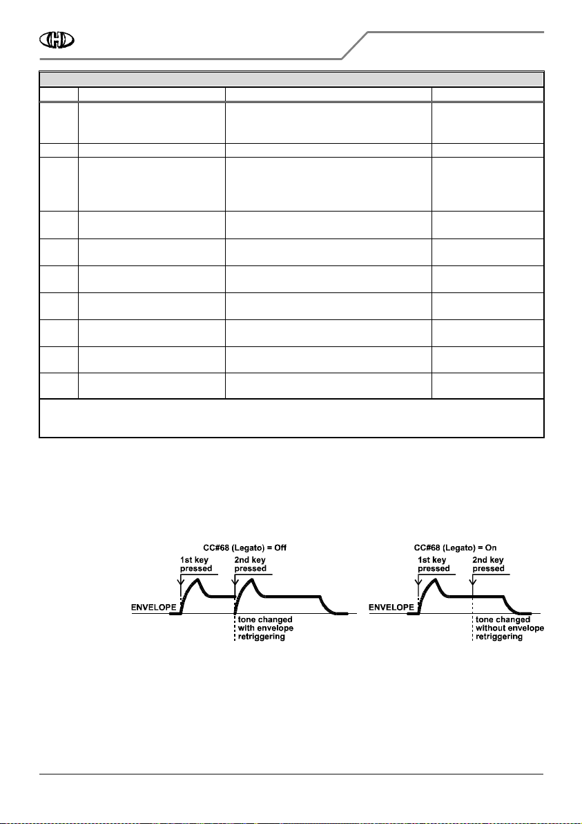
CC #68 : Legato
CC #68 : LegatoCC #68 : Legato
CC #68 : Legato
The controller
enables (values
from 64 to 127)
or disables
(values from 0 to
63) Legato style
play (see fig. 8).
If the Legato is off, the envelope generator (EG) is repeatedly launched every time when a new key is pressed
(i.e. a MIDI Note is received) before the previous key is not released yet. If the Legato is on, the newly pressed
key (i.e. newly received MIDI note) only changes frequency of the VCO and the envelope generator (EG)
remains unaffected.
Remark:
Remark:Remark:
Remark: If the Legato is on, the patch parameter “EG Retrigger Mode“ is ignored – it is always set “Off“. After
switching the Legato off, the original status of the “EG Retrigger Mode“ is recalled.

Vermona Synthesizer MIDI Interface
Vermona Synthesizer MIDI InterfaceVermona Synthesizer MIDI Interface
Vermona Synthesizer MIDI Interface
VS
VS VS
VS-
--
-MIDI
MIDIMIDI
MIDI Owner‘s
Owner‘s Owner‘s
Owner‘s Manual
Manual Manual
Manual
8
88
8-
--
-434 / v. 2.00
434 / v. 2.00434 / v. 2.00
434 / v. 2.00
Copyright © 2022 CHD Elektroservis. All rights reserved.
No part of this publication may be reproduced in any form without the written permission of CHD Elektroservis.
13
1313
13
CC #120 : All Sound Off (ASO)
CC #120 : All Sound Off (ASO)CC #120 : All Sound Off (ASO)
CC #120 : All Sound Off (ASO)
All active MIDI Notes are released immediately after reception of CC #120 (note that the value of the CC #120
must be always zero).
CC #121 : Reset All Controllers (RAC)
CC #121 : Reset All Controllers (RAC)CC #121 : Reset All Controllers (RAC)
CC #121 : Reset All Controllers (RAC)
Standardized MIDI CCs and MIDI Pitch Bend are set to their initial status after the CC #121 reception (note that
the value of the CC #121 must be always 0):
CC #64
CC #64CC #64
CC #64 (Hold)
Æ off (value 0)
CC #68
CC #68CC #68
CC #68 (Legato)
Æ off (value 0)
Pitch Bend
Pitch BendPitch Bend
Pitch Bend
Æ middle position (value 4096)
CC #123 : All Notes Off (A
CC #123 : All Notes Off (ACC #123 : All Notes Off (A
CC #123 : All Notes Off (ANO)
NO)NO)
NO)
All active MIDI Notes are released immediately after reception of CC #123 (note that the value of the CC #123
must be always zero).
5.1.2.2
5.1.2.25.1.2.2
5.1.2.2
CONTROLLERS FOR INTERFACE PATCH PARAMETERS EDITING
CONTROLLERS FOR INTERFACE PATCH PARAMETERS EDITINGCONTROLLERS FOR INTERFACE PATCH PARAMETERS EDITING
CONTROLLERS FOR INTERFACE PATCH PARAMETERS EDITING
This group of CCs adjusts values of the interface patch parameters in edit buffer – see fig. 4.
CC #16 : VCO MIDI Notes Shift (Transpose)
CC #16 : VCO MIDI Notes Shift (Transpose)CC #16 : VCO MIDI Notes Shift (Transpose)
CC #16 : VCO MIDI Notes Shift (Transpose)
Controls the parameter VCO MIDI Notes Shift (see chapter 4.2.1). Since the CC #16 value is 0 to 127 and the
parameter is 0 to 84 only, received value of the CC #16 is converted as shows table 5 in chapter 6.7.
CC #17 : VCO Pitch Bend Range
CC #17 : VCO Pitch Bend RangeCC #17 : VCO Pitch Bend Range
CC #17 : VCO Pitch Bend Range
Controls the parameter VCO Pitch Bend Range (see chapter 4.2.2). Since the CC #17 value is 0 to 127 and the
parameter is 0 to 12 only, received value of the CC #17 is converted as shows table 6 in chapter 6.7.
CC #18 : VCF Control Mode
CC #18 : VCF Control ModeCC #18 : VCF Control Mode
CC #18 : VCF Control Mode
Controls the parameter VCF Control Mode (see chapter 4.2.3). Since the CC #18 value is 0 to 127 and the
parameter is 0 to 2 only, received value of the CC #18 is converted: Values 0 ~ 42 correspond to the "EG" mode,
values 43 ~ 85 to the "GATE " mode and values 86 ~ 127 to the "CC " mode.
CC #19 : VCF Key Follow
CC #19 : VCF Key FollowCC #19 : VCF Key Follow
CC #19 : VCF Key Follow
Controls the parameter VCF Key Follow (see chapter 4.2.4). The CC#19 value from 0 to 127 corresponds to the
parameter value directly. Note that the CC#19 works as an offset controller - neutral value is 64.
CC #20 : VCF Velocity Amount
CC #20 : VCF Velocity AmountCC #20 : VCF Velocity Amount
CC #20 : VCF Velocity Amount
Controls the parameter VCF Velocity Amount (see chapter 4.2.5). The CC#20 value from 0 to 127 corresponds to
the parameter value directly.
CC #21 : VCF Chnl Aftertouch Amount
CC #21 : VCF Chnl Aftertouch AmountCC #21 : VCF Chnl Aftertouch Amount
CC #21 : VCF Chnl Aftertouch Amount
Controls the parameter VCF Channel (Mono) Aftertouch Amount (see chapter 4.2.6). The CC#21 value from 0 to
127 corresponds to the parameter value directly.
CC #22 : VCA Control Mode
CC #22 : VCA Control ModeCC #22 : VCA Control Mode
CC #22 : VCA Control Mode
Controls the parameter VCA Control Mode (see chapter 4.2.7). Since the CC #22 value is 0 to 127 and the
parameter is 0 to 2 only, received value of the CC #22 is converted: Values 0 ~ 42 correspond to the "EG" mode,
values 43 ~ 85 to the "GATE " mode and values 86 ~ 127 to the "CC " mode.

Vermona Synthesizer MIDI Interface
Vermona Synthesizer MIDI InterfaceVermona Synthesizer MIDI Interface
Vermona Synthesizer MIDI Interface
VS
VS VS
VS-
--
-MIDI
MIDIMIDI
MIDI Owner‘s
Owner‘s Owner‘s
Owner‘s Manual
Manual Manual
Manual
8
88
8-
--
-434 / v. 2.00
434 / v. 2.00434 / v. 2.00
434 / v. 2.00
Copyright © 2022 CHD Elektroservis. All rights reserved.
No part of this publication may be reproduced in any form without the written permission of CHD Elektroservis.
1
4
141
4
14
CC #23 : VCA Key Follow
CC #23 : VCA Key FollowCC #23 : VCA Key Follow
CC #23 : VCA Key Follow
Controls the parameter VCA Key Follow (see chapter 4.2.8). The CC#23 value from 0 to 127 corresponds to the
parameter value directly. Note that the CC#23 works as an offset controller - neutral value is 64.
CC #24 : VCA Velocity Amount
CC #24 : VCA Velocity AmountCC #24 : VCA Velocity Amount
CC #24 : VCA Velocity Amount
Controls the parameter VCA Velocity Amount (see chapter 4.2.9). The CC #24 value from 0 to 127 corresponds
to the parameter value directly.
CC #25 : VCA Chnl Aftertouch Amount
CC #25 : VCA Chnl Aftertouch AmountCC #25 : VCA Chnl Aftertouch Amount
CC #25 : VCA Chnl Aftertouch Amount
Controls the parameter VCA Channel (Mono) Aftertouch Amount (see chapter 4.2.10). The CC #25 value from 0
to 127 corresponds to the parameter value directly.
CC #26 : EG Retrigger Mode
CC #26 : EG Retrigger ModeCC #26 : EG Retrigger Mode
CC #26 : EG Retrigger Mode
Controls the parameter EG Retrigger Mode (see chapter 4.2.11). Since the CC #26 value is 0 to 127 and the
parameter is 0 to 2 only, received value of the CC #26 is converted: Values 0 ~ 42 correspond to the "OFF"
mode, values 43 ~ 85 to the "FIXED " mode and values 86 ~ 127 to the "MIDI " mode.
CC #27 : EG Retrigger Rate
CC #27 : EG Retrigger RateCC #27 : EG Retrigger Rate
CC #27 : EG Retrigger Rate
Controls the parameter EG Retrigger Rate (see chapter 4.2.12 and table 7). The CC#27 value from 0 to 127
corresponds to the parameter value directly.
CC #28 : Indicator Mode
CC #28 : Indicator ModeCC #28 : Indicator Mode
CC #28 : Indicator Mode
Controls the parameter Indicator Mode (see chapter 4.2.13). Since the CC #28 value is 0 to 127 and the
parameter is 0 to 3 only, received value of the CC #28 is converted: Values from 0 to 31 correspond to “OFF”
mode, 32 to 63 to “MIDI EVENT” mode, 64 to 95 to “GATE” mode and 96 to 127 to “RETRIG RATE” mode.
CC @ VCF CC Nr.: VCF Direct Control
CC @ VCF CC Nr.: VCF Direct ControlCC @ VCF CC Nr.: VCF Direct Control
CC @ VCF CC Nr.: VCF Direct Control
The CC selected by the VCF CC Nr. global parameter (see chapter 4.1.2) controls the instrument’s VCF directly if
the VCF Control Mode parameter is set to “CC” (see chapter 4.2.3).
CC @ VCA CC Nr.: VCA Direct Control
CC @ VCA CC Nr.: VCA Direct ControlCC @ VCA CC Nr.: VCA Direct Control
CC @ VCA CC Nr.: VCA Direct Control
The CC selected by the VCA CC Nr. global parameter (see chapter 4.1.3) controls the instrument’s VCA directly if
the VCA Control Mode parameter is set to “CC” (see chapter 4.2.7).
5.1.3
5.1.35.1.3
5.1.3
CHANNEL (MONO) AFTERTOUCH
CHANNEL (MONO) AFTERTOUCHCHANNEL (MONO) AFTERTOUCH
CHANNEL (MONO) AFTERTOUCH
The command can affect instrument’s VCF (cutoff frequency) accordingly to the VCF Chnl Aftertouch Amount
interface patch parameter setting (see chapter 4.2.6) and instrument’s VCA (level) accordingly to the VCA Chnl
Aftertouch Amount interface patch parameter setting (see chapter 4.2.10)
5.1.4
5.1.45.1.4
5.1.4
PITCH BEND
PITCH BENDPITCH BEND
PITCH BEND
The command has standard function – it controls instrument’s VCO tone bending accordingly to the VCO Pitch
Bend Range interface patch parameter setting (see chapter 4.2.2).
5.1.5
5.1.55.1.5
5.1.5
PROGRAM CHANGE
PROGRAM CHANGEPROGRAM CHANGE
PROGRAM CHANGE
The command switches the user patches of the interface (see chapter 4.2). Only program numbers from 0 to 31
are accepted. They conforms to interface patches 1 to 32 (see fig. 4). Program numbers from 32 to 127 are
ignored by the interface.
Vermona Synthesizer MIDI Interface
Vermona Synthesizer MIDI InterfaceVermona Synthesizer MIDI Interface
Vermona Synthesizer MIDI Interface
VS
VS VS
VS-
--
-MIDI
MIDIMIDI
MIDI Owner‘s
Owner‘s Owner‘s
Owner‘s Manual
Manual Manual
Manual
8
88
8-
--
-434 / v. 2.00
434 / v. 2.00434 / v. 2.00
434 / v. 2.00
Copyright © 2022 CHD Elektroservis. All rights reserved.
No part of this publication may be reproduced in any form without the written permission of CHD Elektroservis.
15
1515
15
Always when an acceptable Program Change MIDI command is received, the instrument is muted. When a next
MIDI command is then received, the interface starts to work accordingly to the parameters of newly selected
patch.
5.2
5.25.2
5.2
COMMON SYSTEM COMMANDS
COMMON SYSTEM COMMANDSCOMMON SYSTEM COMMANDS
COMMON SYSTEM COMMANDS
5.2.1
5.2.15.2.1
5.2.1
CLOCK
CLOCKCLOCK
CLOCK
The MIDI Clock system command can be used for synchronization of the envelope generator (EG) retrigger if
this function is enabled (see chapter 4.2.11).
Remark:
Remark:Remark:
Remark: The retrigger can work irregularly (some clock pulses will be omitted) if the MIDI tempo is extremely
high and value of the “EG Retrigger Rate” is near to maximum
12
1212
12
.
5.2.2
5.2.25.2.2
5.2.2
RESET
RESETRESET
RESET
When the Reset MIDI system command is received, the interface is forced to the reset status (the same as
when the instrument is switched on – see chapter 3.1).
5.3
5.35.3
5.3
SYSTEM EXCLUSIVE MESSAGES
SYSTEM EXCLUSIVE MESSAGESSYSTEM EXCLUSIVE MESSAGES
SYSTEM EXCLUSIVE MESSAGES
5.3.1
5.3.15.3.1
5.3.1
STRUCTURE OF SYSEX COMMUNICATION
STRUCTURE OF SYSEX COMMUNICATIONSTRUCTURE OF SYSEX COMMUNICATION
STRUCTURE OF SYSEX COMMUNICATION
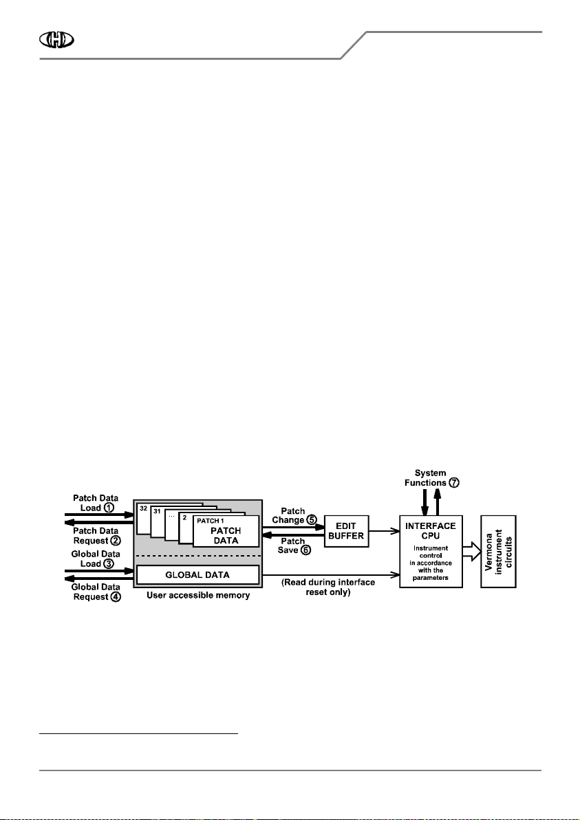
The MIDI System Exclusive communication (see fig. 9) enables many operations:
• It enables to rewrite content of any individual patch
①
in interface memory as well as content of global
parameters bank
③
. The content of any individual patch
②
or global bank
④
can also be read from the
interface on demand.
• Actual active patch can be changed
⑤
or overwritten with data from the edit buffer
⑥
.
• System functions
⑦
allow to process some special commands.
Fig. 9
Fig. 9 Fig. 9
Fig. 9 –
––
– Structure of System Exclusive communication
Structure of System Exclusive communication Structure of System Exclusive communication
Structure of System Exclusive communication
Please see the MIDI SysEx Communication manual for detailed description of the SysEx messages structure. The
manual is available at our web site (“Support → Manuals & Support Software” page).
12
See chapter 6.1 for details.

Vermona Synthesizer MIDI Interface
Vermona Synthesizer MIDI InterfaceVermona Synthesizer MIDI Interface
Vermona Synthesizer MIDI Interface
VS
VS VS
VS-
--
-MIDI
MIDIMIDI
MIDI Owner‘s
Owner‘s Owner‘s
Owner‘s Manual
Manual Manual
Manual
8
88
8-
--
-434 / v. 2.00
434 / v. 2.00434 / v. 2.00
434 / v. 2.00
Copyright © 2022 CHD Elektroservis. All rights reserved.
No part of this publication may be reproduced in any form without the written permission of CHD Elektroservis.
16
1616
16
5.3.2
5.3.25.3.2
5.3.2
SUPPORT FOR SYSEX MESSAGES CREATION
SUPPORT FOR SYSEX MESSAGES CREATIONSUPPORT FOR SYSEX MESSAGES CREATION
SUPPORT FOR SYSEX MESSAGES CREATION
As a support for the users we have made the SysEx Messages Generator software utility (see fig. 10) to create
MIDI System Exclusive messages to control the interface. All necessary SysEx messages can be created with this
generator without difficult calculating of binary or hexadecimal numbers. The SysEx Messages Generator utility
is available at our web site (“Support → Manuals & Support Software” page). Detailed description how to use
the utility is available in the MIDI SysEx Communication manual.
Fig. 10
Fig. 10 Fig. 10
Fig. 10 –
––
– SysEx Messages Generator
SysEx Messages Generator SysEx Messages Generator
SysEx Messages Generator
If you create a SysEx message yourself, it is necessary to calculate the “Checksum” byte. It can be processed
very simply with the CHD Checksum Calculator (see fig. 11). This special software calculator with guide how to
use it is available at our web site (“Support → Generally Applicable Software → CHD Checksum Calculator”
page).
Fig. 11
Fig. 11 Fig. 11
Fig. 11 –
––
– Checksum calculator
Checksum calculator Checksum calculator
Checksum calculator
Vermona Synthesizer MIDI Interface
Vermona Synthesizer MIDI InterfaceVermona Synthesizer MIDI Interface
Vermona Synthesizer MIDI Interface
VS
VS VS
VS-
--
-MIDI
MIDIMIDI
MIDI Owner‘s
Owner‘s Owner‘s
Owner‘s Manual
Manual Manual
Manual
8
88
8-
--
-434 / v. 2.00
434 / v. 2.00434 / v. 2.00
434 / v. 2.00
Copyright © 2022 CHD Elektroservis. All rights reserved.
No part of this publication may be reproduced in any form without the written permission of CHD Elektroservis.
17
1717
17
6
66
6
APPENDICES
APPENDICESAPPENDICES
APPENDICES
6.1
6.16.1
6.1
LIMITATION OF THE INTERFACE OPERATION
LIMITATION OF THE INTERFACE OPERATIONLIMITATION OF THE INTERFACE OPERATION
LIMITATION OF THE INTERFACE OPERATION
• The instrument must be controlled only by own keyboard or only by MIDI Notes – do not press keys on the
Vermoana’s keyboard during the MIDI control. It causes that the instrument’s VCO sounds totally out of tune!
• Maximal possible range of the instrument's VCO is 3 1/2 octaves. It conforms to range of acceptable MIDI
Notes. So a limitation of instrument’s VCO detuning by Pitch Bend MIDI command can occur on notes near
the low and high ends of the range when the requested detuning is larger than the instrument’s VCO
capabilities.
• Maximal speed of EG Retrigger is limited by the hardware construction of the instrument. If MIDI clock
frequency used for synchronization is extremely fast, the EG can work irregularly (some break pulses might be
omitted) especially if very short arpeggio note length is set. In such case, adjustment of the Gate Interrupt
Duration system parameter can help (see chapter 6.4).
6.2
6.26.2
6.2
ERROR STATUS INDICATION
ERROR STATUS INDICATIONERROR STATUS INDICATION
ERROR STATUS INDICATION
If any fatal error occurs in the very exceptional case during the interface operation, the interface’s indication
LED blinks in yellow periodically. In this case, the interface must be reset to restore the operation – it is
necessary to turn the instrument off and then on after a while.
6.3
6.36.3
6.3
ERRORS CAUSED BY MIDI LOOP
ERRORS CAUSED BY MIDI LOOPERRORS CAUSED BY MIDI LOOP
ERRORS CAUSED BY MIDI LOOP
When the VS-MIDI interface is controlled by a sequencer (DAW) bi-directionally (connection with both MIDI
cables – see fig. 2) and the sequencer isn’t set correctly, communication loop might occur and the entire MIDI
system “freezes”. All MIDI data incoming from sequencer to the interface are transferred back to the sequencer
(THRU function) – this causes infinite cyclic transfer of the same MIDI data through the sequencer. To avoid this
situation, throughput of MIDI data from input to output must be turned off in the sequencer. This function is
usually called MIDI ECHO or MIDI THRU. Check the user manual of your Sequencer for that setting.
6.4
6.46.4
6.4
EG BREAK PULSE DURATION ADJUSTMENT
EG BREAK PULSE DURATION ADJUSTMENTEG BREAK PULSE DURATION ADJUSTMENT
EG BREAK PULSE DURATION ADJUSTMENT
The length of the break impulses is defined by the following formula:
EG BREAK PULSE DURATION = (PARAMETER VALUE + 2) / 2
EG BREAK PULSE DURATION = (PARAMETER VALUE + 2) / 2EG BREAK PULSE DURATION = (PARAMETER VALUE + 2) / 2
EG BREAK PULSE DURATION = (PARAMETER VALUE + 2) / 2 [in milliseconds]
The parameter values range is 0 - 58, corresponding to the length of the break impulses 1 ms - 30 ms. Default
value is 6 (e.g. impulse with the length of approx. 4 ms). It is suitable for the most situations, only in the
exceptional situations the value of the parameter can be adjusted to provide reliable reaction of the Vermona
Synthesizer EG circuits. (see fig. 5).
Remark:
Remark:Remark:
Remark: Duration of generated interrupt pulses need not be changed from the factory pre-defined setting in
most cases. Only if the instrument reacts unreliable (i.e. some pulses are omitted and the envelope generator
runs irregularly) it is necessary to adjust the duration of the pulses.
6.5
6.56.5
6.5
VCO CV CALIBRATION
VCO CV CALIBRATIONVCO CV CALIBRATION
VCO CV CALIBRATION
The calibration allows exact adjustment of interface’s D/A converter controlling the instrument’s VCO. Range of
the calibration is approx. ±100 cents, tuning step is 1, 5873 cent (see table 8).
Remark:
Remark:Remark:
Remark: The calibration need not be proceed in most cases. Only if tuning of instrument’s own keyboard and
external MIDI keyboard (DAW) doesn’t match, you can correct this by the D/A converter calibration.

Vermona Synthesizer MIDI Interface
Vermona Synthesizer MIDI InterfaceVermona Synthesizer MIDI Interface
Vermona Synthesizer MIDI Interface
VS
VS VS
VS-
--
-MIDI
MIDIMIDI
MIDI Owner‘s
Owner‘s Owner‘s
Owner‘s Manual
Manual Manual
Manual
8
88
8-
--
-434 / v. 2.00
434 / v. 2.00434 / v. 2.00
434 / v. 2.00
Copyright © 2022 CHD Elektroservis. All rights reserved.
No part of this publication may be reproduced in any form without the written permission of CHD Elektroservis.
18
1818
18
6.6
6.66.6
6.6
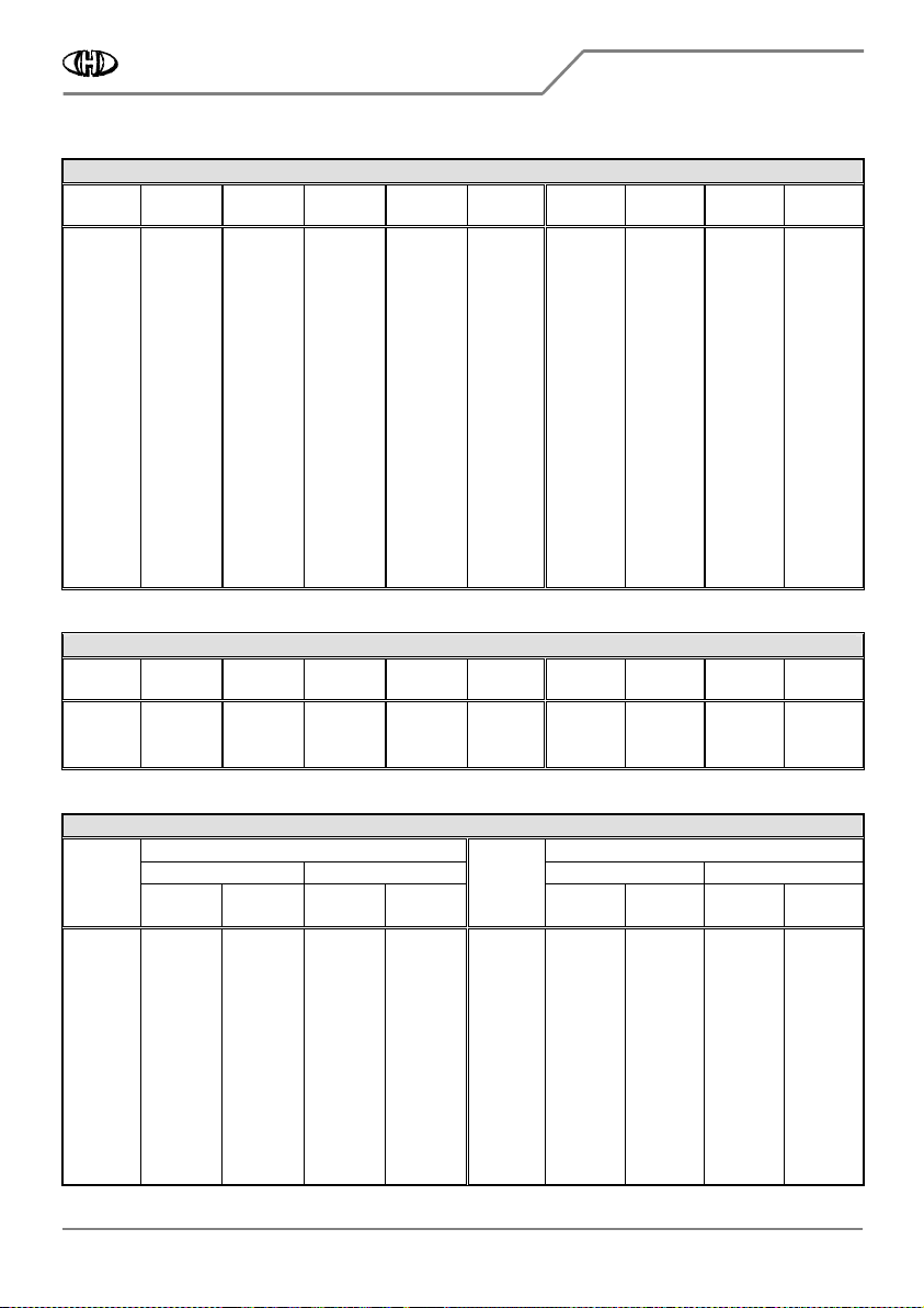
MIDI IMPLEMENTATION CHART
MIDI IMPLEMENTATION CHARTMIDI IMPLEMENTATION CHART
MIDI IMPLEMENTATION CHART
MIDI IMPLEMENTATION CHART
MIDI IMPLEMENTATION CHARTMIDI IMPLEMENTATION CHART
MIDI IMPLEMENTATION CHART
Device : VS
VSVS
VS-
--
-MIDI
MIDIMIDI
MIDI Date : 8 / 2022
8 / 20228 / 2022
8 / 2022
Model : 8
88
8-
--
-434
434434
434 Version : 2.0
.0.0
.0
Function Transmission Reception Remarks
Basic
Channel
Default
Changed
X
XX
X
X
XX
X
1~16
1~16
1
)
1
)
Mode Default
Messages
X
XX
X
X
XX
X
Mode 3
X
XX
X
Not Altered
2
)
Note Number X
XX
X
0~127
3
)
Velocity Note ON
Note OFF
X
XX
X
X
XX
X
O
OO
O
X
XX
X
After
Touch
Key's
Channel's
X
XX
X
X
XX
X
X
XX
X
O
OO
O
Pitch Bender X
XX
X
O
OO
O
Control Changes 1
16 to 28
64
68
120
121
@ VCF CC Nr.
@ VCA CC Nr.
X
XX
X
X
XX
X
X
XX
X
X
XX
X
X
XX
X
X
XX
X
X
XX
X
X
XX
X
O
OO
O
O
OO
O
O
OO
O
O
OO
O
O
OO
O
O
OO
O
O
OO
O
O
OO
O
Modulation
Own controllers – see description
Hold
Legato
All Sound Off
Reset All Controllers
Own controller
4
) – see description
Own controller
4
) – see description
Program Change X
XX
X
O
OO
O
Patch Change
System Exclusive O
OO
O
O
OO
O
See description
System
Common
Song Position
Song Select
Tune
X
XX
X
X
XX
X
X
XX
X
X
XX
X
X
XX
X
X
XX
X
System
Real Time
Clock
Command
X
XX
X
X
XX
X
O
OO
O
X
XX
X
Others Local ON/OFF
All Notes Off
Active Sensing
Reset
X
XX
X
X
XX
X
X
XX
X
X
XX
X
X
XX
X
O
OO
O
X
XX
X
O
OO
O
CC #123
Notes :
1
) Can be changed by user
2
) Six last received notes are memorized
3
) Position of 44 acceptable Note numbers depends on MIDI Notes Shift parameter setting
4
) Numbers of these CCs are user selectable
Mode 1 : OMNI ON, POLY
OMNI ON, POLYOMNI ON, POLY
OMNI ON, POLY
Mode 3 : OMNI OFF, POLY
OMNI OFF, POLYOMNI OFF, POLY
OMNI OFF, POLY
Mode 2 : OMNI ON, MONO
OMNI ON, MONOOMNI ON, MONO
OMNI ON, MONO
Mode 4 : O
OO
OMNI OFF, MONO
MNI OFF, MONOMNI OFF, MONO
MNI OFF, MONO
O
OO
O : Yes
X
XX
X : No
Vermona Synthesizer MIDI Interface
Vermona Synthesizer MIDI InterfaceVermona Synthesizer MIDI Interface
Vermona Synthesizer MIDI Interface
VS
VS VS
VS-
--
-MIDI
MIDIMIDI
MIDI Owner‘s
Owner‘s Owner‘s
Owner‘s Manual
Manual Manual
Manual
8
88
8-
--
-434 / v. 2.00
434 / v. 2.00434 / v. 2.00
434 / v. 2.00
Copyright © 2022 CHD Elektroservis. All rights reserved.
No part of this publication may be reproduced in any form without the written permission of CHD Elektroservis.
19
1919
19
6.7
6.76.7
6.7
CONVERSION TABLES
CONVERSION TABLESCONVERSION TABLES
CONVERSION TABLES
Table 5
Table 5 Table 5
Table 5 –
––
– Conversion of CC #16 value to “VCO MIDI NOTES SHIFT” parameter value
Conversion of CC #16 value to “VCO MIDI NOTES SHIFT” parameter value Conversion of CC #16 value to “VCO MIDI NOTES SHIFT” parameter value
Conversion of CC #16 value to “VCO MIDI NOTES SHIFT” parameter value
CC value
CC valueCC value
CC value
Param.
Param. Param.
Param.
value
valuevalue
value
CC value
CC valueCC value
CC value
Param.
Param. Param.
Param.
value
valuevalue
value
CC value
CC valueCC value
CC value
Param.
Param. Param.
Param.
value
valuevalue
value
CC value
CC valueCC value
CC value
Param.
Param. Param.
Param.
value
valuevalue
value
CC value
CC valueCC value
CC value
Param.
Param. Param.
Param.
value
valuevalue
value
0 ~ 1
2 ~ 3
4
5 ~ 6
7
8 ~ 9
10
11 ~ 12
13
14 ~ 15
16
17 ~ 18
19
20 ~ 21
22
23 ~ 24
25
0
1
2
3
4
5
6
7
8
9
10
11
12
13
14
15
16
26 ~ 27
28
29 ~ 30
31
32 ~ 33
34
35 ~ 36
37
38 ~ 39
40
41 ~ 42
43
44 ~ 45
46
47 ~48
49
50 ~ 51
17
18
19
20
21
22
23
24
25
26
27
28
29
30
31
32
33
52
53 ~ 54
55
56 ~ 57
58
59 ~ 60
61
62 ~ 63
64
65 ~ 66
67
68 ~ 69
70
71 ~ 72
73
74 ~ 75
76
34
35
36
37
38
39
40
41
42
43
44
45
46
47
48
49
50
77 ~ 78
79
80 ~ 81
82
83 ~ 84
85
86 ~ 87
88
89 ~ 90
91
62 ~ 93
94
95 ~ 96
97
98 ~ 99
100
101 ~ 102
51
52
53
54
55
56
57
58
59
60
61
62
63
64
65
66
67
103
104 ~ 105
106
107 ~ 108
109
110 ~ 111
112
113 ~ 114
115
116 ~ 117
118
119 ~ 120
121
122 ~ 123
124
125 ~ 126
127
68
69
70
71
72
73
74
75
76
77
78
79
80
81
82
83
84
Table 6
Table 6 Table 6
Table 6 –
––
– Conversion of CC #
Conversion of CC # Conversion of CC #
Conversion of CC #17 value t
17 value t17 value t
17 value to ”VCO PITCH BEND RANGE“ parameter value
o ”VCO PITCH BEND RANGE“ parameter valueo ”VCO PITCH BEND RANGE“ parameter value
o ”VCO PITCH BEND RANGE“ parameter value
CC value
CC valueCC value
CC value
Param.
Param. Param.
Param.
value
valuevalue
value
CC value
CC valueCC value
CC value
Param.
Param. Param.
Param.
value
valuevalue
value
CC value
CC valueCC value
CC value
Param.
Param. Param.
Param.
value
valuevalue
value
CC value
CC valueCC value
CC value
Param.
Param. Param.
Param.
value
valuevalue
value
CC value
CC valueCC value
CC value
Param.
Param. Param.
Param.
value
valuevalue
value
0 ~ 9
10 ~ 19
20 ~ 29
±0
±1
±2
30 ~ 39
40 ~ 49
50 ~ 59
±3
±4
±5
60 ~ 69
70 ~ 79
80 ~ 89
±6
±7
±8
90 ~ 99
100 ~ 109
110 ~ 119
±9
±10
±11
120 ~ 127 ±12
Table 7
Table 7 Table 7
Table 7 –
––
– Conversion of “EG RETRIGGER RATE“ parameter and CC #27 value to retrigger frequency / period
Conversion of “EG RETRIGGER RATE“ parameter and CC #27 value to retrigger frequency / period Conversion of “EG RETRIGGER RATE“ parameter and CC #27 value to retrigger frequency / period
Conversion of “EG RETRIGGER RATE“ parameter and CC #27 value to retrigger frequency / period
Mode (param.
Mode (param. Mode (param.
Mode (param. EG RETRIGGER
EG RETRIGGEREG RETRIGGER
EG RETRIGGER MODE)
MODE) MODE)
MODE)
Mode (param.
Mode (param. Mode (param.
Mode (param. EG
EG EG
EG RETRIGGER
RETRIGGERRETRIGGER
RETRIGGER MODE)
MODE) MODE)
MODE)
FIXED
FIXEDFIXED
FIXED
MIDI
MIDIMIDI
MIDI
FIXED
FIXEDFIXED
FIXED
MIDI
MIDIMIDI
MIDI
The
The The
The
param. or
param. or param. or
param. or
CC #27
CC #27 CC #27
CC #27
value
valuevalue
value
Freq.
Freq.Freq.
Freq.
[Hz]
[Hz][Hz]
[Hz]
Period
PeriodPeriod
Period
[sec]
[sec][sec]
[sec]
Period
PeriodPeriod
Period
[ticks]
[ticks][ticks]
[ticks]
Note
Note Note
Note
length
lengthlength
length
The
The The
The
param. or
param. or param. or
param. or
CC #27
CC #27 CC #27
CC #27
value
valuevalue
value
Freq.
Freq.Freq.
Freq.
[Hz]
[Hz][Hz]
[Hz]
Period
PeriodPeriod
Period
[sec]
[sec][sec]
[sec]
Period
PeriodPeriod
Period
[ticks]
[ticks][ticks]
[ticks]
Note
Note Note
Note
length
lengthlength
length
0
1
2
3
4
5
6
7
8
9
10
11
0,400
0,413
0,425
0,439
0,452
0,467
0,481
0,496
0,512
0,528
0,544
0,561
2,500
2,424
2,351
2,280
2,210
2,143
2,078
2,015
1,954
1,895
1,837
1,782
128
127
126
125
124
123
122
121
120
119
118
117
-
-
-
-
-
-
-
-
-
-
-
-
12
13
14
15
16
17
18
19
20
21
22
23
0,579
0,597
0,616
0,635
0,655
0,675
0,696
0,718
0,741
0,764
0,788
0,812
1,728
1,675
1,624
1,575
1,527
1,481
1,436
1,393
1,350
1,309
1,270
1,231
116
115
114
113
112
111
110
109
108
107
106
105
-
-
-
-
-
-
-
-
-
-
-
-
Vermona Synthesizer MIDI Interface
Vermona Synthesizer MIDI InterfaceVermona Synthesizer MIDI Interface
Vermona Synthesizer MIDI Interface
VS
VS VS
VS-
--
-MIDI
MIDIMIDI
MIDI Owner‘s
Owner‘s Owner‘s
Owner‘s Manual
Manual Manual
Manual
8
88
8-
--
-434 / v. 2.00
434 / v. 2.00434 / v. 2.00
434 / v. 2.00
Copyright © 2022 CHD Elektroservis. All rights reserved.
No part of this publication may be reproduced in any form without the written permission of CHD Elektroservis.
20
2020
20
Table 7
Table 7 Table 7
Table 7 –
––
– Conversion of “EG RETRIGGER RATE“ parameter and CC #27 value to retrigger frequency / period (continue)
Conversion of “EG RETRIGGER RATE“ parameter and CC #27 value to retrigger frequency / period (continue) Conversion of “EG RETRIGGER RATE“ parameter and CC #27 value to retrigger frequency / period (continue)
Conversion of “EG RETRIGGER RATE“ parameter and CC #27 value to retrigger frequency / period (continue)
Mode (param.
Mode (param. Mode (param.
Mode (param. EG RETRIGGER
EG RETRIGGEREG RETRIGGER
EG RETRIGGER MODE)
MODE) MODE)
MODE)
Mode (param.
Mode (param. Mode (param.
Mode (param. EG RETRIGGER
EG RETRIGGEREG RETRIGGER
EG RETRIGGER MODE)
MODE) MODE)
MODE)
FIXED
FIXEDFIXED
FIXED
MIDI
MIDIMIDI
MIDI
FIXED
FIXEDFIXED
FIXED
MIDI
MIDIMIDI
MIDI
The
The The
The
param.
param.param.
param. or
or or
or
CC #24
CC #24 CC #24
CC #24
value
valuevalue
value
Freq.
Freq.Freq.
Freq.
[Hz]
[Hz][Hz]
[Hz]
Period
PeriodPeriod
Period
[sec]
[sec][sec]
[sec]
Period
PeriodPeriod
Period
[ticks]
[ticks][ticks]
[ticks]
Note
Note Note
Note
length
lengthlength
length
The
The The
The
param. or
param. or param. or
param. or
CC #24
CC #24 CC #24
CC #24
value
valuevalue
value
Freq.
Freq.Freq.
Freq.
[Hz]
[Hz][Hz]
[Hz]
Period
PeriodPeriod
Period
[sec]
[sec][sec]
[sec]
Period
PeriodPeriod
Period
[ticks]
[ticks][ticks]
[ticks]
Note
Note Note
Note
length
lengthlength
length
24
25
26
27
28
29
30
31
32
3232
32
33
34
35
36
37
38
39
40
41
42
43
44
45
46
47
48
49
50
51
52
53
54
55
56
57
58
59
60
61
62
63
64
6464
64
65
66
67
0,838
0,864
0,891
0,919
0,947
0,977
1,008
1,040
1,072
1,106
1,140
1,176
1,212
1,250
1,289
1,330
1,372
1,414
1,459
1,504
1,552
1,600
1,650
1,702
1,754
1,810
1,866
1,925
1,984
2,047
2,112
2,176
2,245
2,315
2,387
2,463
2,538
2,618
2,699
2,786
2,874
2,963
3,053
3,150
1,194
1,158
1,123
1,089
1,056
1,024
0,992
0,962
0,933
0,905
0,877
0,851
0,825
0,800
0,776
0,752
0,729
0,707
0,686
0,665
0,645
0,625
0,606
0,588
0,570
0,553
0,536
0,520
0,504
0,489
0,474
0,460
0,446
0,432
0,419
0,406
0,394
0,382
0,371
0,359
0,348
0,338
0,328
0,318
104
103
102
101
100
99
98
97
96
9696
96
95
94
93
92
91
90
89
88
87
86
85
84
83
82
81
80
79
78
77
76
75
74
73
72
71
70
69
68
67
66
65
64
6464
64
63
62
61
-
-
-
-
-
-
-
-
1/1
1/11/1
1/1
-
-
-
-
-
-
-
-
-
-
-
-
-
-
-
-
-
-
-
-
-
-
-
-
-
-
-
-
-
-
-
1/1
1/11/1
1/1
3
33
3
-
-
-
68
69
70
71
72
73
74
75
76
77
78
79
80
8080
80
81
82
83
84
85
86
87
88
89
90
91
92
93
94
95
96
9696
96
97
98
99
100
101
102
103
104
104104
104
105
106
107
108
109
110
111
3,247
3,350
3,454
3,565
3,676
3,788
3,906
4,032
4,158
4,283
4,425
4,556
4,706
4,854
5,000
5,155
5,319
5,479
5,650
5,831
6,024
6,211
6,390
6,601
6,803
7,018
7,246
7,463
7,692
7,937
8,197
8,439
8,696
8,969
9,259
9,569
9,852
10,152
10,471
10,811
11,111
11,494
11,834
12,195
0,308
0,299
0,290
0,281
0,272
0,264
0,256
0,248
0,241
0,234
0,226
0,220
0,213
0,206
0,200
0,194
0,188
0,183
0,177
0,172
0,166
0,161
0,157
0,152
0,147
0,143
0,138
0,134
0,130
0,126
0,122
0,119
0,115
0,112
0,108
0,105
0,102
0,099
0,096
0,093
0,090
0,087
0,085
0,082
60
59
58
57
56
55
54
53
52
51
50
49
48
4848
48
47
46
45
44
43
42
41
40
39
38
37
36
35
34
33
32
3232
32
31
30
29
28
27
26
25
24
2424
24
23
22
21
20
19
18
17
-
-
-
-
-
-
-
-
-
-
-
-
1/2
1/21/2
1/2
-
-
-
-
-
-
-
-
-
-
-
-
-
-
-
1/2
1/21/2
1/2
3
33
3
-
-
-
-
-
-
-
1/4
1/41/4
1/4
-
-
-
-
-
-
-
Note:
Note:Note:
Note: The most used values for MIDI synchronization are marked in bold.
This manual suits for next models
1
Table of contents


