CNP INDUSTRIES PFA36SCG Installation guide
OCT06.0101
PFA42SCG
PFA36SCG
www.windcrestcnp.com
By CNP INDUSTRIES, INC.
All manuals and user guides at all-guides.com

All manuals and user guides at all-guides.com
PLEASE READ ENTIRE INSTRUCTIONS BEFORE PROCEEDING.
INSTALLATION MUST COMPLY WITH ALL LOCAL CODES.
IMPORTANT: Save these Instructions for the Local Electrical Inspector’s use.
INSTALLER: Please leave these Instructions with this unit for the owner.
OWNER: Please retain these instructions for future reference.
Safety Warning: Turn off power circuit at service panel and lock out panel, before wiring this appliance.
Requirement: 120 V AC, 60 Hz. 15 or 20 A Branch Circuit
APPROVED FOR RESIDENTIAL APPLIANCES
FOR RESIDENTIAL USE ONLY
READ AND SAVE THESE INSTRUCTIONS
Spanish page 3
English page 2
French page 20
9
2
All manuals and user guides at all-guides.com
Table of Contents
Installation Instruction..................................................................8
Before installing the hood......................................................................................5
Important safety Notice.................................................................4
Electrical requirements..........................................................................................5
Electrical & Installation requirements.......................................5Electrical & Installation requirements.......................................5Electrical & Installation requirements.......................................5
Preparation..............................................................................................................8
Part supplied...........................................................................................................6
List of Materials...............................................................................6
Description of the hood & Controls..........................................13
Part not supplied.....................................................................................................6
Dimension and clearances..........................................................7
Installation - Ductwork Calculation Sheet -..............................9
Electrical connection....................................................................10
List of Part and Accessories.....................................................19
Venting methods.....................................................................................................8
Controls: filter change indicator (metal filters)....................................................16
Controls: filter change indicator (carbon filters)..................................................15
Installation.......................................................................................11
Touch controls & features....................................................................................14
Cleaning.................................................................................................................17
Grease filter...........................................................................................................17
Replacing the light bulb........................................................................................17
Maintenance......................................................................................17
Trouble Shooting......................................................................18
www.windcrestcnp.com
3
All manuals and user guides at all-guides.com
Important safety Notice
CAUTION:
FOR GENERAL VENTILATING USE ONLY. DO NOT USE TO EXHAUST HAZARDOUS OR EXPLOSIVE MATERIALS
OR VAPORS.
WARNING
TO REDUCE THE RISK OF FIRE, ELECTRIC SHOCK, OR INJURY TO PERSONS, OBSERVE THE FOLLOWING:
A. Use this unit only in the manner intended by the manufacturer. If you have questions, contact the manufacturer.
B. Before servicing or cleaning the unit, switch power off at service panel and lock service panel disconnecting means to
prevent power from being switched on accidentally. When the service disconnecting means cannot be locked,
securely fasten a prominent warning device, such as a tag, to the service panel.
C. Installation Work and lectrical Wiring Must Be Done By Qualified Person(s) In Accordance With All Applicable Codes
& Standards, Including Fire-rated Construction.
D. Sufficient air is needed for proper combustion and exhausting of gases through the flue (chimney) of fuel burning
equipment to prevent back- drafting. Follow the heating equipment manufacturers guideline and safety standards such
as those published by the National Fire Protection Association (NFPA), the American Society for Heating, Refrigeration
and Air Conditioning ngineers (ASHRA ), and the local code authorities.
E. When cutting or drilling into wall or ceiling, do not damage electrical wiring and other hidden utilities.
F. Ducted systems must always be vented to the outdoors.
CAUTION:
To educe isk of fi e and to p ope ly exhaust ai , be su e to duct ai outside - do not vent exhaust ai into spaces
within walls, ceilings, attics, c awl spaces, o ga ages.
WARNING
TO REDUCE THE RISK OF FIRE, USE ONLY METAL DUCT WORK.
Install this hood in accordance with all requirements specified.
WARNING
To Reduce The Risk Of Fi e O Elect ic Shock, Do Not Use This Hood With Any Exte nal Solid State Speed
Cont ol Device.
WARNING
TO REDUCE THE RISK OF A RANGE TOP GREASE FIRE.
a) Never leave surface units unattended at high settings. Boilovers cause smoking and greasy spillovers that may ignite.
Heat oils slowly on low or medium settings.
b) Always turn hood ON when cooking at high heat or when flambeing food (i.e. Crepes Suzette, Cherries Jubilee,
Peppercorn Beef Flambe).
c) Clean ventilating fans frequently. Grease should not be allowed to accumulate on fan or filter.
d) Use proper pan size. Always use cookware appropriate for the size of the surface element.
WARNING
TO REDUCE THE RISK OF INJURY TO PERSONS, IN THE EVENT OF A RANGE TOP GREASE FIRE, OBSERVE THE
FOLLOWING:
a) SMOTH R FLAM S with a close-fitting lid, cookie sheet, or other metal tray, then turn off the gas burner or the electric
element. B CAR FUL TO PR V NT BURNS. If the flames do not go out immediately, VACUAT AND CALL TH
FIR D PARTM NT.
b) N V R PICK UP A FLAMING PAN - you may be burned.
c) DO NOT US WAT R, including wet dishcloths or towels - a violent steam explosion will result.
d) Use an extinguisher ONLY if:
1) You know you have a class ABC extinguisher, and you already know how to operate it.
2) The fire is small and contained in the area where it started.
3) The fire department is being called.
4) You can fight the fire with your back to an exit.
OPERATION
a. Always leave safety grills and filters in place. Without these components, operating blowers could catch onto hair,
fingers and loose clothing.
The manufacturer declines all responsibility in the event of failure to observe the instructions given here for installation,
maintenance and suitable use of the product. The manufacturer further declines all responsibility for injury due to
negligence and the warranty of the unit automatically expires due to improper maintenance.
* NOT : Please check our website for revisions before doing any custom work.
READ AND SAVE THESE INSTRUCTIONS
4
All manuals and user guides at all-guides.com
Electrical & Installation requirements
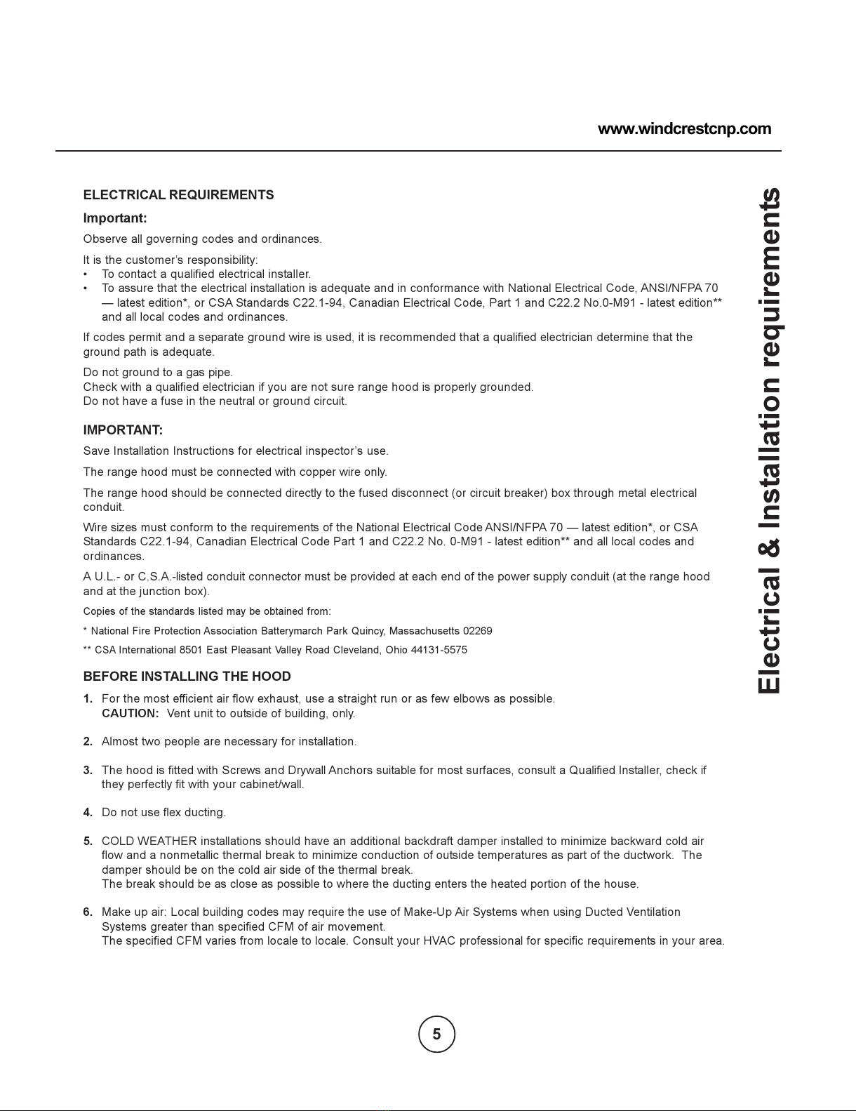
ELECTRICAL REQUIREMENTS
Important:
Observe all governing codes and ordinances.
It is the customers responsibility:
To contact a qualified electrical installer.
To assure that the electrical installation is adequate and in conformance with National lectrical Code, ANSI/NFPA 70
latest edition*, or CSA Standards C22.1-94, Canadian lectrical Code, Part 1 and C22.2 No.0-M91 - latest edition**
and all local codes and ordinances.
If codes permit and a separate ground wire is used, it is recommended that a qualified electrician determine that the
ground path is adequate.
Do not ground to a gas pipe.
Check with a qualified electrician if you are not sure range hood is properly grounded.
Do not have a fuse in the neutral or ground circuit.
IMPORTANT:
Save Installation Instructions for electrical inspectors use.
The range hood must be connected with copper wire only.
The range hood should be connected directly to the fused disconnect (or circuit breaker) box through metal electrical
conduit.
Wire sizes must conform to the requirements of the National lectrical Code ANSI/NFPA 70 latest edition*, or CSA
Standards C22.1-94, Canadian lectrical Code Part 1 and C22.2 No. 0-M91 - latest edition** and all local codes and
ordinances.
A U.L.- or C.S.A.-listed conduit connector must be provided at each end of the power supply conduit (at the range hood
and at the junction box).
Copies of the standards listed may be obtained from:
* National Fire Protection Association Batterymarch Park Quincy, assachusetts 02269
** CSA International 8501 East Pleasant Valley Road Cleveland, Ohio 44131-5575
BEFORE INSTALLING THE HOOD
1. For the most efficient air flow exhaust, use a straight run or as few elbows as possible.
CAUTION: Vent unit to outside of building, only.
2. Almost two people are necessary for installation.
3. The hood is fitted with Screws and Drywall Anchors suitable for most surfaces, consult a Qualified Installer, check if
they perfectly fit with your cabinet/wall.
4. Do not use flex ducting.
5. COLD W ATH R installations should have an additional backdraft damper installed to minimize backward cold air
flow and a nonmetallic thermal break to minimize conduction of outside temperatures as part of the ductwork. The
damper should be on the cold air side of the thermal break.
The break should be as close as possible to where the ducting enters the heated portion of the house.
6. Make up air: Local building codes may require the use of Make-Up Air Systems when using Ducted Ventilation
Systems greater than specified CFM of air movement.
The specified CFM varies from locale to locale. Consult your HVAC professional for specific requirements in your area.
www.windcrestcnp.com
5
All manuals and user guides at all-guides.com

List of Materials
PART SUPPLIED
PART NOT SUPPLIED
- Duct, conduit all tools required for installation
To be used only in the
- Glass canopy.
- Hood canopy assembly with blower.
- Duct Convers.
- Use Care and Installation Guide.
- Hardware Packet
46 screw 3.5x9.5 to assemble chimmey structure and to fix the duct convers under ceiling
4 washer 4x16 to assemble chimmey structure to ceiling
- Grease filters (2p.) and lamps (2p.), already installed.
- Chimmey structure.
4 anchors to assemble chimmey structure to ceiling
4 screw 5x50 to assemble chimmey structure to ceiling
includes: charcoal filter, charcoal filter support and fixing bracket, deflector
- Ductless Recirculating Kit
Ductless (Recirculating)version
- Warranty.
6
All manuals and user guides at all-guides.com
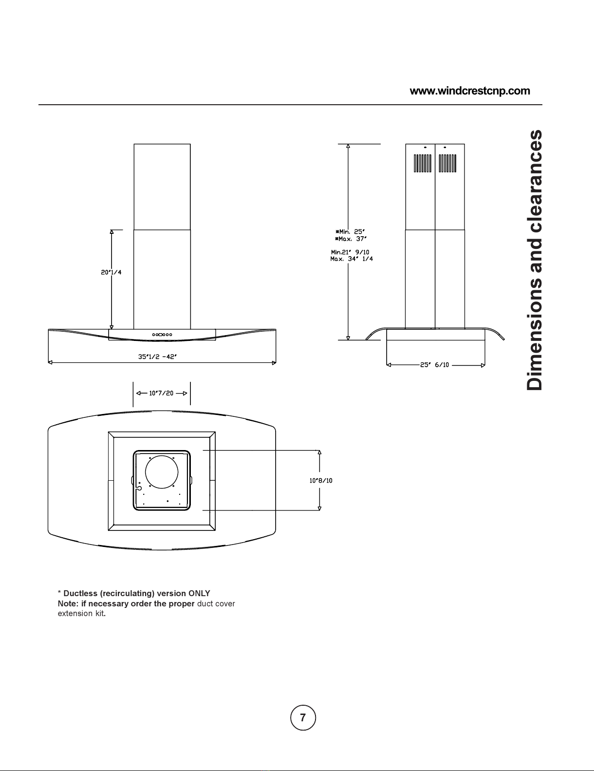
Dimensions and clearances
* Ductless ( eci culating) ve sion ONLY
Note: if necessa y o de the p ope duct cover
extension kit.
www.windcrestcnp.com
7
All manuals and user guides at all-guides.com
Installation Instructions
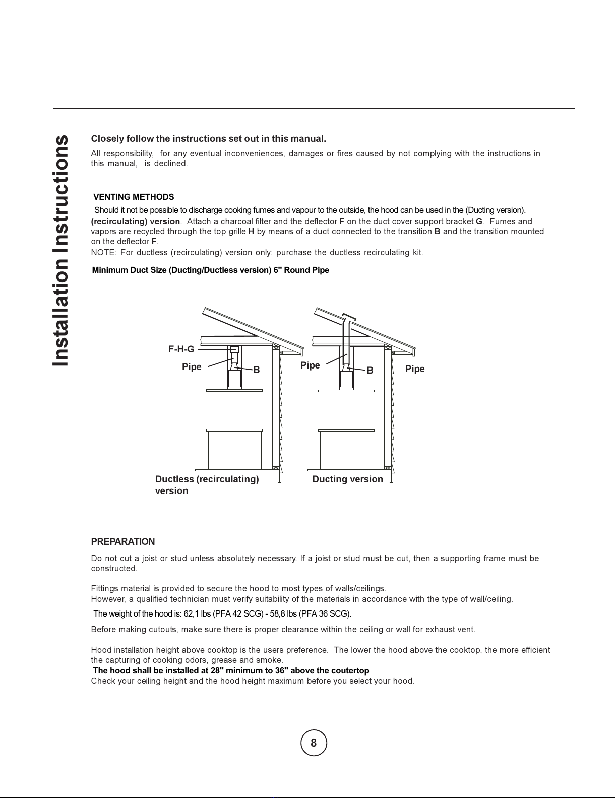
Clo ely follow the in truction et out in thi manual.
All responsibility, for any eventual inconveniences, damages or fires caused by not complying with the instructions in
this manual, is declined.
( eci culating) ve sion. Attach a charcoal filter and the deflector F on the duct cover support bracket G. Fumes and
vapors are recycled through the top grille H by means of a duct connected to the transition B and the transition mounted
on the deflector F.
NOT : For ductless (recirculating) version only: purchase the ductless recirculating kit.
PREPARATION
Do not cut a joist or stud unless absolutely necessary. If a joist or stud must be cut, then a supporting frame must be
constructed.
Fittings material is provided to secure the hood to most types of walls/ceilings.
However, a qualified technician must verify suitability of the materials in accordance with the type of wall/ceiling.
Before making cutouts, make sure there is proper clearance within the ceiling or wall for exhaust vent.
Hood installation height above cooktop is the users preference. The lower the hood above the cooktop, the more efficient
the capturing of cooking odors, grease and smoke.
Check your ceiling height and the hood height maximum before you select your hood.
F-H-G
B
B
Ducting ver ionDuctle (recirculating)
ver ion
Pipe
Pipe
Pipe
The hood shall be installed at 28" minimum to 36" above the coutertop
VENTING METHODS
Should it not be possible to discharge cooking fumes and vapour to the outside, the hood can be used in the (Ducting version).
The weight of the hood is: 62,1 lbs (PFA 42 SCG) - 58,8 lbs (PFA 36 SCG).
Minimum Duct Size (Ducting/Ductless version) 6" Round Pipe
8
All manuals and user guides at all-guides.com
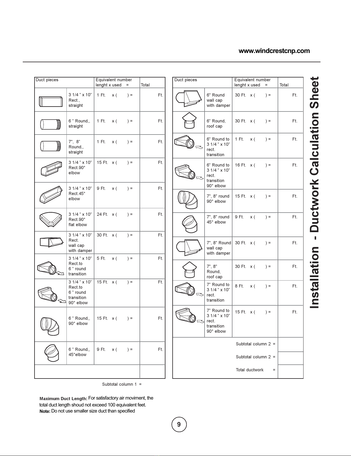
Installation - Ductwor Calculation Sheet
3 1/4 x 10
Rect.,
straight
6 Round,,
straight
7", 8
Round,,
straight
3 1/4 x 10
Rect.90°
elbow
3 1/4 x 10
Rect.45°
elbow
3 1/4 x 10
Rect.90°
flat elbow
3 1/4 x 10
Rect.
wall cap
with damper
3 1/4 x 10
Rect.to
6 round
transition
3 1/4 x 10
Rect.to
6 round
transition
90° elbow
6 Round,,
90° elbow
6 Round,,
45°elbow
1 Ft. x ( ) =
1 Ft. x ( ) =
1 Ft. x ( ) =
15 Ft. x ( ) =
9 Ft. x ( ) =
24 Ft. x ( ) =
30 Ft. x ( ) =
5 Ft. x ( ) =
15 Ft. x ( ) =
15 Ft. x ( ) =
9 Ft. x ( ) =
Ft.
Ft.
Ft.
Ft.
Ft.
Ft.
Ft.
Ft.
Ft.
Ft.
Ft.
6" Round
wall cap
with damper
6 Round,
roof cap
6 Round to
3 1/4 x 10
rect.
transition
6 Round to
3 1/4 x 10
rect.
transition
90° elbow
7", 8" round
90° elbow
7", 8" round
45° elbow
7", 8" Round
wall cap
with damper
7", 8"
Round,
roof cap
7 Round to
3 1/4 x 10
rect.
transition
7 Round to
3 1/4 x 10
rect.
transition
90° elbow
30 Ft. x ( ) =
30 Ft. x ( ) =
1 Ft. x ( ) =
16 Ft. x ( ) =
15 Ft. x ( ) =
9 Ft. x ( ) =
30 Ft. x ( ) =
30 Ft. x ( ) =
8 Ft. x ( ) =
15 Ft. x ( ) =
Ft.
Ft.
Ft.
Ft.
Ft.
Ft.
Ft.
Ft.
Ft.
Ft.
Duct pieces Equivalent number
lenght x used = Total
Duct pieces Equivalent number
lenght x used = Total
Subtotal column 2 =
Subtotal column 2 =
Total ductwork =
Subtotal column 1 =
Maximum Duct Length:
Note: Do not use smaller size duct than specified
total duct length shoud not exceed 100 equivalent feet.
For satisfactory air moviment, the
www.windcrestcnp.com
9
All manuals and user guides at all-guides.com
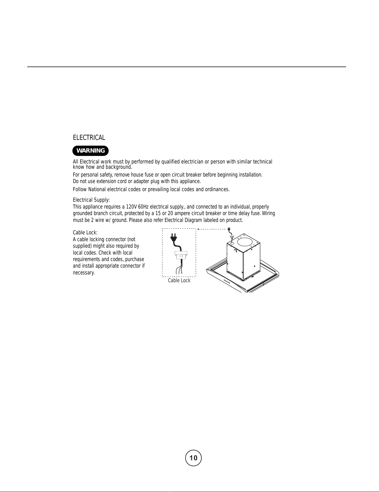
ELECTRICAL
All Electrical work must by performed by qualified electrician or person with similar technical
know how and background.
For personal safety, remove house fuse or open circuit breaker before beginning installation.
Do not use extension cord or adapter plug with this appliance.
Follow National electrical codes or prevailing local codes and ordinances.
Electrical Supply:
This appliance requires a 120V 60Hz electrical supply., and connected to an individual, properly
grounded branch circuit, protected by a 15 or 20 ampere circuit breaker or time delay fuse.Wiring
must be 2 wire w/ ground. Please also refer Electrical Diagram labeled on product.
Cable Lock:
A cable locking connector (not
supplied) might also required by
local codes. Check with local
requirements and codes, purchase
and install appropriate connector if
necessary. Cable Lock
WARNING
10
All manuals and user guides at all-guides.com
Installation
REAR
FRONT
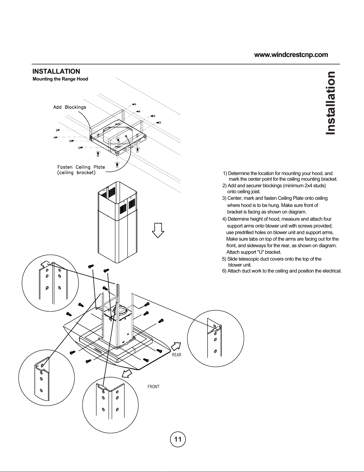
onto ceiling joist.
2) Add and securer blockings (minimum 2x4 studs)
3) Center, mark and fasten Ceiling Plate onto ceiling
bracket is facing as shown on diagram.
where hood is to be hung. Make sure front of
use predrilled holes on blower unit and support arms.
4) Determine height of hood, measure and attach four
support arms onto blower unit with screws provided;
Attach support "U" bracket.
Make sure tabs on top of the arms are facing out for the
front, and sideways for the rear, as shown on diagram.
11
www.windcrestcnp.com
INSTALLATION
Mounting the Range Hood
blower unit.
mark the center point for the ceiling mounting bracket.
1) Determine the location for mounting your hood, and
5) Slide telescopic duct covers onto the top of the
6) Attach duct work to the ceiling and position the electrical.
11
All manuals and user guides at all-guides.com
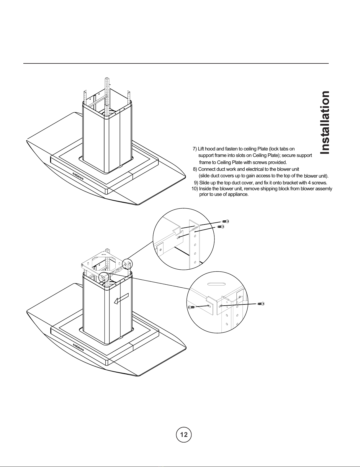
Installation
support frame into slots on Ceiling Plate); secure support
7) Lift hood and fasten to ceiling Plate (lock tabs on
frame to Ceiling Plate with screws provided.
12
10) Inside the blower unit, remove shipping block from blower assemly
blower unit).
(slide duct covers up to gain access to the top of the
8) Connect duct work and electrical to the blower unit
prior to use of appliance.
9) Slide up the top duct cover, and fix it onto bracket with 4 screws.
12
All manuals and user guides at all-guides.com
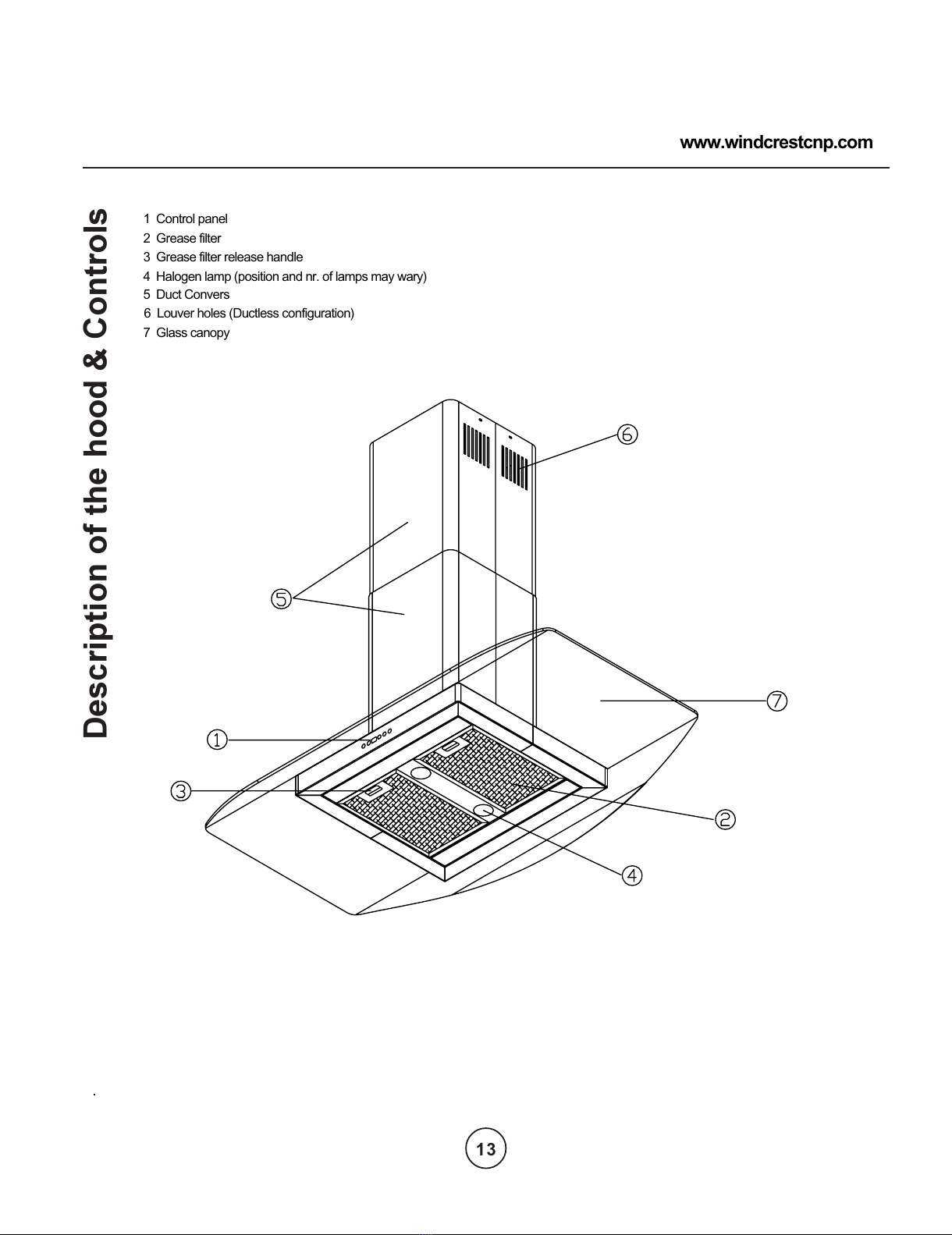
Description of the hood & Controls
..
2 Grease filter
3 Grease filter release handle
4 Halogen lamp (position and nr. of lamps may wary)
5 Duct Convers
6 Louver holes (Ductless configuration)
7 Glass canopy
1 Control panel
www.windcrestcnp.com
13
All manuals and user guides at all-guides.com
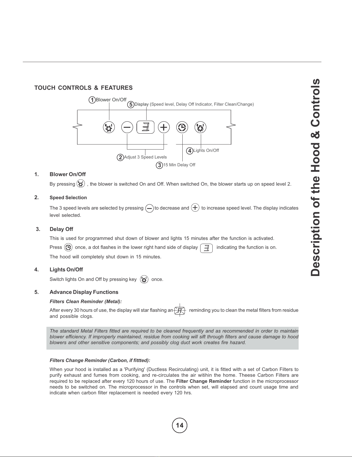
TOUCH CONTROLS & FEATURES
1. Blower On/Off
By pressing , the blower is switched On and Off. When switched On, the blower starts up on speed level 2.
2. Speed Selection
The 3 speed levels are selected by pressing to decrease and to increase speed level. The display indicates
level selected.
3. Delay Off
This is used for programmed shut down of blower and lights 15 minutes after the function is activated.
Press once, a dot flashes in the lower right hand side of display indicating the function is on.
The hood will completely shut down in 15 minutes.
4. Lights On/Off
Switch lights On and Off by pressing key once.
5. Advance Display Functions
Filters Clean Reminder (Metal):
After every 30 hours of use, the display will star flashing an reminding you to clean the metal filters from residue
and possible clogs.
The standard Metal Filters fitted are required to be cleaned frequently and as recommended in order to maintain
blower efficiency. If improperly maintained, residue from cooking will sift through filters and cause damage to hood
blowers and other sensitive components; and possibly clog duct work creates fire hazard.
Filters Change Reminder (Carbon, if fittted):
When your hood is installed as a 'Purifying' (Ductless Recirculating) unit, it is fitted with a set of Carbon Filters to
purify exhaust and fumes from cooking, and re-circulates the air witihin the home. Theese Carbon Filters are
required to be replaced after every 120 hours of use. The Filter Change Reminder function in the microprocessor
needs to be switched on. The microprocessor in the controls when set, will elapsed and count usage time and
indicate when carbon filter replacement is needed every 120 hrs.
Description of the Hood & Controls
15
2
3
4
Blower On/Off
Display (Speed level, Delay Off Indicator, Filter Clean/Change)
Adjust 3 Speed Levels
15 Min Delay Off
Lig ts On/Off
14
All manuals and user guides at all-guides.com
CONTROLS: FILTER CHANGE INDICATOR (Carbon Filters)
FIlter Change Reminder (Carbon, if fitted):
When your hood is installed as a 'Purifying' (Ductless Recirculating) unit, it is fitted with a set of Carbon FIlters to purify
exhaust and fumes from cooking, and re-circulates the air witihin the home. Theese Carbon Filters are required to be
replaced after every 120 hours of use. The Filter Change Reminder function in the microprocessor needs to be switched
on. The microprocessor in the controls when set, will elapsed and count usage time and indicate by a flashing when
carbon filter replacement is needed every 120 hrs.
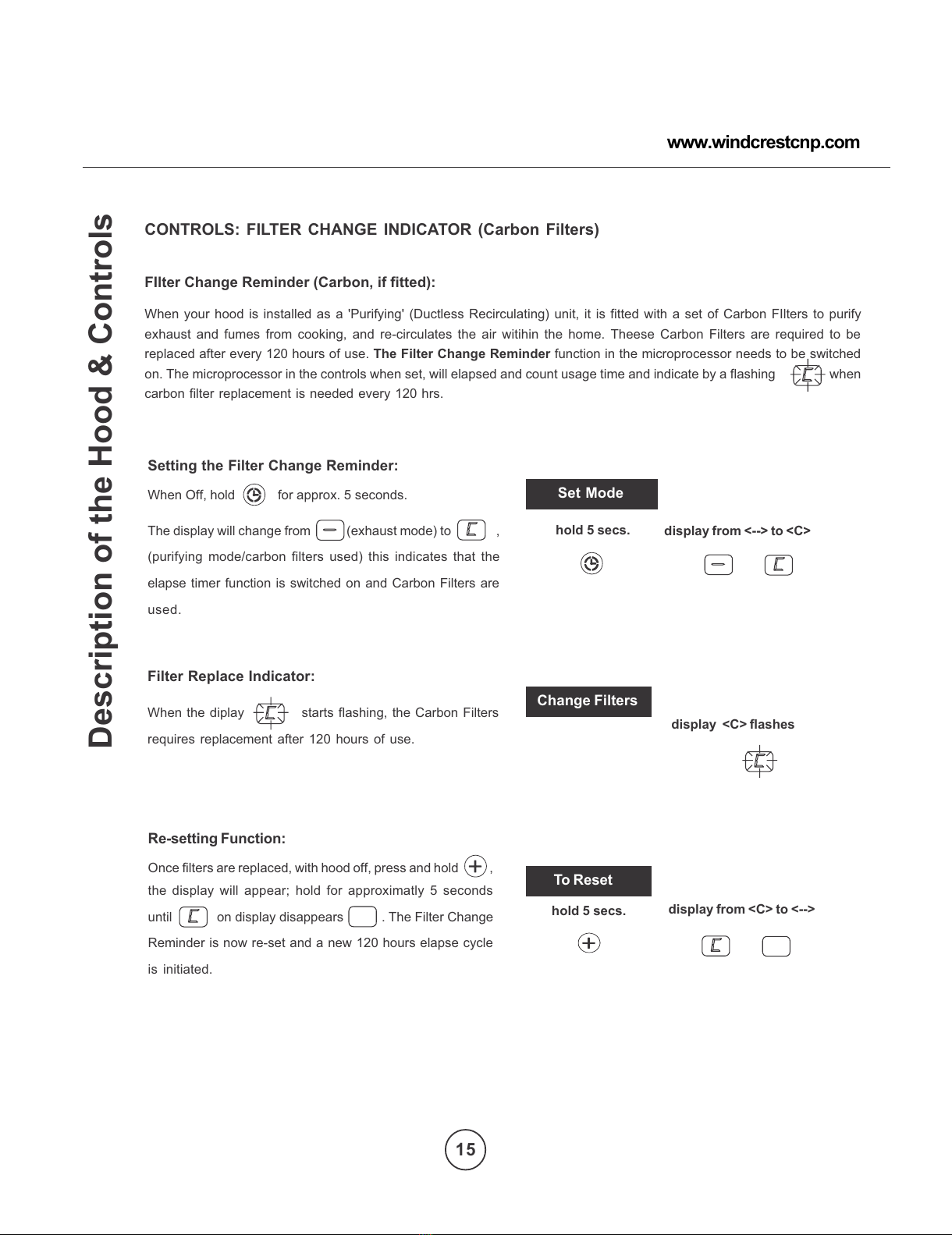
Setting the Filter Change Reminder:
When Off, hold for approx. 5 seconds.
The display will change from (exhaust mode) to ,
(purifying mode/carbon filters used) this indicates that the
elapse timer function is switched on and Carbon Filters are
used.
Filter Replace Indicator:
When the diplay starts flashing, the Carbon Filters
requires replacement after 120 hours of use.
Re-setting Function:
Once filters are replaced, with hood off, press and hold ,
the display will appear; hold for approximatly 5 seconds
until on display disappears . The Filter Change
Reminder is now re-set and a new 120 hours elapse cycle
is initiated.
Set Mode
Change Filters
To Reset
hold 5 secs. display from <--> to <C>
hold 5 secs. display from <C> to <-->
display <C> flashes
Description of the Hood & Controls
15
www.windcrestcnp.com
All manuals and user guides at all-guides.com
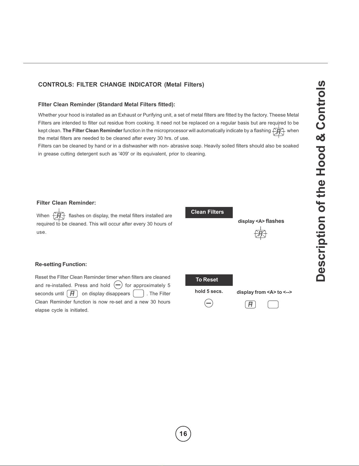
Filter Clean Reminder:
When flashes on display, the metal filters installed are
required to be cleaned. This will occur after every 30 hours of
use.
Re-setting Function:
Reset the FIlter Clean Reminder timer when filters are cleaned
and re-installed. Press and hold for approximately 5
seconds until on display disappears . The Filter
Clean Reminder function is now re-set and a new 30 hours
elapse cycle is initiated.
Set Mode
Clean Filters
To Reset
hold 5 secs. display from <A> to <-->
display <A>
flashes
CONTROLS: FILTER CHANGE INDICATOR (Metal Filters)
FIlter Clean Reminder (Standard Metal Filters fitted):
Whether your hood is installed as an Exhaust or Purifying unit, a set of metal fIlters are fitted by the factory. Theese Metal
Filters are intended to filter out residue from cooking. It need not be replaced on a regular basis but are required to be
kept clean. The Filter Clean Reminder function in the microprocessor will automatically indicate by a flashing when
the metal filters are needed to be cleaned after every 30 hrs. of use.
Filters can be cleaned by hand or in a dishwasher with non- abrasive soap. Heavily soiled filters should also be soaked
in grease cutting detergent such as '409' or its equivalent, prior to cleaning.
Description of the Hood & Controls
16
All manuals and user guides at all-guides.com
Maintenance
Prior to any maintenance operation ensure that the cooker hood is disconnected from the power supply.
The cooker hood should be cleaned regularly internally and externally.
For cleaning use a cloth moistened with a neutral liquid detergents. Avoid abrasive detergents.
Wa ning:
Failure to carry out the basic standards of the cleaning of the cooker hood and replacement of the filters may cause fire
risks.
Therefore we recommend oserving these instructions.
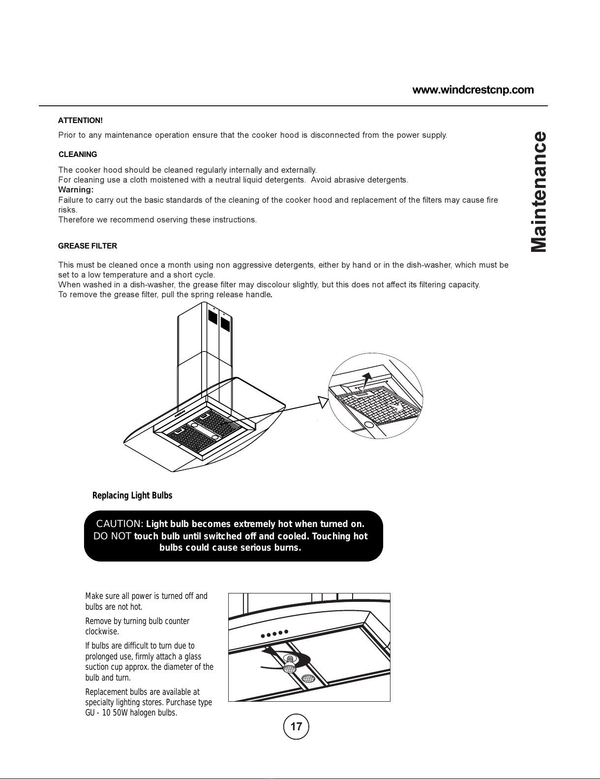
This must be cleaned once a month using non aggressive detergents, either by hand or in the dish-washer, which must be
set to a low temperature and a short cycle.
When washed in a dish-washer, the grease filter may discolour slightly, but this does not affect its filtering capacity.
To remove the grease filter, pull the spring release handle.
ATTENTION!
GREASE FILTER
CLEANING
17
www.windcrestcnp.com
Replacing Light Bulbs
Make sure all power is turned off and
bulbs are not hot.
Remove by turning bulb counter
clockwise.
If bulbs are difficult to turn due to
prolonged use, firmly attach a glass
suction cup approx. the diameter of the
bulb and turn.
Replacement bulbs are available at
specialty lighting stores. Purchase type
GU - 10 50W halogen bulbs.
CAUTION: Light bulb becomes extremely hot when turned on.
DO NOT touch bulb until switched off and cooled. Touching hot
bulbs could cause serious burns.
All manuals and user guides at all-guides.com
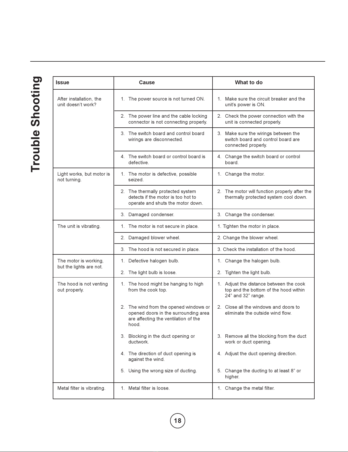
Trouble Shooting
After installation, the
unit doesnt work?
Light works, but motor is
not turning.
The unit is vibrating.
The motor is working,
but the lights are not.
The hood is not venting
out properly.
Metal filter is vibrating.
1. The power source is not turned ON.
2. The power line and the cable locking
connector is not connecting properly.
3. The switch board and control board
wirings are disconnected.
4. The switch board or control board is
defective.
1. The motor is defective, possible
seized.
2. The thermally protected system
detects if the motor is too hot to
operate and shuts the motor down.
3. Damaged condenser.
1. The motor is not secure in place.
2. Damaged blower wheel.
3. The hood is not secured in place.
1. Defective halogen bulb.
2. The light bulb is loose.
1. The hood might be hanging to high
from the cook top.
2. The wind from the opened windows or
opened doors in the surrounding area
are affecting the ventilation of the
hood.
3. Blocking in the duct opening or
ductwork.
4. The direction of duct opening is
against the wind.
5. Using the wrong size of ducting.
1. Metal filter is loose.
I ue Cau e What to do
1. Make sure the circuit breaker and the
units power is ON.
2. Check the power connection with the
unit is connected properly.
3. Make sure the wirings between the
switch board and control board are
connected properly.
4. Change the switch board or control
board.
1. Change the motor.
2. The motor will function properly after the
thermally protected system cool down.
3. Change the condenser.
1. Tighten the motor in place.
2. Change the blower wheel.
3. Check the installation of the hood.
1. Change the halogen bulb.
2. Tighten the light bulb.
1. Adjust the distance between the cook
top and the bottom of the hood within
24 and 32 range.
2. Close all the windows and doors to
eliminate the outside wind flow.
3. Remove all the blocking from the duct
work or duct opening.
4. Adjust the duct opening direction.
5. Change the ducting to at least 8 or
higher.
1. Change the metal filter.
18
All manuals and user guides at all-guides.com
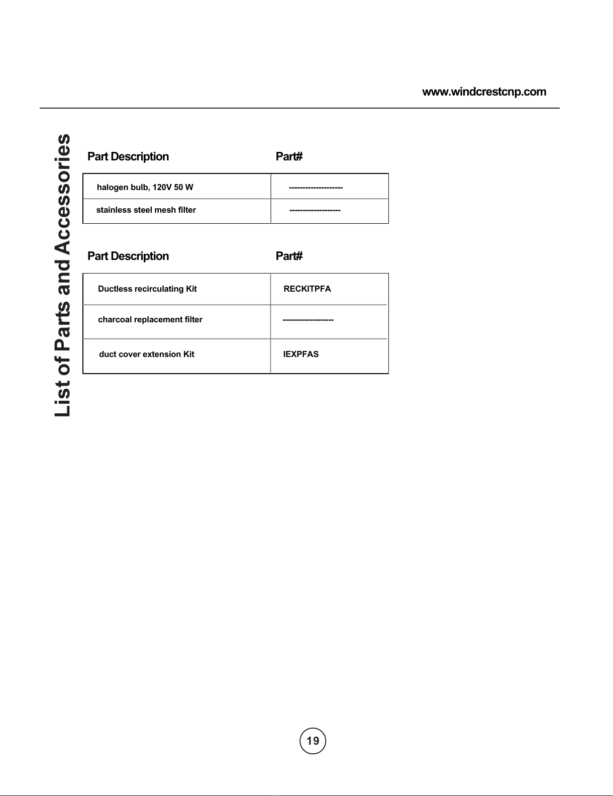
List of Parts and Accessories
stainless steel mesh filter -------------------
duct cover extension Kit IEXPFAS
Part Description Part#
Part Description Part#
halogen bulb, 120V 50 W --------------------
Ductless recirculating Kit RECKITPFA
charcoal replacement filter -------------------
www.windcrestcnp.com
19
All manuals and user guides at all-guides.com
This manual suits for next models
1
Table of contents
Languages:
Other CNP INDUSTRIES Ventilation Hood manuals


Popular Ventilation Hood manuals by other brands

ELICA
ELICA Horizonte Island Series Use, care and installation guide

Gorenje
Gorenje ONE DVG65W Instructions for use

AIRFORCE
AIRFORCE F162 90 D2 Glass Instruction on mounting and use

GE
GE PVB94DTBB installation instructions

Omega
Omega ORU90XL quick start guide

Howdens
Howdens Lamona LAM2400 User's installation guide


Whirlpool
Whirlpool 30 " Eye-Level Gas Range installation instructions

Xo
Xo XOI27S User instructions

Amica
Amica OWS 451 O instruction manual

Bosch
Bosch DHI665VGB Operating and installation instructions

Brillia
Brillia RAX9430SQB Installation instructions and operation manual

Novy
Novy 650 installation instructions