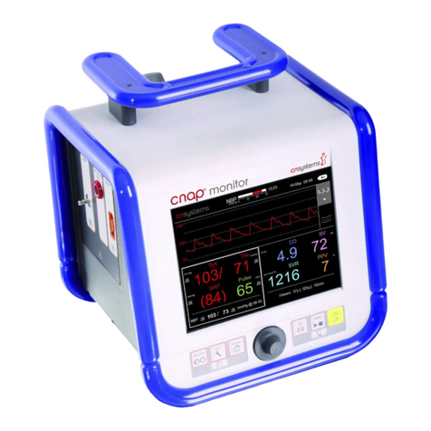
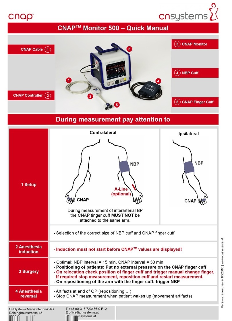
CNSystems CNAP Monitor 500 User manual


Edition: November 7
th
2012 Version: 3.5.1, PN: 21-FHZU-10002
he CNAP™ Monitor 500 meets the requirements of -mark
0408
according to the European standard for medical devices 93/42/EWG, annex IX
as amended by 2007/47/EC
The product starting with the serial number 0500-0917-xxxx was voluntarily tested according to
UL 60601-1:2003, CAN/CSA C22.2 No.601.1-M90
his manual refers to the following configuration:
Hardware: CNAP™ Monitor 500i and CNAP™ Monitor 500at (note that only the
CNAP™ Monitor 500at comes with a functional analog output port)
Software: Version 3.5R01
CNSystems Medizintechnik AG
Reininghausstrasse 13
8020 Graz
Austria
: +43 (0) 316 7 23456-0
F: +43 (0) 316 7 23456-2
E-mail: [email protected]
I: www.cnsystems.at

able of contents
CNAP™ Monitor 500 Page i Version 3.5.1, PN: 21-FHZU-10002
Table of contents
1
About this manual..........................................................................................................1-1
1.1
S OP, CAU ION, NO ES..........................................................................................1-1
1.2
Cross references.....................................................................................................1-1
1.3
Settings ................................................................................................................1-1
2
General information .......................................................................................................2-1
2.1
Warnings...............................................................................................................2-1
2.2
Precautions............................................................................................................2-1
2.2.1
General precautions .....................................................................................2-1
2.2.2
Blood pressure ............................................................................................2-2
2.3
Disposal ................................................................................................................2-3
2.4
Declaration of intended use .....................................................................................2-3
3
Introduction ..................................................................................................................3-1
3.1
General information ................................................................................................3-1
3.2
System components ...............................................................................................3-1
3.2.1
CNAP™ Monitor 500.....................................................................................3-2
3.2.2
CNAP™ hardware.........................................................................................3-5
3.2.3
NBP cuff .....................................................................................................3-6
3.3
Power supply .........................................................................................................3-7
3.3.1
Mains operation...........................................................................................3-7
3.3.2
Battery operation ........................................................................................3-7
3.4
First steps ........................................................................................................... 3-10
3.4.1
Power On/Off ............................................................................................ 3-10
3.4.2
Access/return to main screen ...................................................................... 3-11
3.4.3
Fast access keys........................................................................................ 3-12
3.4.4
Menu navigation – click-wheel control .......................................................... 3-13
3.4.5
Menu selection .......................................................................................... 3-13
3.5
Patient setup ....................................................................................................... 3-14
3.6
imer.................................................................................................................. 3-15
3.7
Perfusion Index .................................................................................................... 3-16
4
Monitor configuration .....................................................................................................4-1
4.1
Monitor settings .....................................................................................................4-1
4.2
Measurement settings .............................................................................................4-1
4.3
Service settings......................................................................................................4-2
4.4
BP Wave Out (patient monitors) ...............................................................................4-2
4.4.1
BP Wave Out configuration ...........................................................................4-2
4.4.2
Compatibility list..........................................................................................4-3
4.4.3
Zeroing ......................................................................................................4-4
4.5
Interfaces (optional) ...............................................................................................4-6
4.5.1
AUX Analog Out (analog output port) .............................................................4-6
4.5.2
Ethernet .....................................................................................................4-6
4.5.3
USB ...........................................................................................................4-6
5
Management of patient data............................................................................................5-1
5.1
Patient entry..........................................................................................................5-1
5.2
Editing of patient data.............................................................................................5-3

able of contents
CNAP™ Monitor 500 Page ii Version 3.5.1, PN: 21-FHZU-10002
5.3
Discharge ..............................................................................................................5-3
6
Alarm system ................................................................................................................6-1
6.1
Visual alarm signals ................................................................................................6-2
6.2
Acoustic alarm signals.............................................................................................6-3
6.3
Alarm system control ..............................................................................................6-4
6.3.1
Acknowledgement of alarms – Audio Off, Audio Pause......................................6-4
6.3.2
Pausing/switching off alarms – Alarms Paused, Alarms Off................................6-4
6.3.3
Reactivation of paused alarms - Alarms Off.....................................................6-5
6.4
Alarm limits ...........................................................................................................6-5
6.4.1
Display of individual alarm limits ...................................................................6-5
6.4.2
Alarm setup ................................................................................................6-5
6.4.3
Auto limits ..................................................................................................6-7
6.4.4
Alarm limits – factory settings.......................................................................6-7
6.5
Alarm history .........................................................................................................6-8
6.6
Alarm system function tests.....................................................................................6-9
6.7
Physiological alarms................................................................................................6-9
7
rends..........................................................................................................................7-1
7.1
rend – the menu for display options ........................................................................7-2
7.2
Setup....................................................................................................................7-3
7.2.1
rend views ................................................................................................7-3
7.2.2
Graphic trend..............................................................................................7-3
7.2.3
Numeric trends ...........................................................................................7-6
7.2.4
Alarm history ..............................................................................................7-7
7.2.5
Scrolling of trend views ................................................................................7-8
8
Printing ........................................................................................................................8-1
8.1
Launching print reports ...........................................................................................8-1
8.2
Canceling print reports............................................................................................8-2
8.3
Print reports ..........................................................................................................8-2
8.4
Print options ..........................................................................................................8-3
9
CNAP™ .........................................................................................................................9-1
9.1
General information ................................................................................................9-1
9.2
Safety precautions..................................................................................................9-2
9.3
Setup....................................................................................................................9-3
9.4
View features.........................................................................................................9-4
9.4.1
Blood pressure waveform .............................................................................9-4
9.4.2
rend view..................................................................................................9-4
9.4.3
Numeric values ...........................................................................................9-5
9.5
CNAP™ options ......................................................................................................9-6
10
NBP............................................................................................................................ 10-1
10.1
General information .............................................................................................. 10-1
10.2
Venous stasis....................................................................................................... 10-2
10.3
Safety precautions................................................................................................ 10-3
10.4
Setup.................................................................................................................. 10-4
10.5
View features....................................................................................................... 10-6
10.6
NBP options ......................................................................................................... 10-7
11
Cleaning and disinfection .............................................................................................. 11-1

able of contents
CNAP™ Monitor 500 Page iii Version 3.5.1, PN: 21-FHZU-10002
11.1
General precautions.............................................................................................. 11-1
11.2
Cleaning.............................................................................................................. 11-1
11.3
Disinfection.......................................................................................................... 11-2
12
echnical alarms and status messages ........................................................................... 12-1
12.1
Main unit ............................................................................................................. 12-2
12.1.1
Status messages ....................................................................................... 12-2
12.1.2
echnical alarms........................................................................................ 12-2
12.2
BP Wave Out (IBP) ............................................................................................... 12-3
12.2.1
Status messages ....................................................................................... 12-3
12.2.2
echnical alarms........................................................................................ 12-3
12.3
Printer ................................................................................................................ 12-4
12.3.1
echnical alarms........................................................................................ 12-4
12.4
CNAP™................................................................................................................ 12-4
12.4.1
Status messages ....................................................................................... 12-4
12.4.2
echnical alarms........................................................................................ 12-5
12.5
NBP .................................................................................................................... 12-8
12.5.1
Status messages ....................................................................................... 12-8
12.5.2
echnical alarms........................................................................................ 12-9
13
Appendix A – Glossary.................................................................................................. 13-1
13.1
Illustrations ......................................................................................................... 13-2
14
Appendix B – Accessories.............................................................................................. 14-1
14.1
CNAP™................................................................................................................ 14-1
14.2
NBP .................................................................................................................... 14-1
14.3
Printer ................................................................................................................ 14-2
14.3.1
Paper recommendation............................................................................... 14-2
14.4
Connections......................................................................................................... 14-2
14.5
Other accessories ................................................................................................. 14-2
15
Appendix C – echnical specifications ............................................................................. 15-1
15.1
CNAP™ Monitor 500.............................................................................................. 15-1
15.1.1
External mains adapter .............................................................................. 15-2
15.1.2
CNAP™ - continuous non-invasive arterial pressure ....................................... 15-3
15.1.3
NBP - non-invasive blood pressure............................................................... 15-3
15.1.4
Printer...................................................................................................... 15-4
15.2
Connections......................................................................................................... 15-4
15.3
Electromagnetic compatibility................................................................................. 15-6
15.4
Maintenance schedule ........................................................................................... 15-9
15.4.1
Safety inspection ....................................................................................... 15-9
15.4.2
Maintenance ........................................................................................... 15-10
15.5
Standards.......................................................................................................... 15-10
15.6
Declaration of conformity .................................................................................... 15-11

About this manual
CNAP™ Monitor 500 Page 1-1 Version 3.5.1, PN: 21-FHZU-10002
1About this manual
S OP, CAU ION, NO ES.........................................................................................................1-1
Cross references ...................................................................................................................1-1
Settings ...............................................................................................................................1-1
1.1 STOP, CAUTION, NOTES
In this manual the icons "S OP", "CAU ION", and "NO E" are used to indicate matters of particular
interest to keep in mind when operating the CNAP™ Monitor 500 or dealing with patients.
S OP
he S OP icon indicates important security-relevant information:
STOP:
•Check the correct positioning of the CNAP™ double finger cuff. Make sure that the cuff
is not positioned on the finger joints.
CAU ION
he CAU ION icon indicates important information referring to the correct utilization of the CNAP™
Monitor 500:
CAUTION:
•he lifetime cycle of a CNAP™ double finger cuff is 6 months if in constant use on pa-
tients, or 12 months at the most.
NO E
he NO E icon indicates helpful information referring to the utilization of the CNAP™ Monitor 500 and
its components:
NOTE:
•Use the graphics on the CNAP™ controller to determine the correct finger cuff size.
•If the size of a patient's finger is between two finger cuff sizes, use the larger CNAP™
finger cuff for the measurement.
1.2 Cross references
Cross references refer to chapters where the operator can find additional information about specific
topics. A cross reference includes the number and title of the chapter referred to (e.g. see chapter 2 –
General information).
1. Settings
Settings available for menu entries are listed as:
Menu item Description Setting
Brightness
Regulates the brightness of the F -display
20(20)100, Auto
Minimum (Increment) Maximum

General information
CNAP™ Monitor 500 Page 2-1 Version 3.5.1, PN: 21-FHZU-10002
2General information
Warnings..............................................................................................................................2-1
Precautions ..........................................................................................................................2-1
General precautions ..............................................................................................................2-1
Blood pressure......................................................................................................................2-2
Disposal ...............................................................................................................................2-3
Declaration of intended use ....................................................................................................2-3
2.1 Warnings
•he CNAP™ Monitor 500 is not designed for intracardial use.
•Do not connect the device's air connectors to an intravascular system!
•Do not use the oscillometric cuff on patients with vascular prostheses!
•Keep the CNAP™ Monitor 500 out of reach of children!
•he CNAP™ Monitor 500 is not fit for operation in potentially explosive surroundings, as may arise
from usage or storage of flammable anaesthetics, skin detergents or skin disinfectants. Also, do
not use the CNAP™ Monitor 500 in a possibly combustible atmosphere (i.e. if the ambient air con-
tains more than 25% of oxygen or nitrous oxide gas).
•he operator has to prevent prolonged impairment of the patient's blood circulation during the
measuring process by inspecting the concerned limbs regularly. his is particularly important in the
case of continuous blood pressure measurement. During normal use, the pressure in the finger cuff
will be the same as in the artery and therefore greater than normal venous pressure. As a result,
depending on variables like skin temperature, thickness, patient age, perfusion or presenting state,
venous congestion of the finger distal to the cuff may be observed which will quickly subside with
the discontinuation of monitoring (blue fingers). Check the monitoring area frequently and discon-
tinue the continuous blood pressure measurement and remove all air connectors immediately in
case of any signs of reduced blood circulation.
•Do not use the compressed air supply valves with any devices of a third party manufacturer.
•Each device is designed for the concurrent measurement of only one patient/test subject at a time.
Never measure two or more patients at the same time, applying only one device!
•Please pay attention to the precautions regarding electromagnetic compatibility (see chapter 15.3 –
Electromagnetic compatibility).
•In perioperative settings, the CNAP™ Monitor 500 is not to be used without additional ECG moni-
toring for independent patient monitoring.
2.2 Precautions
2.2.1 General precautions
•he CNAP™ Monitor 500 is a device of protection class II. he input ports of type BF are protected
from defibrillation.
•According to the regulations of IEC 601-2-30/EN 60601-2-30, non-invasive blood pressure meas-
urement is fit for use during electrosurgical surgery as well as during discharge of a cardiac defi-
brillator.
•he CNAP™ Monitor 500 meets the requirements of EN 60601-1-1 and can be used next to pa-
tients without restrictions.
•While using the CNAP™ Monitor 500, avoid compressing the air hoses or reducing their diameter in
any way (e.g. by bending the cables) as this could impair the quality of the measuring signals.
•No liquids must ingress the CNAP™ Monitor 500. In case this should happen, the instrument must
not be started up again until after inspection by a qualified technician.
•Any chemicals needed for the use and maintenance of the device are only to be prepared and
stored in correspondingly designated containers in order to prevent confusion entailing possible se-
rious consequences.
•Medical devices like the CNAP™ Monitor 500 are to be operated only by accordingly trained persons
who can guarantee the proper handling of the device on the basis of their special training or their
skills and practical experience.
•he operator has to be familiar with the operation of the CNAP™ Monitor 500. Before each meas-
urement process, the operator has to check and control the due condition, operational reliability
and functional safety of the device.

General information
CNAP™ Monitor 500 Page 2-2 Version 3.5.1, PN: 21-FHZU-10002
•Before connecting any cables to a patient, all connecting cables need to be visually inspected for
signs of damage. Any faulty parts (e.g. cables or plugs) are to be replaced immediately. Only origi-
nal CNSystems Medizintechnik AG accessories and replacement parts are to be used.
•Please pay close attention to the proper storage of the device: Do not bend the cables or hoses
excessively or coil them up too tightly, as this might result in damaging cables and hoses. Any
damaged cables or hoses are to be replaced immediately.
•ake care to ensure regular and sufficient air circulation around the device. Also take into consid-
eration the necessary environmental conditions specified in this manual (see Appendix C – echnical
specifications).
•A thorough examination of the device for its operational reliability is due on a regular basis (ap-
prox. once every month).
•his manual is an integral part of the CNAP™ Monitor 500. By adhering to its safety measures and
recommendations, the operator ensures the correct use and operation of the device as well as the
operators' and the patients' safety. Notes and precautions of particular importance are highlighted
by the following symbols: , , (see chapter 1 – About this manual).
•In order to ensure the device's faultless functioning, accuracy of measurement and immunity of
interference as well as the patients' safety, use only original CNSystems accessories and replace-
ment parts. CNSystems will not warrant for faultless functioning and operation if third party manu-
facturer replacement parts and accessories are used.
•CNSystems Medizintechnik AG is not liable for any warranty claim for possible damages if parts of
third party manufacturers are used.
•CNSystems warrants for faultless functioning, reliability and safety of this device on the condition
that the procedures of installation, extensions and enhancements, new settings, alterations, main-
tenance and repair are exclusively carried out by CNSystems or a company authorized by CNSys-
tems. In addition, the appliance and operation of the CNAP™ Monitor 500 must be in accordance
with the instructions in this operator's manual.
•All copyrights concerning the devices, procedures, electronic circuits, software programs and labels
mentioned in this manual are reserved to CNSystems Medizintechnik AG.
•Never touch the AUX, Ethernet and USB interfaces together with the patient.
•All devices that get connected to the AUX, Ethernet and USB interfaces must meet EN 606950-1
standard.
2.2.2 Blood pressure
CNAP™:
•In rare cases, it might happen that the device is unable to detect a continuous blood pressure sig-
nal. Usually, the middle and index fingers are best suited for applying the finger cuffs as their pha-
langes are the longest. If it is not possible to obtain a continuous blood pressure signal, it is, in
most cases, caused by a vasopathy. Warming the hand, for example in warm water, may solve the
problem.
•If no continuous blood pressure waveform is displayed within a few minutes, it is probably due to
an insufficient blood flow in the fingers. In this case, try using another pair of fingers or the other
hand. If this is not successful either, please check if the labeling on the CNAP™ double finger cuff
(symbol) is on the side of the back of the hand.
•o avoid mechanical damage to the finger cuffs, never start measuring without a finger in the
blood pressure cuff. Also, remove all objects (e.g. rings) from the fingers before measuring.
•During NBP measurements or venous stasis, the graphic display of the blood pressure waveform
may be physiologically influenced.
•Limitations: In certain cases, a continuous blood pressure measurement is not reliable and/or not
possible:
oWeak signal shown through indicator: low PI ≤ 1 on the CNAP™ Monitor 500 (see chapter 3.7 -
PI)
oReduced peripheral blood flow (peripheral shock, hypothermia, extreme centralization, extreme
hypothermia)
oArterial vascular diseases (arteriosclerosis, Raynaud’s syndrome, endarteritis obliterans, colla-
genosis, extremely advanced vascular diseases PAOD)
oNBP limitations (see below)

General information
CNAP™ Monitor 500 Page 2-3 Version 3.5.1, PN: 21-FHZU-10002
NBP:
•Under the following conditions there might be a decrease in accuracy of the oscillometric blood
pressure measurement:
oweak pulse
oarrhythmia
opatient movement artifacts
otremor artifacts
orespiratory artifacts
2. Disposal
Packaging material
•he packing material of the CNAP™ Monitor 500 is to be disposed of according to the respective
national regulations.
Device and accessories
•Dispose of the CNAP™ Monitor 500 and any accessories at the end of the products' lifecycles in
accordance with respective national regulations or send the parts back to CNSystems Medizintech-
nik AG.
2.4 Declaration of intended use
he CNAP™ Monitor 500 is intended for the non-invasive continuous measurement and display of
blood pressure (blood pressure waveform, beat-to-beat numerics, systolic, diastolic and mean pres-
sures), and pulse rate in hospitals, clinical institutions, medical practices and outpatient settings. Fur-
thermore, the display of alarms can be set for the parameters of blood pressure and pulse rate. he
CNAP™ Monitor 500 is to be used for adults and pediatric patients from the age of 4 years and is to be
operated by medical professional staff.

Introduction
CNAP™ Monitor 500 Page 3-1 Version 3.5.1, PN: 21-FHZU-10002
Introduction
General information...............................................................................................................3-1
System components ..............................................................................................................3-1
CNAP™ Monitor 500...............................................................................................................3-2
CNAP™ hardware ..................................................................................................................3-5
CNAP™ double finger cuff.......................................................................................................3-5
CNAP™ controller ..................................................................................................................3-6
CNAP™ cable ........................................................................................................................3-6
NBP cuff...............................................................................................................................3-6
Power supply ........................................................................................................................3-7
Mains operation ....................................................................................................................3-7
Battery operation ..................................................................................................................3-7
First steps .......................................................................................................................... 3-10
Power on/off....................................................................................................................... 3-10
Access/return to main screen................................................................................................ 3-11
Fast access keys ................................................................................................................. 3-12
Menu navigation – click-wheel control.................................................................................... 3-13
Menu selection.................................................................................................................... 3-13
Patient setup ...................................................................................................................... 3-14
imer................................................................................................................................. 3-15
Perfusion Index................................................................................................................... 3-16
.1 General information
he CNAP™ Monitor 500 is suitable for monitoring in
Adult
and
Pediatric
patients (from the age of
4 years). he CNAP™ Monitor 500 is in principle designed for being operated as a stand-alone device.
If required, however, it can be connected with other patient monitoring systems (
BP Wave Out
analog output port for CNAP™ blood pressure waveform) and other devices (USB, Ethernet).
NOTE:
•Upon production of the CNAP™ monitor two models, “500i“ and “500at“, are differenti-
ated. While the CNAP™
monitor “500i“ resembles the basic device configuration for
use of blood pressure monitoring (i.e. operating theaters, intensive care units), the
CNAP™ monitor “500at“ in addition enables the “AUX (analog output port)“ for trans-
ferring the analog blood pressure waveform to other devices.
.2 System components
he basic configuration of the monitor consists of the following components:
1. CNAP™ Monitor 500
2. CNAP™ hardware (CNAP™ double finger cuff, CNAP™ controller, CNAP™ cable)
3. NBP cuff

Introduction
CNAP™ Monitor 500 Page 3-2 Version 3.5.1, PN: 21-FHZU-10002
.2.1 CNAP™ Monitor 500
Illustration 1: Front view
Carrying handle
Display
Battery LED
Click-wheel control
Power LED
Control panel
Illustration 2: Patient connectors
CNAP™ cable port
BP Wave Out: analog output
port
NBP cuff connector
1
5
6
1
2
4
2

Introduction
CNAP™ Monitor 500 Page 3-3 Version 3.5.1, PN: 21-FHZU-10002
Illustration : Printer, interface, power supply
hermal printer
Mains power port
USB connector: software
updates
Ethernet connector
AUX: analog output port
(only functioning with the
CNAP™ Monitor 500at)
Illustration 4: Back view
Holding device channel (op-
tional)
ype plate
1
2
4
1
2
5

Introduction
CNAP™ Monitor 500 Page 3-4 Version 3.5.1, PN: 21-FHZU-10002
CNAP™ Monitor 500 symbols
he following table describes all symbols in use on the CNAP™ Monitor 500 and its components:
No. Symbol Description
1
•
Power On/Off
(monitor on/off)
2
•
Setup
(monitor, measurement, service settings)
3
•
Main Screen
(return to main screen)
4
•
Print
5
•
Start/Stop
(of a measurement)
6
•
Alarm Pause/Off
7
•Input port of type BF is protected from defibrillation pulses
8
•Ethernet connector
9
•USB connector
10 +18V
•18 V DC supply required
11 AUX •Analog output port
12
2007 01
•Production date
13
Device meets the European standard for medical devices 93/42/EWG,
Appandix IX in the changed version 2007/47/EG, annex IX as am-
ended by 2007/47/EC
14
•Recycle damaged sealed lead gel battery
15
•Caution: see accompanying documents
16
•Separate disposal of electric and electronic appliances
17
•Protection class II

Introduction
CNAP™ Monitor 500 Page 3-5 Version 3.5.1, PN: 21-FHZU-10002
.2.2 CNAP™ hardware
Illustration 5: CNAP™ Monitor 500
CNAP™ Monitor 500
CNAP™ hardware
NBP hardware
.2.2.1 CNAP™ double finger cuff
he CNAP™ double finger cuff comes in three sizes, each size being marked by a different colored
hood.
Illustration 6: CNAP™ finger cuffs
Size Diameter (mm) Color
L 24 - 28 Dark red
M 18 - 24 Dark blue
S 10 - 18 Light blue
1
2

Introduction
CNAP™ Monitor 500 Page 3-6 Version 3.5.1, PN: 21-FHZU-10002
.2.2.2 CNAP™ controller
Illustration 7: CNAP™ controller
.2.2. CNAP™ cable
Illustration 8: CNAP™ cable
.2. NBP cuff
he NBP cuff is intended for oscillometric blood pressure measurement and is available in four sizes:
Illustration 9: NBP cuff
Size Arm circumference
(cm)
Child 12 - 19
Small Adult 17 - 25
Adult 23 - 33
Large Adult 31 - 40
he CNAP™ controller connects the CNAP™ double
finger cuff and the monitor via the CNAP™ cable.
he jacks for the CNAP™ double finger cuff and the
CNAP™ cable are adequately designed so as to avoid
any confusion when putting the cables into the cor-
responding jacks.
•
he graphics on the upside of the CNAP™
controller help choosing the right size of CNAP™
double finger cuff.
•
he CNAP™ controller is fastened to the
patient's forearm by means of the CNAP™ fore-
arm fixing cuff with a Velcro fastener.
•
he fixture for CNAP™ controller connects
the CNAP™ forearm fixing cuff mechanically to
the CNAP™ controller. he fixture for CNAP™
controller needs to be setup-up centrally (see
also illustration 18).
he CNAP™ cable connects the monitor and the
CNAP™ controller.
1
2

Introduction
CNAP™ Monitor 500 Page 3-7 Version 3.5.1, PN: 21-FHZU-10002
. Power supply
he CNAP™ Monitor 500 is supplied with power by means of either mains operation via an external
power adapter or by an integrated sealed lead gel battery. In case of power supply interruptions or
even power outage, the monitor will automatically switch to battery operation.
CAUTION:
•Carefully read and keep in mind the precautions regarding power supply.
. .1 Mains operation
During mains operation, the CNAP™ Monitor 500 is connected to a power adapter suited for a supply
voltage of 100-240 VAC (± 10%) and a mains frequency of 50/60 Hz (see Appendix C – echnical
specifications). When the CNAP™ Monitor 500 is connected to the mains power supply, the integrated
sealed lead gel battery is recharged as well. here is no time limit on the monitor being on mains op-
eration.
he CNAP™ Monitor 500 can be connected to a supply network system according to CISPR 11.
NOTE:
•he battery recharge symbol on the battery status of the F -display shows
when the integrated battery is being recharged.
•he battery status indicates the present battery charge status when the monitor is
running on battery (without mains power supply).
CAUTION:
•Do not use any power supply accessories, but those intended and authorized by
CNSystems Medizintechnik AG for utilization with the monitor!
Illustration 10: Power cord
Power cord
Power adapter
Cable connecting power adapter
and monitor
. .2 Battery operation
he integrated sealed lead gel battery enables the CNAP™ Monitor 500 to operate on battery for up to
120 minutes, depending on the CNAP™ calibration intervals, printer use and brightness of display.
When the CNAP™ Monitor 500 is connected to the mains power supply, the integrated sealed lead gel
battery is recharged as well. If the monitor runs on battery, the battery charge status will be indicated
on the F -display in 25% steps. he battery charge status is also indicated via the battery LED on
the front side of the monitor.
2
1

Introduction
CNAP™ Monitor 500 Page 3-8 Version 3.5.1, PN: 21-FHZU-10002
LED color Battery charge status
Green Device runs on battery, battery charge status 100 – 25%
Orange Device runs on battery, battery charge status ≤ 25%
Red Device runs on battery, automatic shutdown within 15 minutes
In addition, a low battery charge status (5 minutes of remaining operation time on battery) is indi-
cated by the status message
MU: Battery Low
, a depleted battery by
MU: Battery Depleted
on the F -display (see battery status below). For security reasons, the measurement is stopped with
a depleted battery and the monitor is shut down automatically.
STOP:
•Damaged or time-worn batteries might considerably reduce the maximal operating
time on battery. he accuracy of the device's battery charge status is only guaran-
teed when using undamaged batteries and under normal operation conditions.
CAUTION:
•otal discharge may damage the battery. herefore charge the battery at every op-
portunity.
•Immediately charge the battery with a battery charge status ≤ 25%, or as soon as
possible and for at least 5 hours at ≤ 50%.
•Extreme temperatures might impair your battery performance. For optimal operabil-
ity, charge and use the battery at temperatures < 35°C (95°F).
•In the case of infrequent use, charge the battery at least every 3 weeks for at least 5
hours.
•In order to guarantee a long product lifetime, preferably use the CNAP™ Monitor 500
in mains operation.
•When disposing of used batteries, adhere to your local waste disposal regulations.
•Do not use any batteries but those authorized by CNSystems. Use of non-authorized
batteries might damage the monitor.
•Before turning on the appliance for the first time, be sure to charge the integrated
sealed lead gel battery for 4.5 hours.
•In order to guarantee safe operability of the CNAP™ Monitor 500, the battery has to
be replaced after 24 months in the course of maintenance service.
NOTE:
•When switching from mains operation to battery operation, it can take up to a minute
until the battery charge status is displayed.
•he thermal printer cannot be operated when the battery charge status is ≤ 25%.
•During display of a status message or alarm, the battery symbol will be faded out –
however, a critical battery status can be seen through the LED color being orange or
red.

Introduction
CNAP™ Monitor 500 Page 3-9 Version 3.5.1, PN: 21-FHZU-10002
Battery status
Symbol Battery charge status Resulting measure
•Battery charge status 100%
•Battery charge status 50% •Switch to mains operation via power
adapter as soon as possible
•Very low battery charge status (<
25%), battery operation still possible
•Immediately switch to mains operation
via power adapter
•Printing deactivated
•Current print job cancelled
•echnical alarm
MU: Battery Low
•Battery depleted, operation possible
for 5 minutes at most; monitor is
switched off
•Immediately switch to mains operation
via power adapter
•echnical alarm
MU: Battery De-
pleted
•Current measurement discontinued,
monitor switched off automatically
•Battery malfunction, acoustic techni-
cal alarm signal •Call a service technician (CNSystems)
•Battery is being charged while run-
ning on mains power
•Fully charged while running on
mains power

Introduction
CNAP™ Monitor 500 Page 3-10 Version 3.5.1, PN: 21-FHZU-10002
.4 First steps
.4.1 Power On/Off
he
Power On/Off
key is located in the left lower corner on the front side of the device.
Illustration 11: Front view
Switching on the monitor
he CNAP™ Monitor 500 is switched on by pressing the
Power On/Off
key located on the front side
of the device for two seconds. While the CNAP™ Monitor 500 is booting up, device and software infor-
mation is displayed on the splash screen. he green power LED indicates the operation status of the
device. he operating system of the monitor initializes and performs a system self-test, then the main
screen is displayed.
In addition, the monitor also performs an automatic function test of its alarm system during starting-
up time (see chapter 6 – Alarm system).
Illustration 12: Splash screen

Introduction
CNAP™ Monitor 500 Page 3-11 Version 3.5.1, PN: 21-FHZU-10002
Switching off the monitor
he CNAP™ Monitor 500 is switched off by pressing the
Power On/Off
key located on the front side
of the device for 2 seconds.
CAUTION:
•he
Power On/Off
key does not interrupt the monitor's power supply. In order to
interrupt power supply, the operator needs to disconnect the power cord.
.4.2 Access/return to main screen
After having started the monitor, the main screen appears which displays all measuring parameters
and signals and enables the operator to access all menus.
Arrangement of the screen:
Alarm frame
CNAP™ Signal view
Trend frame
Parameter frame
Navigation frame
Battery charge and
printer status
Illustration 1 : Main screen
NOTE:
•In order to return to the main screen from any submenu, just press the
Main
Screen
key on the front of the monitor.
1
2
4
5
6
Other manuals for CNAP Monitor 500
1
Table of contents
Other CNSystems Medical Equipment manuals
Popular Medical Equipment manuals by other brands

Harvest Healthcare
Harvest Healthcare BUMPERS General User/ Safety Guide

medi
medi 2 in 1 Instructions for use

ChemoMetec
ChemoMetec NucleoCounter NC-3000 FlexiCyte quick guide

importvet
importvet SV-2 user manual

Coviden
Coviden Nellcor Series Operator's manual

Stryker Medical
Stryker Medical ST104 Maintenance manual