manuals.online logo
Brands
  1. Home
  2. •
  3. Brands
  4. •
  5. Cobalt Digital Inc
  6. •
  7. Power Supply
  8. •
  9. Cobalt Digital Inc DCP-SPS12 User manual

Cobalt Digital Inc DCP-SPS12 User manual

The part number for the complete power supply product is: DCP-SPS12.
The part number for the Interface circuit board only is: DCP-SPCB.
Each complete power supply 1-pack contains the following items:
2 x 12v, 1.5 amp regulated DC switch-mode power supplies (World approved / World voltage)
1 x DCP-SPCB power supply connecon circuit board.
Depending on your locaon, we will also include the following mains power plug adapters:
DCP-SPS12 AU - For Australia and Asia. NO mains plug adapters are required or included
DCP-SPS12 US - For North America. Two USA type mains adapters are included
DCP-SPS12 UK - For the United Kingdom. Two UK type mains adapters are included
DCP-SPS12 EU - For use in Europe. Two EU type mains adapters are included
Using and connecng the DCP-SPS12 or DCP-SPCB.
This product is intended for indoor hobby use only. It is not suitable for un-supervised use by
children of any age. As with all electronic products, especially mains-connected products, it is
important that you read & understand these instrucons before use.
Please be aware that wrong connecon or misuse will invalidate all warranes and may also
cause irreversible or serious damage to any connected items. Therefore we ask you to carefully
observe the instrucons and diagrams in this manual and wire DCP-SPS12 or DCP-SPCB in ac-
cordance to the informaon we have included into this manual.
Basic connecon guidelines for DCP-SPS12 and DCP-SPCB (Power Input side)
(1) Input Connecons for the DCP-SPCB board:
The SPS12 “Set” is supplied with the DCP-SPCB
and 2 x 12v 1.5 amp power supplies that should
be connected directly to the two power input
sockets. The power supplies that we include are
ed with the correct plugs making this easy.
(2) If you intend to use DCP-SPCB with your own
power supplies, limit the voltage to 6~15v DC.
Both power supplies should be idencal. Quality maers in power delivery so please be
quite sure that the power supplies that you choose are marked “regulated power sup-
plies” and that the plug is both the correct size and has a posive (+) centre connecon.
TIP: Look for plug packs with a set of adapters. Many brands are sold with a series of
common plug size adapters. These will always include the correct plugs for DCP-SPCB.
(3) Plug adapters are not usually xed polarity. So - please be sure to t adapters correctly
so that the centre-pin is posive or your DCP-SPCB will not work and may be damaged.
Basic connecon guidelines for DCP-SPS12 and DCP-SPCB (Power Output side)
This combinaon of two individual power supplies with
DCP-SPCB creates a 3-wire (-) (+/-) (+) power supply
that simplies polarity-change based switching via its
common terminal structure, making wiring easier.
Using it in place of a 2-wire power supply will greatly
reduce the number of wires you’ll need to run around
the layout and will mean only half as much soldering!
(1) Using the DCP-SPS12 with Alpha-Switch A
This is a very simple connecon to make. Just connect
the 3-wire output terminals of your DCP-SPCB power supply adapter to the 3 -wire power input
terminals of your Alpha-Switch PCB as per this illustraon. DCCconcepts provide a 3-wire ribbon
cable to make this neat and dy too.
The part number for the Ribbon Wire is DCD-RGB and each pack contains 5 metres.
Left Common Right
α
To the next
Switch-A
α
DCP-SPS12 Split-Rail Power Supply
obalt
C
DCP-SPS12 Split-Rail Power Supply
obalt
C Informaon, overview & input connecons Output connecon: Alpha-Switch & DCP-CPS
The DCP-SPS12 power supply includes 2 x high quality 1.5A wall-plug type power supplies.
If wired in this it way will easily handle 20 or more Alpha-Switch Analog Switch packs
The DCCconcepts DCP-SPS12 contains power supplies manufactured,
tested and approved for use world wide. It is guaranteed for 12 months
We have done our best to provide clear usage instrucons. We advise
you to follow these instrucons carefully and ask you to contact us if
you need further advice (email [email protected]) as incorrect
use may cause damage not covered by any warranty or guarantees.
Part # DCP-SPS12 (complete set)
Barcode Here Please
Basic connecon guidelines for DCP-SPS12 and DCP-SPCB (Power Output side)
Our new switch pack DCP-PNP has that name because it makes control panel really easy for
those who want LED indicators… Each LED is already pre-wired for plug and play assembly, and
this reduces the need for soldering when creang a control panel by an esmated 75%.
Using The DCP-SPCB with this new switch pack give you even more simplicaon as we have
designed them to work together, making control panel creaon easier than ever.
(2) Using the DCP-SPS12 adapter with the “Plug and Play” Analog Switch pack DCP-PNP
Available March 2016, this Analog control switch pack is perfect for control of all Analog Cobalt
motors or any low current device controlled by “reversing DC”.
With each DCP-PNP switch pack actually cosng less than you will pay for individual parts from
a local store, this switch pack includes BOTH individual and red/green LEDs so you can make
your panel any way you want!
Even beer, it takes the same easy-to-use “Plug and Play” approach of Cobalt Alpha-Switch for
the installaon of its Chrome-bezel mount control panel LEDS reducing the need for soldering to
simple connecon of power and motor control wires!
Wiring this switch pack using the DCP-SPCB is simple and easy to do, as this drawing shows.
 Connect the DCP-SPCB power supply adapter and the switch with our 3-wire ribbon cable,
then do the same between all of the switches.
 Connect each switch to a Cobalt iP Analog, Cobalt Omega or similar motor with a light 2-wire
cable then just plug in the LEDs and you are done!
DCP-SPS12 Split-Rail Power Supply
obalt
C Using DCP-SPS12 and DCP-PNP together
Basic connecon guidelines for DCP-SPS12 and DCP-SPCB (Power Output side)
As we menoned earlier - using it in place of a 2-wire power supply will greatly reduce wiring
complexity and more than halve the number of wires you’ll need to run around the layout.
Here is an example using standard SPDT (single pole double throw) switches.
(3) Using the DCP-SPS12 to power Cobalt or similar reversing-DC point/turnout motors
with standard SPDT Switches such as those supplied in our DCP-CMS-SP switch pack
and also available at many electronic parts supply stores.
The wiring connecons to do this are as follows:
* Common (Centre) output terminal of the DCP-SPCB should be connected directly to
one of the DC power input terminals of the Cobalt or other brand analog turnout motor.
This is the GREEN wire in the diagram below. If you have more than one, just link this
wire to all of them as we have done in this example.
* Le to one output terminal of an On-On type SPDT Switch. (RED wire in the diagram)
* Right output terminal of the DCP-SPCB should be connected to the other side of the
On-On type SPDT Switch. (The BLACK wire in the diagram)
* FINALLY Connect the common centre terminal of each SPDT switch to the other DC
power input terminal side of the Cobalt iP Analog, Cobalt Omega or similar other-brand
motor. This is shown by the BLUE wire in the diagram)
This diagram explains the process clearly.
DCP-SPS12 Split-Rail Power Supply
obalt
C Output connecon: SPDT wiring diagram
The DCP-SPS12 power supply
includes 2 x high quality 1.5A
wall-plug type power supplies.
If wired in this it way will easily
handle more than 200 Cobalt
Omega or iP Analog motors
The DCP-SPS12 power supply
includes 2 x high quality 1.5A
wall-plug type power supplies.
If wired in this it way will easily
handle more than 200 Cobalt
Omega or iP Analog motors

This manual suits for next models

1

Other Cobalt Digital Inc Power Supply manuals

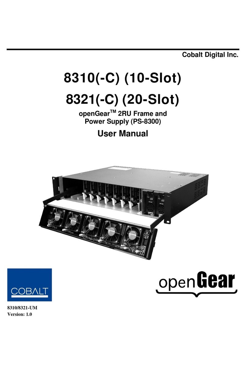
Cobalt Digital Inc 8310(-C) User manual

Cobalt Digital Inc

Cobalt Digital Inc 8310(-C) User manual

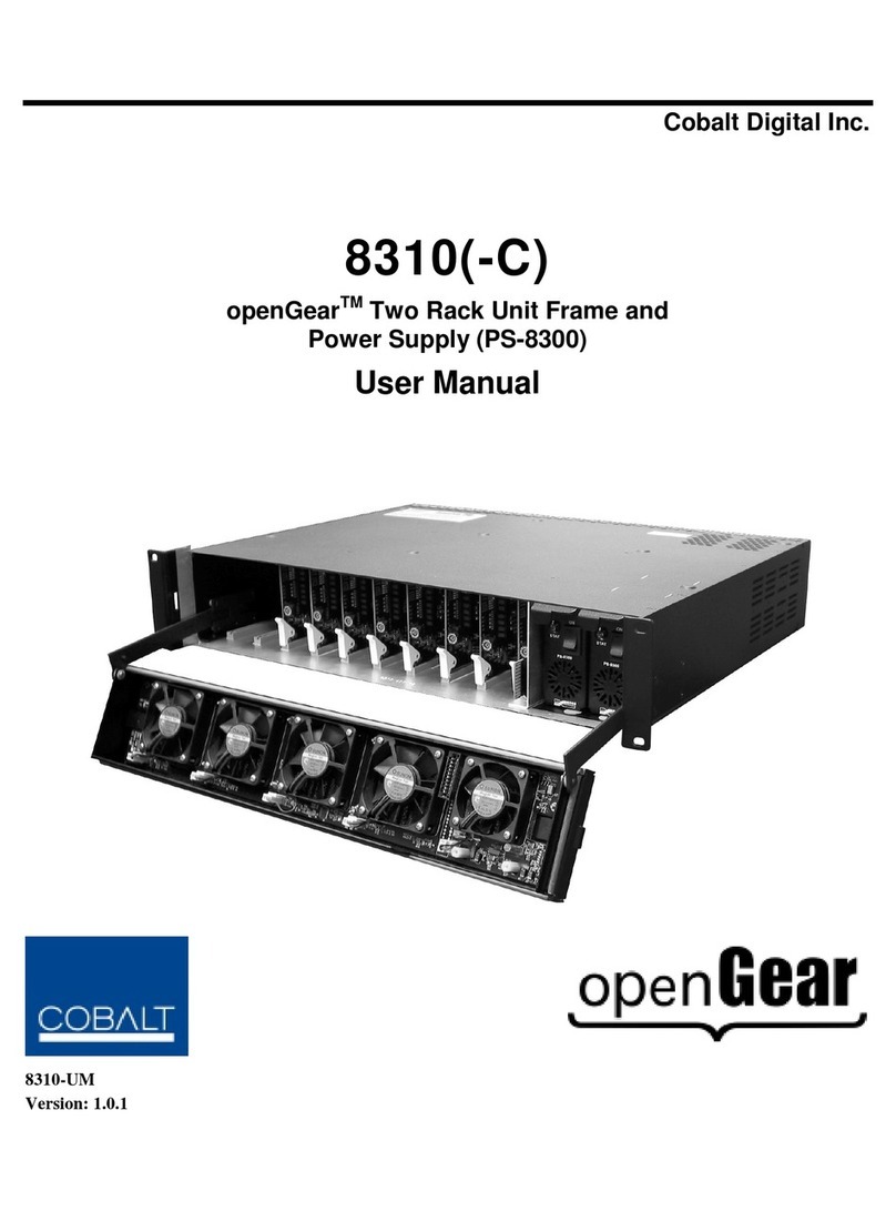
Cobalt Digital Inc OPENGEAR PS-8300 User manual

Cobalt Digital Inc

Cobalt Digital Inc OPENGEAR PS-8300 User manual

Popular Power Supply manuals by other brands

ENERMAX ETR450AWT user manual

ENERMAX

ENERMAX ETR450AWT user manual

Pepperl+Fuchs PS1000-A6-24.5 technical information

Pepperl+Fuchs

Pepperl+Fuchs PS1000-A6-24.5 technical information

Genki GK-1200 user manual

Genki

Genki GK-1200 user manual

Liebert UPStation GXT user manual

Liebert

Liebert UPStation GXT user manual

HP 712B Operating and servicing manual

HP

HP 712B Operating and servicing manual

Asus A series quick reference

Asus

Asus A series quick reference

Schaudt EBL 263-5 Operating instructions manual

Schaudt

Schaudt EBL 263-5 Operating instructions manual

Crestron GREEN LIGHT Power Switching installation guide

Crestron

Crestron GREEN LIGHT Power Switching installation guide

Lambda Vega 900 Handbook

Lambda

Lambda Vega 900 Handbook

Polk Audio SPS-1 instructions

Polk Audio

Polk Audio SPS-1 instructions

Puls QT40.481 installation manual

Puls

Puls QT40.481 installation manual

Ayre dps owner's manual

Ayre

Ayre dps owner's manual

BEL LDC120 Series Installation instruction

BEL

BEL LDC120 Series Installation instruction

Owon OWP H Series user manual

Owon

Owon OWP H Series user manual

Folio GIRO WALL user manual

Folio

Folio GIRO WALL user manual

Powerware 3110 user guide

Powerware

Powerware 3110 user guide

Gira 2120 00 operating instructions

Gira

Gira 2120 00 operating instructions

POWER USB SMART user manual

POWER USB

POWER USB SMART user manual

manuals.online logo
manuals.online logoBrands
  • About & Mission
  • Contact us
  • Privacy Policy
  • Terms and Conditions

Copyright 2025 Manuals.Online. All Rights Reserved.