Cobod BOD2-444 User manual

Instruction Manual
Original Version
BOD2-444
3D Construction Printer
Generation: 02

Instruction Manual - Original Version
Page 2 of 50
1Contents
1.1 Document version ............................................................................................................................. 4
2 Identification ............................................................................................................................................. 5
2.1 Supplier information.......................................................................................................................... 5
2.2 Declaration of Conformity................................................................................................................. 6
3 Product description ................................................................................................................................... 7
3.1 General .............................................................................................................................................. 7
3.1.1 Function description.................................................................................................................. 7
3.1.2 Machine construction................................................................................................................ 7
3.1.3 Process description.................................................................................................................. 10
3.1.4 Proper use................................................................................................................................ 10
3.1.5 Improper use ........................................................................................................................... 10
3.1.6 Modification ............................................................................................................................ 10
3.1.7 Before the commissioning....................................................................................................... 11
3.1.8 Limits of machinery ................................................................................................................. 11
3.2 Machine information....................................................................................................................... 12
3.3 Safety information........................................................................................................................... 13
3.3.1 Signs......................................................................................................................................... 13
3.3.2 Safety functions....................................................................................................................... 14
4 Definitions ............................................................................................................................................... 18
4.1 Technical terms and abbreviations ................................................................................................. 18
4.2 References....................................................................................................................................... 18
5 Handling................................................................................................................................................... 19
5.1 Transport and storage ..................................................................................................................... 19
5.2 Precautionary measures before the operation...................................Error! Bookmark not defined.
5.3 Unpacking........................................................................................................................................ 19
5.4 Safe disposal of packing material .................................................................................................... 19
5.5 Installation and assembly of the machine....................................................................................... 19
5.5.1 Mechanical assembly............................................................................................................... 19
5.5.2 Electrical installation................................................................................................................ 25
5.5.3 Connections............................................................................................................................. 26
5.6 Storage............................................................................................................................................. 26
5.7 Repacking......................................................................................................................................... 27

Instruction Manual - Original Version
Page 3 of 50
5.8 Placing of instructions ..................................................................................................................... 27
6 Operating manual.................................................................................................................................... 28
6.1 Normal function............................................................................................................................... 28
6.1.1 Connection to computer ......................................................................................................... 28
6.1.2 Manual operation.................................................................................................................... 29
6.1.3 Automatic operation ............................................................................................................... 31
6.1.4 User interface .......................................................................................................................... 31
6.2 Error situations................................................................................................................................ 37
6.3 Signals to be observed..................................................................................................................... 38
6.4 Accessories ...................................................................................................................................... 38
6.5 Disposal of waste materials............................................................................................................. 38
7 Maintenance and cleaning ...................................................................................................................... 39
7.1 Precautionary measures.................................................................................................................. 39
7.2 Maintenance made by the operator ............................................................................................... 39
7.2.1 1 –Test axis movement........................................................................................................... 40
7.2.2 2 –Test end-stops.................................................................................................................... 40
7.2.3 3 –Test Load cells.................................................................................................................... 40
7.2.4 4 –Test pump controller (OPTIONAL: only if pump controller is attached) ........................... 41
7.2.5 5 –Test all E-stops................................................................................................................... 41
7.2.6 6 –Test downwards pinch safety............................................................................................ 41
7.2.7 7 –Test safety door (Optional, if safety door is installed and connected).............................. 42
7.2.8 8 –Inspect Extruder pump ...................................................................................................... 42
7.2.9 9 –Inspect hoses ..................................................................................................................... 43
7.2.10 10 –Inspect mixing shaft......................................................................................................... 43
7.2.11 11 –Inspect cables .................................................................................................................. 43
7.2.12 12 –Grease tooth rack ............................................................................................................ 43
7.3 Maintenance and cleaning made by the cleaning personnel.......................................................... 43
7.3.1 1 –All parts of the printhead................................................................................................... 44
7.3.2 2 –Material hose..................................................................................................................... 44
7.3.3 3 –Mixer pump ....................................................................................................................... 44
7.3.4 4 –Printing area....................................................................................................................... 45
7.3.5 5 –Other equipment ............................................................................................................... 45
7.3.6 6 –Excess / waste material ..................................................................................................... 45

Instruction Manual - Original Version
Page 4 of 50
7.3.7 7 –Extruder inner parts........................................................................................................... 45
7.4 Alarm list..............................................................................................Error! Bookmark not defined.
8 Service ..................................................................................................................................................... 47
8.1 Service intervals............................................................................................................................... 47
8.1.1 1 –Maintenance task No. 1.........................................................Error! Bookmark not defined.
8.1.2 2 –Maintenance task No. 2.........................................................Error! Bookmark not defined.
8.1.3 3 –Maintenance task No. 3.........................................................Error! Bookmark not defined.
8.1.4 4 –Maintenance task No. 4.........................................................Error! Bookmark not defined.
8.1.5 5 –Maintenance task No. 5.........................................................Error! Bookmark not defined.
8.2 Customer service............................................................................................................................. 47
9 List of spare parts and consumables ...........................................................Error! Bookmark not defined.
10 Disposal of the machine ...................................................................................................................... 49
11 Logbook ............................................................................................................................................... 50
1.1 Document version
Version
Description
Date of issue
UK01
First version
November, 2018

Instruction Manual - Original Version
Page 5 of 50
2Identification
2.1 Supplier information
Manufacturer:
COBOD International A/S
Address:
Dronningens Tværgade 26
DK - 1302 København K
Phone
+45 70 60 55 33
E-Mail:

Instruction Manual - Original Version
Page 6 of 50
2.2 Declaration of Conformity

Instruction Manual - Original Version
Page 7 of 50
3Product description
3.1 General
Before the machine is commissioned, this instruction manual must be thoroughly read and
understood!
This warning symbol indicates that special precautionary measures must be taken.
If the safety precautions are not observed, it may lead to hazardous conditions and result
in personal injury or damage to property.
This symbol indicates that the following information is important.
3.1.1 Function description
This instruction manual describes the proper use of the machine.
The BOD2 is a modular gantry-based 3D construction printer. The BOD 2 printer is built from 2.5m modules
and can be built to customer specifications.
The BOD2 printer works in 3 dimensions, with the print head moving on the X-axis, the X-axis bar moving
on the Y-axis and the whole XY-group moving up and down on the 4 Z-columns. The gantry principle allows
the printer to access any position within the print envelope and gives complete freedom of movement
within the volume.
3.1.2 Machine construction
The BOD2 is designed as a stand-alone unit consisting of several integrated units and components:
• Four Z-columns (legs), height = 10 m, 4 servomotors, drivers included.
• Two Y-axis, length = 10 m, 2 servomotors, drivers included.
• One X-axes, width = 10 m, 1 servomotor, drivers included.
• One print head, 2 servomotors, drivers included.
(One for turning the nozzle and one for controlling the material flow)
• Control cabinet with supply disconnector, electrical equipment, 3D print controller and safety PLCs.

Instruction Manual - Original Version
Page 8 of 50
Figure 1: Model of printer
Instruction Manual - Original Version
Page 9 of 50
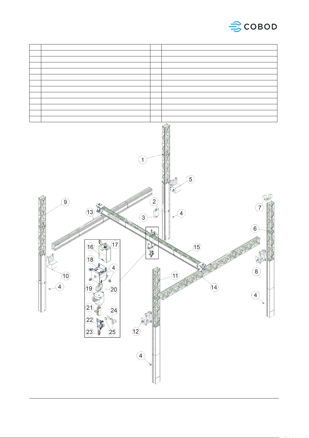
Figure 2: Exploded view, printer parts
1
Z1-axis
14
Y2-axis
2
Main E-box
15
X-axis
3
Power connection and circuit breaker
16
X-carriage E-Box
4
Emergency stop
17
Status lamp
5
Z1-carriage
18
X-carriage
6
Z2-axis
19
Material hopper
7
Hose management
20
Mixing shaft
8
Z2-Carriage
21
PCP
9
Z3-axis
22
U Axis
10
Z3-carriage
23
Nozzle
11
Z4-axis
24
Camera Mount
12
Z4-carriage
25
IP Cameras
13
Y1-axis

Instruction Manual - Original Version
Page 10 of 50
3.1.3 Process description
The machine is intended for automated extrusion of concrete materials in layers. The shape of the layers is
directed by a predefined digital model.
•Fresh concrete or mortar is fed to the hopper. Either manually or by an external pumping device.
•From the hopper, the concrete is extruded through a nozzle, and placed in a predefined layer
pattern.
•Layers are applied on top continuously until the desired geometry is printed.
•The machine can be controlled manually or automatically.
3.1.4 Proper use
The machine may only be used under the operating conditions foreseen in this instructions manual.Any
other use beyond such operating conditions is deemed not conform to the instructions manual and the
manufacturer cannot accept any liability what-so-ever for subsequent loss or damage.
Proper use shall be deemed to include:
•The observance of all references of this instruction manual.
•The observance of service intervals and maintenance routines.
3.1.5 Improper use
The manufacturer / supplier will not be liable for any subsequent loss or damage resulting from improper
use of the machine.
Improper use shall be deemed to include:
•The use of substances that may damage machine parts. Including substances that may create
explosive or poisonous gases posing a risk to personnel or property.
•Improper or missing maintenance of the machine.
•Improper installation of machine or its sub-components.
•Use of the machine for other operations than the stated purpose.
3.1.6 Modification
Any alterations or additions to the machine must be filed in the technical documentation of the machine. If
necessary, the Declaration of Conformity must be updated and signed again. The responsibility for this rests
with the owner of the machine.

Instruction Manual - Original Version
Page 11 of 50
3.1.7 Before the commissioning
Before the commissioning of the machine, it must be checked that all parts have been installed according
to the documentation and instructions from COBOD International A/S.
Before the commissioning of the machine, all relevant personnel must be instructed in the documentation
of the machine –including instruction manual, maintenance instructions, diagrams etc.
3.1.8 Limits of machinery
3.1.8.1 Use limits
The BOD2 is intended for use on construction sites and will be
installed inside (typically in a tent).
•3D print of objects within the dimensions of the machine.
•Automatic mode used to move the machine based on G-code.
•The machine can be operated manually.
•The machine is operated from a web interface or from a touch panel.
•The supply disconnector is installed outside of the operating area of the machine.
•Energy supply: see Power Sources.
3.1.8.2 Space limits
The foot print of the BOD2 444 is:
•Length = 10.1 m.
•Width = 12.6 m
•Height = 10.5 m.
3.1.8.3 Time limits
The service life of the machine is 20 years of a daily 8-hour operation. This is based on the presumption that
all service and maintenance instructions described in this instruction manual are observed carefully.
3.1.8.4 Other limits
The BOD2 is intended for use on construction sites and must be installed inside (typically in a tent).
Printing material is a premix of concrete and cement-based mortars.
Temperature limits: 5 °C to +50 °C.

Instruction Manual - Original Version
Page 12 of 50
3.2 Machine information
Description
Unit
Value
Measurements (length x width x height)
[m]
10.1 x 12.6 x 10.5
Weight
[kg]
5023
Power consumption
[A]
32
Voltage
[V]
3x400VAC + PE
Frequency
[Hz]
50/60 Hz
Short circuit current, Ikmin
[A]
500
Short circuit current, Ikmax
[A]
1200
Max. speed (X –Axis)
[mm/s]
250
Max. speed (Y –Axis)
[mm/s]
250
Max. speed (Z –Axis)
[mm/s]
50
Sound level
[dB(A)]
Less than 70
Required bed plate flatness
[mm/m]
10 mm/m

Instruction Manual - Original Version
Page 13 of 50
3.3 Safety information
3.3.1 Signs
The machine is fitted with several mandatory and warning signs. The meaning of these is described in the
following.
Protection
Description
Symbol
Helmet
Mandatory:
When entering the printing area.
When working in the area, always wear approved
safety helmet.
Safety shoes
Mandatory:
When entering the printing area.
When working in the area, always wear approved
safety shoes
Safety glasses
Mandatory:
When working with fresh concrete or dry mix
concrete in- or outside printing area
Protective gloves
Mandatory:
When working with fresh concrete or dry mix
concrete in- or outside printing area
Respiratory protection
Mandatory:
When working with fresh concrete or dry mix
concrete in- or outside printing area
Electricity
Warning:
Control Cabinets.
Only experienced and skilled personnel may open
the control cabinets.
Crushing of hands
Warning:
Transmission parts, toothed rack on each axis.
Crushing
Warning:
When moving the X-, Y- axis and print head
downwards, between print head and floor.
When print head is moved towards one of the two
“end” positions on the X-axis.

Instruction Manual - Original Version
Page 14 of 50
3.3.2 Safety functions
Before operating the machine, the operator must seek information about the safety functions and
protection equipment of the machine.
The use and operation of the machine must only be initiated when all safety functions
are fully present and in an operable condition!
Defective safety functions and protection equipment may lead to loss of safety and
hazardous situations.
In case defective safety functions and protective equipment is found, do the following:
•Stop the machine immediately.
•Make sure the machine cannot restart by disconnecting the supply sources to the
machine.
The following safety and protection devices are installed on the machine:
Emergency stop-function
The emergency stop function is a supplementary safety function, with the purpose of preventing a source of hazard
from arising caused by the improper use of the machine. As an example, a source of hazard could result in personal
injury, damage to the machine or ongoing work, or it may arise because another safety function is failing.
After actuation and before disengaging the E-stop devices, the machinery shall be inspected in order to detect the
reason for actuation.
Components included in the safety function.
Input part
Logical part
Output part
Emergency stop push-button
(E-stop)
The emergency stop push-button is
shaped like a red push-button
switch on a yellow background.
Emergency stop of the machine is
induced by activating the
emergency stop push-button.
The emergency stop push-buttons
are located at the following places
of the machine:
-One on each leg (Z-axis).
-Three on the print head.
-One at the control panel.
-One on safety door
Disengagement of the E-stop push
button:
-Turn the red push button
counter clockwise.
Safety controller.
Intelligent controller monitoring
the safety function.
The service life of the safety
controller is 20 years.
The safety function i.e. the
machine must not be used beyond
20 years. The use beyond 20 years
is conditional to the fact that the
relevant components are replaced
by new components of identical or
improved properties than the
original ones.
The safety controllers are located
in the control cabinets.
Servo drives.
Disconnects the power supply to the
moving parts.
-X-axis (front-, back- ward);
-Y-axes (up-, down-ward);
-Print head (Side wards);
-Mixer in the print head.
-Rotation of the print head.
The service life of the servo drives is
20 years.
The servo drives are located in the
control cabinet.

Instruction Manual - Original Version
Page 15 of 50
Displays and alarms
When activating an E-stop, the status will appear on the operator monitor:
”Emergency stop of the machine is activated”
Operating conditions
The work of the emergency function is unchanged throughout any operation modes of the machine.
Maintenance and test
The emergency stop function must be activated and tested before commissioning after each installation or
reinstallation of the machine.
Test: Activating the E-stop one at the time, must stop all servo drives.
As a minimum, the emergency stop function must be visually checked and activated at least every 6 months.
Also see section 7 of this instruction manual.
The safety function complies with EN ISO 13849-1:2015.
The emergency stop function is constructed as a Category 3, PL d.
Speed monitoring of the movement of the X –axis and the Print head (optional)
The speed monitoring of the movement of the X –axis and the print head is a safety function, with the purpose of
preventing them going faster than 250 mm/sec. If the limit is exceeded, the machine is stopped.
The speed monitoring is optional and comes together with the perimeter guarding which also is optional.
If the application requires a speed higher than 250 mm/sec. for the X-axis and print head, the perimeter guarding
together with an interlocked door must be installed. When entering the guarded zone, opening the interlocked
door, the speed of the X-axis and the print head is automatically reduced to 250mm/sec and is then monitored by
the speed monitoring as long as the door to the guarded zone is open. As soon as the door is closed the speed is
automatically increased. See also Interlocked door.

Instruction Manual - Original Version
Page 16 of 50
Components included in the safety function.
Input part
Logical part
Output part
Encoder.
If the speed limit of 250mm/sec is
exceeded by the X-axis or the print
head, the machinery is stopped.
The encoders are located at/on the
drive for the X-axis and on the drive
for the Print head.
Safety controller.
Intelligent controller monitoring the
safety function.
The service life of the safety
controller is 20 years.
The safety function i.e. the machine
must not be used beyond 20 years.
The use beyond 20 years is
conditional to the fact that the
relevant components are replaced by
new components of identical or
improved properties than the
original ones.
The safety controllers are located in
the control cabinets.
Servo drives.
Disconnects the power supply to the
moving parts.
-Y-axis (Up-, Down wards);
-X-axis (For-, Back- wards);
-Print head (Sidewards);
-Mixer in the print head.
-Rotation of the print head.
The service life of the servo drives is
20 years.
The servo drives are located in the
control cabinet.
Displays and alarms
When the door is open, the status will appear on the operator monitor:
”Door open, running with reduced speed”
Operating conditions
Works:
-only together with perimeter guarding and interlocked door;
-in automatic and manual mode when interlocked door is open.
Maintenance and test
The encoders must be tested before commissioning, after each installation or reinstallation of the machine.
Test by opening the door, speed must be reduced to 250 mm/sec. When door is closed, speed is increased.
As a minimum, the encoders function must be visually checked and activated at least every 6 months.
Also see section 7 of this instruction manual.
The safety function complies with EN ISO 13849-1:2015.
The speed monitoring function is constructed as a Category 3, PL d.
Interlocked door, perimeter guarding (optional, speed > 250mm/sec.)
This safety function is to protect the operator against the hazardous fast moving parts (Speed > 250mm/sec), the
X-axis and the movement of the print head.
The perimeter guarding is optional and comes together with the speed monitoring, which also is optional.

Instruction Manual - Original Version
Page 17 of 50
If the application requires a speed higher than 250 mm/sec. for the X-axis and print head, the perimeter guarding
together with an interlocked door must be installed. When entering the guarded zone, opening the interlocked
door, the speed of the X-axis and the Print head is automatically reduced to 250mm/sec and is then monitored by
the speed monitoring as long as the door to the guarded zone is open. As soon as the door is closed the speed is
automatically increased.
Components included in the safety function
Input part
Logical part
Output part
Interlock.
The Interlock is an electrical safety
device.
The safety device may be coded to
prevent bypassing.
The safety device is installed on the
doors to the guarded zone:
Safety controller.
Intelligent controller monitoring the
safety function.
The service life of the safety
controller is 20 years.
The safety function i.e. the machine
must not be used beyond 20 years.
The use beyond 20 years is
conditional to the fact that the
relevant components are replaced by
new components of identical or
improved properties than the
original ones.
The safety controllers are located in
the control cabinets.
Servo drives.
Reduces the speed on the following
moving parts.
-X-axis (For-, Backwards);
-Print head (Sidewards);
The service life of the servo drives is
20 years.
The servo drives are located in the
control cabinet.
Displays and alarms
When the door is open, the status will appear on the operator monitor:
”Door open, running with reduced speed”
Operating conditions
The safety function operates unchanged in any operating conditions of the machine.
Maintenance and test
The safety function must be activated and tested before commissioning after each installation or reinstallation of
the machine.
Test by opening the door, speed must be reduced to 250 mm/sec. When door is closed, speed is increased again.
As a minimum, the safety function must be visually checked and activated at least once a day.
Also see section 7 of this instruction manual.
The safety function complies with EN ISO 13849-1:2015.
The speed monitoring function is constructed as a Category 3, PL d.

Instruction Manual - Original Version
Page 18 of 50
4Definitions
4.1 Technical terms and abbreviations
In the following, the technical terms and abbreviations used in this instruction manual are described.
Terms
Explanation
Instructed person
A person having received the necessary training to carry out a task in a safe and
responsible way
3DCP
3D Concrete Printing
Print head
The device that attached on the carriage, handles extrusion and depositioning of
material
Nozzle
The small piece that sits on the end of the print head, that shapes the final form of
the extruded material. Can be 3D printed or machined.
Origo
The starting position of the printer, defined as [X,Y,Z,E,U] = [0,0,0,0,0]
4.2 References
1. Mixing/pumping equipment M-tec duo mixer. https://m-tec.com
2. Hilti HIT-Z anchors
https://www.hilti.dk/medias/sys_master/documents/h1c/h4b/9330166333470/Instruction-for-
use-HIT-RE-500-V3-Instruction-for-use-PUB-5307431-000.pdf
3. G-code documentation https://duet3d.dozuki.com/Wiki/G-code
4. Duet3D documentation, firmware updates, maintenance, etc. - https://duet3d.dozuki.com/

Instruction Manual - Original Version
Page 19 of 50
5Handling
This section describes how the machine is to be operated in various situations. Where specific personal
qualifications are required, this will be described.
Installation and dismounting of the machine must be carried out by qualified and trained personnel. To
prevent accidents, all safety instructions must be observed.
5.1 Transport and storage
The machine is built of components from various suppliers. Some of these parts are of a size, shape and
weight that require special handling. Follow the instruction manual from the manufacturer or supplier on
how to apply lifting equipment and the appropriate lifting points.
Only instructed and certified personnel have the permission to move machine parts using a
fork lift truck or crane.
Only appropriate and certified equipment must be used for the lifting of machine parts.
5.2 Unpacking
When unpacking the machine, it is to be controlled if damage to the machine has occurred during
transport. Damage affecting the functionality or safety of the machine must be repaired before the
machine is put into operation.
5.3 Safe disposal of packing material
Packing material consists of:
-120x120x1500mm wooden joists
-EU Pallets (120x80 cm)
Both are reusable items and should not be disposed of, unless damaged. If damaged or unusable, dispose
as wooden waste according to local law.
5.4 Installation and assembly of the machine
5.4.1 Mechanical assembly

Instruction Manual - Original Version
Page 20 of 50
To ensure the safe intended use of the printer, it needs to be installed and assembled according to the
following instructions.
Steps for installation:
1. Mapping and Anchoring
4. Mounting X-Axis
2. Mounting Z-Axes
5. Connecting cables
3. Mounting Y-Axes
5.4.1.1 Mapping and Anchoring
This section covers installation of Anchors, serving as a base for securing Z axes to the ground plane. The
procedure involves precisely mapping and marking where the anchors will be placed, drilling holes and
securing anchors with glue. Protective gear (gloves/mask/safety glasses) is required for drilling and while
handling Hilti glue.
Tools needed
•16 x Hilti HIT-Z anchors
M16x240
•1 x Laser measuring
device
•1 x Angular laser
•1 x Marker Pen
•1 x Hammer Drill
•1 x M8 Concrete drill bit
•1 x M18 Concrete drill bit
•1 x 3D printed drill guide
Table of contents


