manuals.online logo
Brands
  1. Home
  2. •
  3. Brands
  4. •
  5. Cobra
  6. •
  7. Bicycle Accessories
  8. •
  9. Cobra 602-2004 User manual

Cobra 602-2004 User manual

®23801 E. La Palma Ave., Yorba Linda, Ca 92887 Ph. 714.692.8180 Fax. 714.692.5016
www.cobrausa-hd.com
04/17 ®
*Cobra®recommends you always wear a helmet while riding. Please never operate your motorcycle while under
the influence of alcohol and/or drugs. Enjoy the new look of your motorcycle and please ride safely.
Items Supplied >
1 - Sissy Bar w/ Pad and Chrome Insert
2 - Mount Brackets (Left/Right)
2 - Detachable Side Plates (Left/Right)
2 - Front Mounting Bushings
2 - 3/8”-16 x 2” Buttonhead Bolts
4 - M8 x 20mm Buttonhead Bolts
Application(s) >
HARLEY:
FXD SUPERGLIDE 06-10
FXDB STREET BOB 06-17
FXDC SUPERGLIDE CUSTOM 06-14
FXDL LOW RIDER 06-09, 14-17
Instruction Manual >
Read all instructions carefully before installing your new Cobra®product!
1. If the motorcycle is equipped with rear reflectors than they must be removed along with any remaining
adhesive left on the motorcycle. Save the reflectors for reuse.
2. Apply masking tape to the fenders above the fender rail to protect the paint during installation. See
FIGURE 1.
3. Remove the front bolt from the right side fender rail and discard. NOTE: Remove one side only so the
fender does not fall resulting in possible scratches or damage to the fender or paint. See FIGURE 1.
4. Loosen the rear bolt securing the fender and rear turn signal from the inside of the fender until there is
enough space to insert the mount bracket. The rear hole in the mount bracket is slotted so it can slide
over the rear bolt so it does not need to be removed completely. See FIGURE 1.
5. Pull the front of the inner nut plate away from the inside of the fender to allow clearance to insert the
front of the mount bracket. The boss on the front of the nut plate will insert through the large hole on
the front of the mount bracket. See FIGURE 2.
602-2004/602-2004B
Page 1 of 4
DOCUMENT NO. 0017 REV. B
FIGURE 1
APPLY MASKING TAPE
TO PROTECT PAINT
REMOVE FRONT
BOLT
LOOSEN TURN
SIGNAL BOLT ON
INSIDE OF FENDER
CONTINUED ON PAGE 2
®23801 E. La Palma Ave., Yorba Linda, Ca 92887 Ph. 714.692.8180 Fax. 714.692.5016
www.cobrausa-hd.com
04/17 ®
Instruction Manual >
602-2004/602-2004B
Page 2 of 4
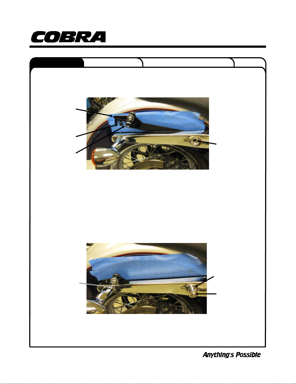
6. Install the right mounting bracket between the fender rail and fender (part # facing inward). The boss
on the front of the nut plate will insert through the large hole on the front of the mount bracket. The
rear of the mount bracket is slotted to slide over the rear turn signal bolt and over the turn signal
wiring. See FIGURE 2.
7. Align the front boss on the nut plate with the front hole of the mounting bracket and push the nut plate
outward to seat it against the inner fender and into the frame rail. See FIGURE 2.
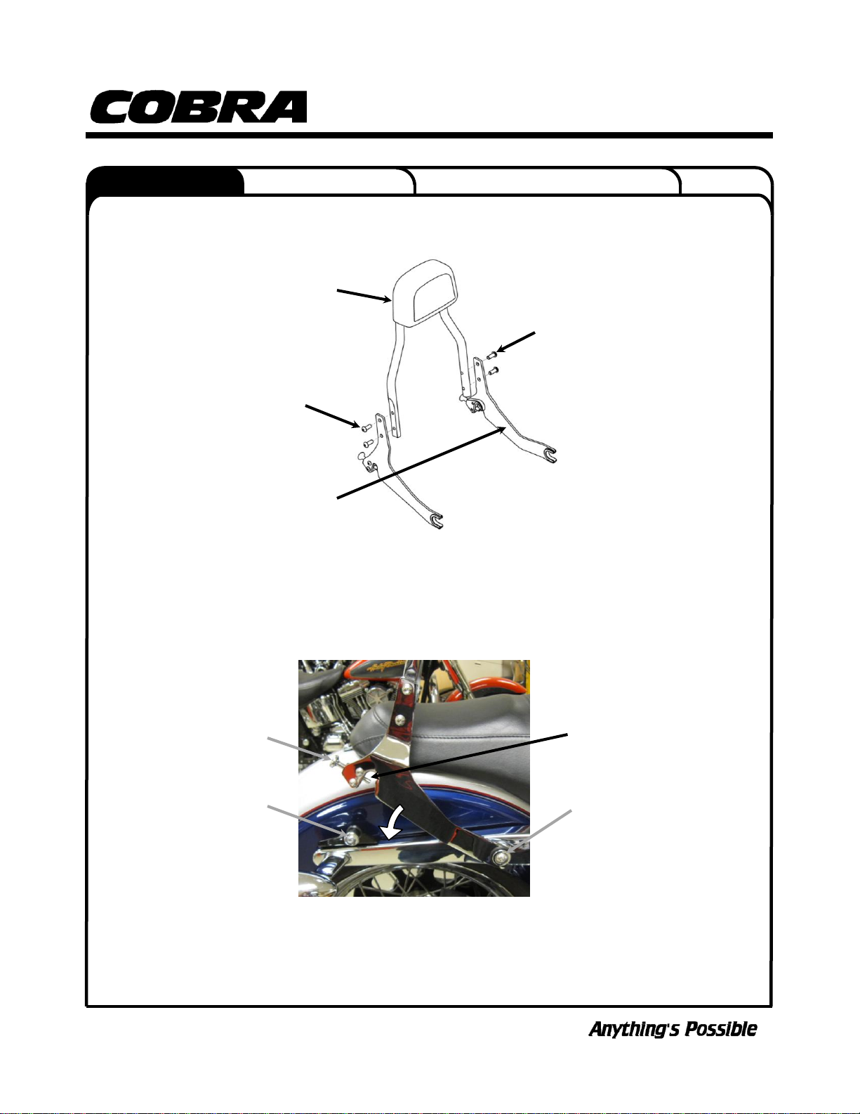
8. Insert the 3/8-16 x 2” button head bolt through the supplied front mounting bushing, through the front
frame rail hole, through the mount bracket and into the inner nut plate. Snug the bolt making sure the
front boss of the nut plate inserts through the hole in the mount bracket and into the frame rail. DO
NOT TIGHTEN front bolt at this time. See FIGURE 3.
9. Push down on the rear of the mount bracket to make sure it is aligned with the rear turn signal bolt
and tighten the bolt. Make sure the turn signal wire is going through the clearance hole in the mount
bracket and is not getting pinched. See FIGURE 3.
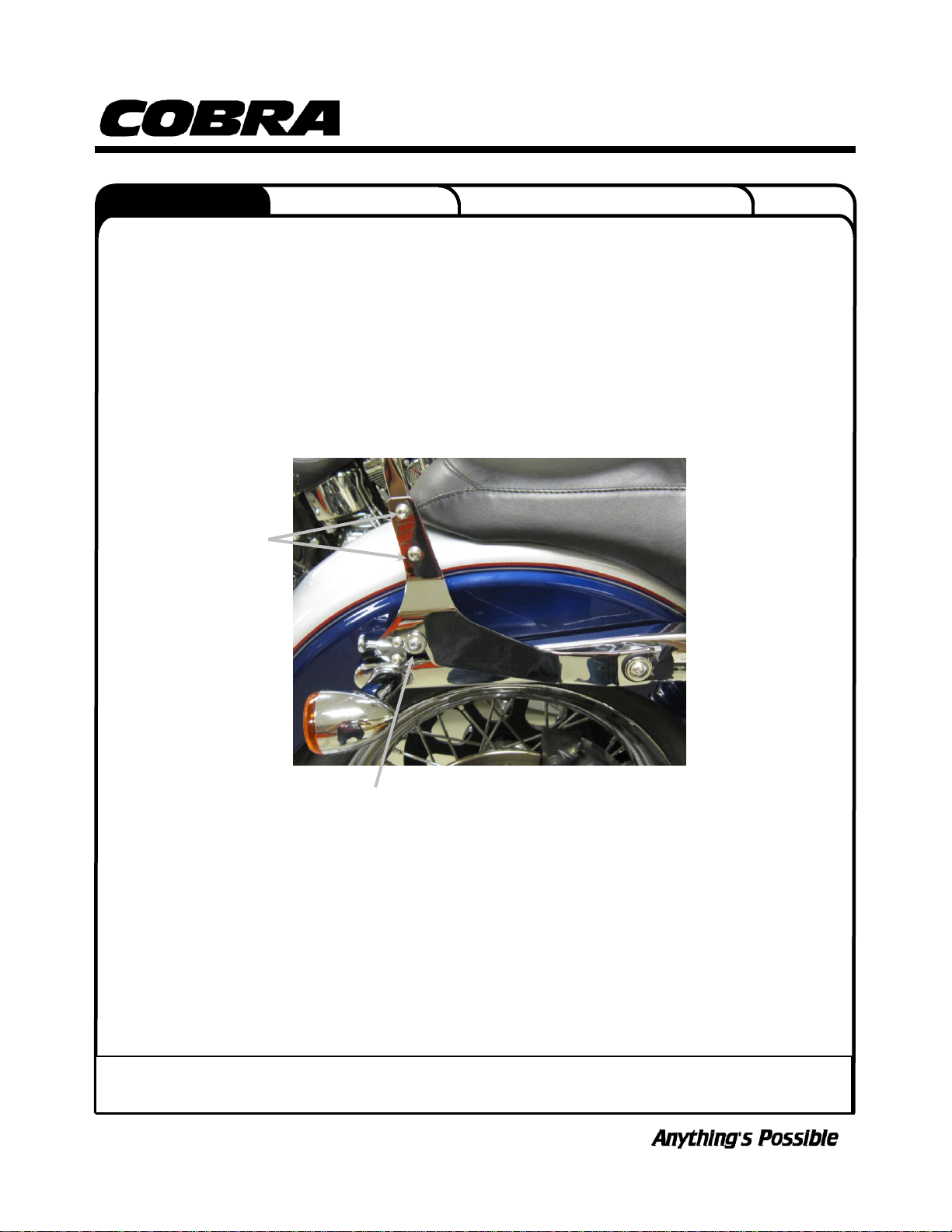
10. Tighten the front bolt securing the front mounting bushing.
11. Repeat Steps 2–10 on the left side.
DOCUMENT NO. 0018 REV. A
FIGURE 3
MAKE SURE NOT TO
PINCH TURNSIGNAL
WIRES
FRONT MOUNT
BUSHING
3/8-16 X 2”
BUTTONHEAD
BOLT
FIGURE 2
SLOT FOR TURN
SIGNAL BOLT
SLOT FOR TURN
SIGNAL WIRES
ALIGN FRONT HOLE
OF BRACKET WITH
FRONT HOLE OF
FRAME RAIL
RIGHT SIDE
MOUNT BRACKET
CONTINUED ON PAGE 3
®23801 E. La Palma Ave., Yorba Linda, Ca 92887 Ph. 714.692.8180 Fax. 714.692.5016
www.cobrausa-hd.com
04/17 ®
Instruction Manual >
602-2004/602-2004B
Page 3 of 4
12. Install the supplied side plates on to the sissy bar with the four M8 X 20mm button head bolts. Make
sure the u-shaped grommets are facing the same direction as the sissy bar pad and the part numbers
are facing inward. See FIGURE 4. Snug the bolts but DO NOT TIGHTEN at this time.
13. Install the sissy bar onto the bike by first inserting the front portions of the side brackets on to the front
mounting bushings on the frame rails. Make sure the sissy bar is seated all the way onto the mounting
bushings. See FIGURE 5.
14. Then slowly rotate the sissy bar downward so the rear portions of the brackets slip over the rear
mounting bushings. See FIGURE 5.
DOCUMENT NO. 0018 REV. A
FIGURE 4
PART NUMBER
FACING INWARD
M8 X 20mm
BUTTONHEAD
BOLTS
M8 X 20mm
BUTTONHEAD
BOLTS
SISSY BAR
PAD
CONTINUED ON PAGE 4
REAR MOUNTING
BUSHING
FRONT MOUNTING
BUSHING
DETACHABLE
LATCH KNOB
DETACHABLE
LATCH PIN
FIGURE 5
®23801 E. La Palma Ave., Yorba Linda, Ca 92887 Ph. 714.692.8180 Fax. 714.692.5016
www.cobrausa-hd.com
04/17 ®
Instruction Manual >
602-2004/602-2004B
Page 4 of 4
15. Pull backward on both detachable latch knobs and then push downward on the backrest to allow the
backrest to sit completely on the rear mounting bushings. Then release the detachable latch knob to
fully engage the latch pin underneath the mounting kit bushing. See FIGURE 6.
16. Always check to make sure both detachable latch pins are fully engaged on the bottom of the
mounting kit bushing. Failure to fully engage the detachable latch pin could cause the backrest to
come loose while riding. See FIGURE 6.
17. Pull backward on the top of the sissy bar and then tighten all four M8 X 20mm bolts. See FIGURE 6.
18. Before each ride, check to make sure the detachable latches are fully engaged underneath the
mounting bushings.
19. Check the tightness of all the screws after the first ride and after the first 500 miles.
DOCUMENT NO. 0018 REV. A
MAKE SURE LATCH PIN
IS FULLY ENGAGED
UNDER BUSHING
FIGURE 6
TIGHTEN ALL FOUR
M8 X 20mm BOLTS
To clean your black accessory use a liquid based soap detergent, such as dishwashing soap applied with a soft cloth and
rinse with clean water. Note: Avoid abrasive cleaning methods such as granular or dry cleansers, simple green, Scotch-
Brite or steel wool pads. Abrasives may breach the coating and shorten life.

This manual suits for next models

1

Popular Bicycle Accessories manuals by other brands

Holux GPSport 260 quick guide

Holux

Holux GPSport 260 quick guide

Unior 1693BS-US manual

Unior

Unior 1693BS-US manual

Gemini TITAN manual

Gemini

Gemini TITAN manual

K-Edge K13-050 Technical spesification

K-Edge

K-Edge K13-050 Technical spesification

Ergon GXR Installation and user instructions

Ergon

Ergon GXR Installation and user instructions

Bosch Intuvia eShift Supplement to original operating instructions

Bosch

Bosch Intuvia eShift Supplement to original operating instructions

Bosch Active Line Original operating instructions

Bosch

Bosch Active Line Original operating instructions

Shimano RD-M662 Service instructions

Shimano

Shimano RD-M662 Service instructions

Hyena DP-A250+ product manual

Hyena

Hyena DP-A250+ product manual

Allegion AXA Niteline DE instruction manual

Allegion

Allegion AXA Niteline DE instruction manual

Easton Sports headset Adjuster BearTrap instruction manual

Easton Sports

Easton Sports headset Adjuster BearTrap instruction manual

moon COMET-X PRO User guideline

moon

moon COMET-X PRO User guideline

CD CDC6 instructions

CD

CD CDC6 instructions

Thule coaster xt instructions

Thule

Thule coaster xt instructions

Minshine T154-1 user guide

Minshine

Minshine T154-1 user guide

Rose electronics airik MT-HP owner's manual

Rose electronics

Rose electronics airik MT-HP owner's manual

Hepha Trekking 7 instructions

Hepha

Hepha Trekking 7 instructions

MSW JETSTREAM INFLATOR HEAD quick start guide

MSW

MSW JETSTREAM INFLATOR HEAD quick start guide

manuals.online logo
manuals.online logoBrands
  • About & Mission
  • Contact us
  • Privacy Policy
  • Terms and Conditions

Copyright 2025 Manuals.Online. All Rights Reserved.