2
Installation
© Moffat Ltd, September 2008
3
Revision 1
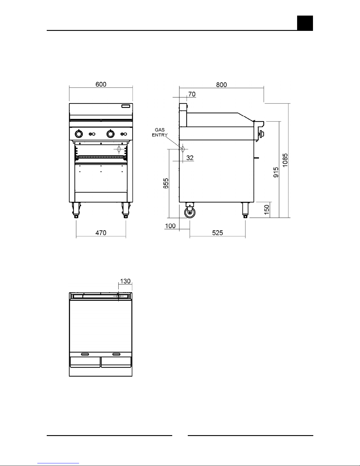
Cobra Series CT6 Gas Griddle Toaster
Installation Requirements
NOTE:
• It is most important that this appliance is installed correctly and that operation is
correct before use. Installation shall comply with local electrical, gas, health and
safety requirements.
• This appliance shall be installed with sufficient ventilation to prevent the occurrence
of unacceptable concentrations of health harmful substances in the room, the
appliance is installed in.
Cobra Griddle Toasters are designed to provide years of satisfactory service and correct installation is essential to
achieve the best performance, efficiency and trouble-free operation.
This appliance must be installed in accordance with National installation codes and in addition, in
accordance with relevant National / Local codes covering gas and fire safety.
Australia: - AS5601 - Gas Installations.
New Zealand: - NZS5261 - Gas Installation.
United Kingdom: - Gas Safety (Installation & Use) Regulations 1998.
- BS6173 - Installation of Catering Appliances.
- BS5440 - 1 & 2 Installation Flueing & Ventilation.
Ireland: - IS 820 - Non Domestic Gas Installations.
Installations must be carried out by qualified service persons only. Failure to install equipment to relevant codes
and manufacturers specifications shown in this section will void the warranty.
Components having adjustments protected (e.g. paint sealed) by the manufacturer, are only allowed to be
adjusted by a qualified service person. They are not to be adjusted by the installation person.
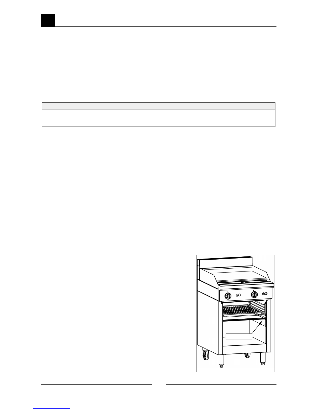
Unpacking
• Remove all packaging and transit protection from the appliance including all protective plastic coating
from the exterior stainless steel panels.
• Check equipment and parts for damage. Report any damage immediately to the carrier and distributor.
• Report any deficiencies to the distributor who supplied the appliance.
• Check that the available gas supply is correct to that shown on the rating plate located on the right hand
inner side panel.
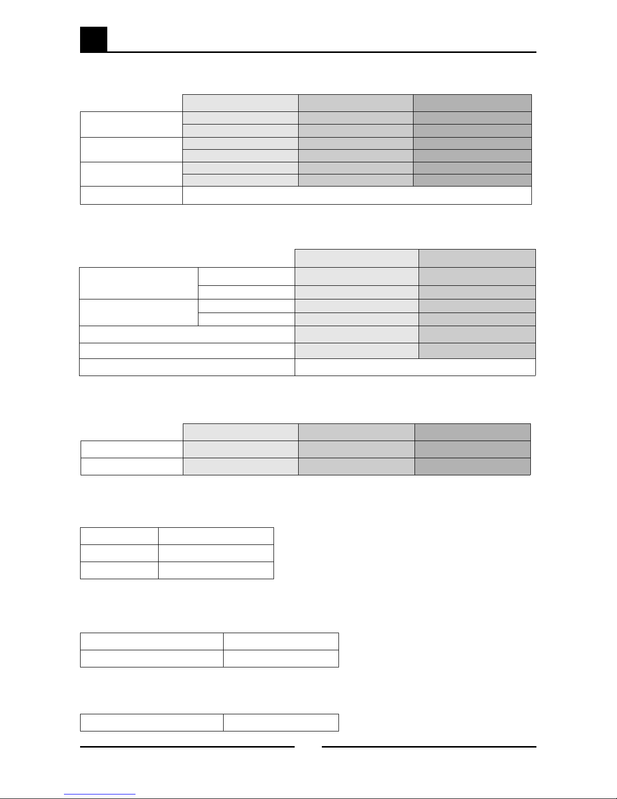
• Check that the following parts have been supplied with the appliance:
Enamelled Crumb Tray 1.
Toasting Rack 1.
Toasting Rack Tray (St/Steel) 1.
Grease Drawer 1.
Adjustable Legs 4.
Gas Regulator 1.
Alternate Gas Conversion Kit 1.
Location
1. Installation must allow for a sufficient flow of fresh air for the combustion air supply.
Combustion Air Requirements:
Natural Gas (G20) 10 m³/hr.
LPG (G31) 9 m³/hr.
Town Gas 10 m³/hr.
2. Installation must include adequate ventilation means, to prevent dangerous build up of combustion
products.
3. Position the appliance in its approximate working position.
4. All air for burner combustion is supplied from underneath the appliance. The legs must always be fitted
and no obstructions placed on the underside or around the base of the appliance, as obstructions will
cause incorrect operation and / or failure of the appliance.