Cobra LT108MSL User manual

1
COBRA GARDEN TRACTOR
OWNER’S MANUAL
MODEL: LT108MSL (TTM108S)
LT108HSL (TTM108SH)
WARNING!
When using the machine the safety rules must be followed. For your own safety and bystanders please read these
instructions before operating the machine. Please keep the instructions safe for later use.
Cobra Garden Machinery
Henton and Chattell Ltd., London Road, Nottingham NG2 3HW UK
www.cobragarden.co.uk

2
INTRODUCTION
Dear Customer,
Thank you for choosing a Cobra garden machinery product.
This manual has been written to help you become familiar with the machine and use it safely and efficiently. Do not
forget that it is an integral part of the machine, so keep it close at hand for future reference and pass it on to the
purchaser if you sell the machine.
The garden tractor has been designed and built in compliance with current standards, and is safe and reliable when
used for cutting and collecting grass following the instructions in this manual. Always follow the instructions to
ensure safe operation. If you use the machine in any other way or ignore the instructions for safe use, maintenance
and repair, it is considered "incorrect usage". In this case, the warranty is automatically voided and the
manufacturer will not be held responsible for damage or injury to yourself or others.
We continuously improve our products and as such minor modifications may result in slight differences between your
garden tractor and the instruction manual. Modifications can be made to the machine without notice and without the
obligation to update the manual, although the essential safety and function characteristics will remain unaltered. If in
doubt, do not hesitate to contact your dealer. And now enjoy your Cobra garden tractor.
AFTERSALES SERVICE
This manual gives all the necessary instructions for using the machine and carrying out basic maintenance.
Any adjustments or maintenance operations not described in this manual must be carried out by your
dealer or a specialised Service Centre. Both have the necessary knowledge and equipment to ensure that
the work is done correctly without affecting the safety of the machine.
This will help you keep your new purchase in peak performance and maintain its value over time.
For any replacement parts, contact your Cobra dealer.
WARNING LABELS

3
IMPORTANT
The lawnmower must always be used with utmost caution. So that safety precautions and operating instructions are
always readily on hand, labels have been affixed to the machine showing pictographs illustrating the main operating
precautions. The labels, according to applicable safety standards, are considered an integral part of the machine,
the user is therefore responsible for replacing them in the event they become detached or illegible.
LABEL POSITION

4
TABLE OF CONTENTS
1.
SAFETY............................................................................................................................5
2.
IDENTIFICATION
OF
THE
MACHINE
AND
COMPONENTS
.............................................9
3.
UNPACKING AND ASSEMBLY..........................................................................11
4.
CONTROLS AND INSTRUMENTS........................................................................... 17
5.
HOW TO USE THE MACHINE.................................................................................. 20
5.1
SAFETY RECOMMENDATIONS......................................................................... 20
5.2
WHY THE SAFETY DEVICES CUT IN............................................................... 20
5.3
DIRECTIONS BEFORE STARTINGWORK...................................................... 20
5.4
USING THE MACHINE......................................................................................... 22
5.5
USING ON SLOPING GROUND ......................................................................... 25
5.6
TRANSPORTING................................................................................................... 26
5.7
LAWN MAINTENANCE......................................................................................... 26
6.
MAINTENANCE........................................................................................................... 27
6.1
SAFETY RECOMMENDATIONS......................................................................... 27
6.2
SCHEDULED MAINTENANCE............................................................................ 28
6.3
CHECKS AND ADJUSTMENTS.......................................................................... 29
6.4
DISMANTLING AND REPLACEMENT ............................................................... 29
6.5
LUBRICATION........................................................................................................ 31
7.
TROUBLESHOOTING................................................................................................ 32
8.
SPECIFICATION.......................................................................................................... 35
9.
WARRANTY................................................................................................................. 36
10.
EC DECLARATION................................................................................................... 38

5
IMPORTANT
1. SAFETY
1.1HOW TO READ THE MANUAL
Some paragraphs in the manual containing important information regarding safety and operation are emphasised in
the following ways.
or These give details or further information on what has
already been said, in the aim to prevent damage to the machine.
Non-observance will result in the risk of injury to oneself or others
Non-observance will result in the risk of serious injury or death to oneself or others
Positions refer such as “front”, “back”, “left” or “right” hand side, refer to forward travel direction.
For all operations regarding the use and maintenance of the engine not described in this manual,
refer to the relevant manuals which form an integral part of all the documentation supplied with
the machine.
1.2 GENERAL SAFETY REGULATIONS
Read carefully before using the machine.
A) TRAINING - Read the instructions carefully.
Be familiar with the controls and how to use the equipment properly.
–Never let children or people unfamiliar with these instructions use the machine. Local regulations can restrict
the age of the user.
–Never mow while people, especially children, or pets arenearby; Never mow while dark.
–Keep in mind that the operator or user is responsible for accidents or hazards occurring to other people or
their property.
–Do not carry passengers.
–All drivers should seek and obtain professional and practical instruction. Such instruction should emphasise:
–the need for care and concentration when working with ride-on machines;
–you cannot use the brake to regain control of a ride-on machine sliding down a slope.
The main reasons for loss of control are:
–insufficient wheel grip;
–over-speeding;
–inadequate braking;
–the type of machine is unsuitable for its task;
–unawareness of the effect of ground conditions, especially slopes;
–incorrect hitching and load distribution
NOTE

6
B) PREPARATION
While mowing, always wear sturdy footwear and long trousers. Do not operate the equipment barefoot or
wearing open sandals. Thoroughly inspect the area where the equipment is to be used and remove all objects
which can be ejected from the machine, such as twigs, branches, stones, and other debris.
DANGER! Petrol is highly flammable:
–store fuel in containers specifically designed for this purpose;
–refuel outdoors only and do not smoke while refueling;
Add fuel before starting the engine. Never remove the cap of the fuel tank or add petrol while
the engine is running or when the engine is hot;
–if you spill petrol, do not start the engine and move the machine away from the area of spillage. Do
not create any source of ignition until the petrol vapors have evaporated;
–put back and tighten all fuel tank and container caps securely.
- Replace faulty silencers.
- Before use, always inspect the machine to check that the blades, blade bolts and cutter assembly are
not worn or damaged. Replace worn or damaged blades and bolts in sets to preserve balance.
- On multi-bladed machines, remember that the rotation of one blade can cause other blades to rotate.
NOTICE! –Always check the engine oil is the correct level before starting. Check the engine manual for
further details.
C) OPERATION
1) Do not start the engine in a confined space where dangerous carbon monoxide fumes can collect.
2) Mow only in daylight or good artificial light.
3) Before starting the engine, disengage the blades and shift into neutral.
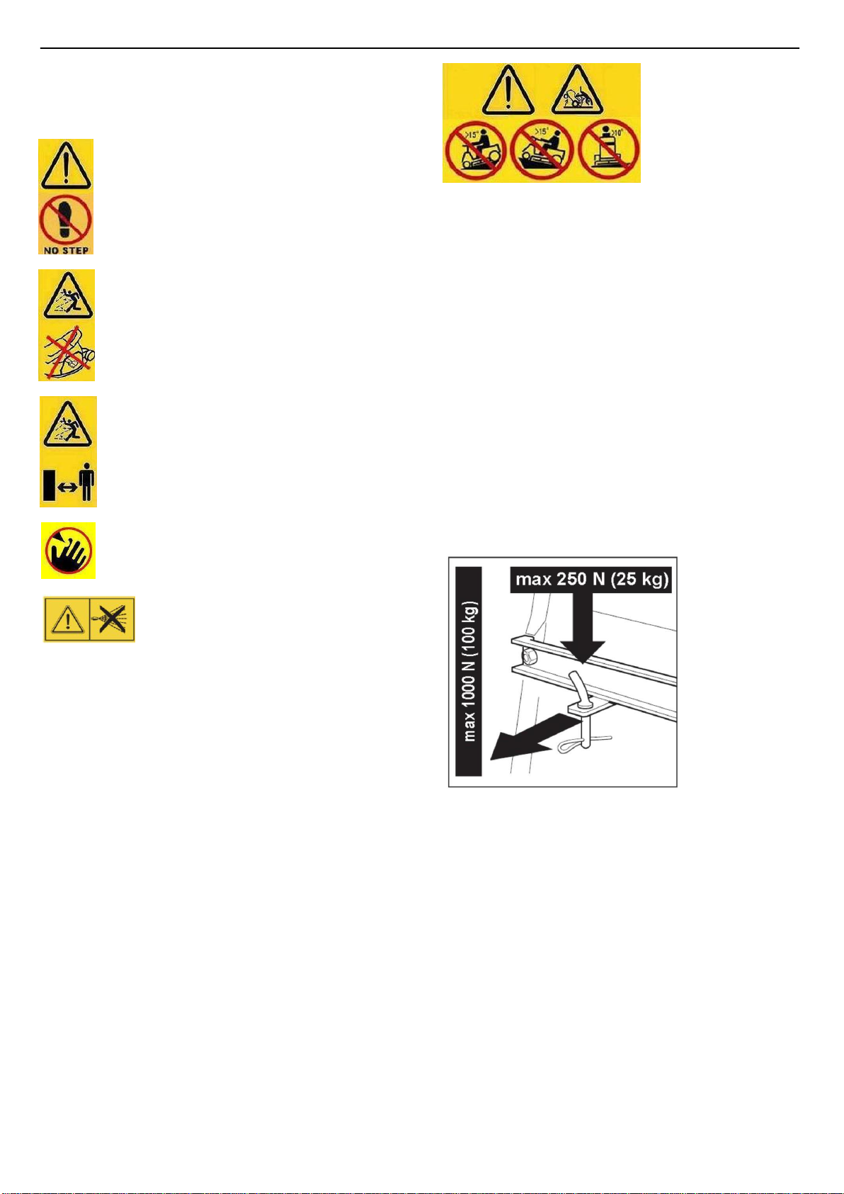
4) Do not use the machine on slopes with longitudinal gradients of more than 15°(27%). Do not use
the machine on slopes with lateral gradients above 10°(18%).
5) Remember there is no such thing as a “safe” slope. Travelling on grass slopes requires
particular care.
To guard against overturning:
–do not stop or start suddenly when going up or downhill;
–engage the drive slowly and always keep the machine in gear, especially when travelling downhill;
–machine speeds should be kept low on slopes and during tight turns;
–stay alert for humps and hollows and other hidden hazards;
–never mow across the face of the slope.
–use care when pulling loads or using heavy equipment:
–use only approved drawbar hitch points;
–limit loads to those you can safely control;
–do not turn sharply. Use care when reversing;
–use counterweight(s) or wheel weights whenever advised in the instructions manual.
6) Stop the blades before crossing surfaces other than grass.
7) Never use the machine with damaged guards, or without the safety protective devices in place.
8) Do not change the engine governor settings or overspeed the engine. Operating the engine at excessive
speed can increase the risk of personal injury.
9) Before leaving the driving seat:
-disengage the blades and lower the attachments;

7
–go into neutral and apply the parking brake;
–stop the engine and remove the ignition key.
10) Disengage the blades, stop the engine and remove the ignition key:
–before clearing blockages or unclogging the collector channel;
–before cleaning, checking or servicing the machine;
–after striking a foreign object. Inspect the machine for damage and make repairs before restarting and operating
the machine;
–If the machine starts to vibrate abnormally (check for the causes immediately).
11) Disengage the blades for transport or whenever they are not in use.
12) Stop the engine and disengage the blades:
–before refueling;
–before making height adjustments unless adjustment can be made from the operator’s position.
13) Reduce the throttle during engine run-out. If the engine is provided with a shut-off
14) Cut off the fuel with the fuel valve when you have finished mowing.
15) Watch out for traffic when crossing or near roadways.
16) Never direct discharge of material towards bystanders nor allow anyone near the machine while in
operation.
D) MAINTENANCE AND STORAGE
1) Keep all nuts, bolts and screws tight to be sure the equipment is in safe working condition.
2) Never store the equipment with petrol in the tank inside a building where fumes may reach an open flame or
spark.
3) Allow the engine to cool before storing in any enclosure.
4) To reduce fire hazards, keep the engine, silencer, battery compartment and petrol storage area free of
grass, leaves, or excessive grease.
5) Check the grass-catcher frequently for wear or deterioration.
6) Replace worn or damaged parts for safety purposes.
7) If the fuel tank has to be drained, this should be done outdoors.
8) On multi-bladed machines, remember that the rotation of one blade can cause other blades to rotate.
9) When the machine is to be parked, stored or left unattended, lower the cutting means unless a positive
mechanical lock is used.
1.3 SAFETY LABELS
Your machine must be used with care. This is why labels with illustrations have been placed on the machine, to
remind you of the main precautions to take during use. These labels are to be considered an integral part of the
machine. Should a label come off or become illegible, contact your dealer to replace it. Their meaning is
explained below.
Warning:
Read the instructions before
operating this machine.
Warning:
Disconnect the ignition key and read the
instructions before carrying out any repair
or maintenance work.
Danger!
Dismemberment:
Make sure that children stay clear of the
machine at all time when engine is running.
Danger!
Risk of burns
Wait for the engine to completelycooldown
before making any adjustments or servicing the
engine itself.
Warning:

8
No step on the deck or discharge guard.
Warning: Do Not Step
Danger: Ejected Objects
Always operate with the grass catcher or
discharge guard in place
Danger: Risk of Injury
Keep bystanders away
Blades continue to rotate after switching
off the engine or disengaging the blade.
Warning: Keep hands and feet away
from blades
Warning:
Never use a pressure washer on the
transmission system.
Danger: Risk of overturning on steep slopes
Do not use the machine on slopes with a longitudinal
gradient greater than 15 degrees (27%).
Do not use the garden tractor on slopes with a lateral
gradient greater than 10 degrees (18%).
1.4 CAUTION WHEN TOWING
A kit for towing a small trailer is available on request,
This accessory is to be fitted following the instructions
provided,When using the towing kit. Do not exceed the
recommended loads stated on the label and follow the
safety instruction.

9
2.
IDENTIFICATION
OF
THE
MACHINE
AND
COMPONENTS
2.1 IDENTIFICATION OF THE MACHINE
The label located in the seat bracket has the essential data of each machine
1. Name and address of manufacturer.
2. Designation of the machine
3. Type of machine
4. Cutting width
5. Mass of machine
6. Nominal power of engine
7. Serial number
8. Year of manufacture
9. Acoustic power level according to directive 2000/14/CE
10. Conformity mark according to directive 2006/42/EC

10
2.2IDENTIFICATION OF MAIN COMPONENTS
The main components of the machine as following:

11
3. UNPACKING AND ASSEMBLY
For storage and transport purposes, some components of the machine are not installed in the factory and have to
be assembled after unpacking.
Follow the instructions below:
The machine is supplied without engine oil or fuel. Before starting the engine, fill with oil and fuel
following the instructions given in the engine manual.
3.1 UNPACKING
When unpacking the machine, take care to gather all individual parts and fittings, and do not damage the cutting
deck when taking the machine off the pallet.
1.Machine body
2.Steering connect shaft
3.Towing kit
4.Bumper
5.Bumper bracket L
6.Bumper bracket R
7.Steering wheel cover
8. Steering wheel
9. Splined hub
10.Steering shaft cover
11.Instruction manual
12.Nuts, bolts,
washer,bushing and
starter key
13.Tools
14.Seat
15.Side deflector
16.Mulchig kit (if
applicable)
Raise the deck to its
maximum height when
taking the machine off
the pallet.

12
3.2FITTING THE STEERING WHEEL
Only for LT108MSL (TTM108S) Manual Transmission
Put the machine on a flat surface and straighten up the
front wheels.
a. Fit the shaft (1) onto the couplings and tightening the
screw M8x25 (2).
(Use the hex wrench 5 in accessories tools.)
b. Fit the steering shaft cover (3).
C. Fit the steering wheel 4 onto the steering shaft ,
insert screw (5) and tighten it by nut (6).
Put the machine on a flat surface and straighten up
the front wheels.
a.Fit the shaft (1) onto the couplings and tightening the
screw M8x25 (2). (Use the hex wrench 5 in accessories
tools.)
b.Fit the steering shaft cover (3).
c.Inset the splined hub (4) to shaft (1), mounting
steering wheel (5), spacer (6) and tightening nut M8
(7).(Use the open end wrench 13-15 in accessories
tools.)
d.Inset the steering wheel cover (8) into steering wheel
and tightening two screws (9). (Use the cross
screwdriver in the accessories tools.)
NOTE
Pay attention to the direction when mounting the
steering wheel .

13
3.3 FITTING THE SEAT
Mount the seat on the plate using the screws.(Use the open
end wrench 8-10 in accessories tools.
For optional seat only (if applicable):
a.
Fix the right armrest (1) on the seat with three M8 screws
(2) using the Allen wrench in accessories tools, and fix
the left armrest (3) on the seat in the same way;
b.
Snap the retaining ring (1) into the pin (2), use the pin to
link the seat (3) to the bracket, and snap it into the
retaining ring (4).

14
3.4 CONNECTING THE BATTERY
The electrolytic fluid is a solution of sulphuric acid.
Danger: Sulphuric acid is poisonous
Danger: Sulphuric acid is corrosive Sulphuric acid can cause blindness or severe burns.
Danger: Keep out of reach of children.
For EU countries only
Never place any electric power tools in your household refuse.
To comply with European Directive 2012/19/EC concerning old electric and electronic equipment and its
implementation in national laws, old electric power tools have to be separated from other waste and disposed of
in an environment-friendly fashion, e.g. by taking to a recycling depot.
Fit the battery in its housing.
IMPORTANT
Position the battery with the polarities(+)and(—)
Connect the battery connectors to the machine connection leads
and tighten the 2 screws. then cover the protective cap for the 2
wire is in place. (Use the open end wrench 8-10 and cross
screwdriver in accessories tools)
1)
Secure the battery with the small rubber strap.
The battery type:
12 V 18Ah.
The battery is fully charged before leaving the factory.
If the battery is found to be insufficient, please use a 12V1A
charger to charge the battery.
3.5MOUNTING THE FRONT BUMPER
Mounting the bumper bracket L and bumper bracket R on the
bumper, using 4 nuts and 4 screws. (Use the open end wrench
13-15 in accessories tools.)
Mounting the front bumper on the bottom of the frame using the
4 nuts and 4 screws. (Use the open end wrench 13-15 in
accessories tools.)

15
3.6 MOUNTING THE SIDE DEFLECTOR
a.Insert the plastic pin (1) and washer (2) into the right end of the
pin (3);
b.Insert the pin shaft into the side deflector (4), bracket (6) and
torsion spring (5) in sequence, and insert the washer (2) and
elastic latch (1) at the other end.
Note: When you need to open the side deflector, please
press the self-locking button first, and do not force it to open.
3.7 MOUNTING THE MULCHING KIT (optional)
Mulching grass reduces grass cuttings by cutting the grass
clippings more than once. Grass should be dry and only a third of
the length should be cut for best results. If the grass is very long,
set the height of cut higher and then re-mow at a lower cut.
A mulching kit is required to convert side discharging tractors to
mulching. The instructions below describe the fitting of the kit:
a. Press the self-locking button to open the side deflector;
b. Pass the lug boss (M) on the mulching kit through the bottom
of the pin (N), insert the lower left corner of the mulching kit into
the space under the self-locking parts base (Figure B), and insert
the right dowel pin into the hole of deck (Figure C);
c. Hang the left hook into the groove on the base of the self-
locking parts (Figure A), and the right hook into the hole of the
deck (Figure D).

16
3.8
MOUNTING THE TOWING KIT
a.Remove the tension arm bushing (2), the hexagonal flange
bolts M8×20 (3), and the hexagonal flange locking nuts M8 (1)
that secured the gearbox cover (4);
b.Insert the bushing (2) into the two holes where the bolts were
just removed, align the towing plate (5),
Then install the hexagonal flange bolts M8×40 (3), hexagonal
flange locking nut M8 (1), and then tighten the bolt.

17
4.CONTROLS AND INSTRUMENTS
4.1THROTTLE LEVER
This regulates the engine revs. The positions are indicated on a label showing the following symbols:
«CHOKE» cold starting
«SLOW» for minimum engine speed
«FAST» for maximum engine speed

18
–The «CHOKE» position enriches the mixture so must only be used if necessary when starting from cold.
–When moving from one area to another, put the lever in a position between «SLOW» and «FAST».
–When cutting, shift into «FAST»
4.2STEERING WHEEL
Turns the front wheels
4.3BLADE START/STOP KNOB
The blade start/stop knob is located on the RH console in front of the key switch.
The blade start/stop knob operates the electric clutch. Pull the knob upward to
engage the blades, or push the knob downward to disengage the blades.
4.4 KEY IGNITION SWITCH
This key operated control has four positions:
«OFF» everything is switched off.
«ON» activates all parts
«START» connects the starter Motor.
If you release the key on «START», it will automatically return to «ON».
This selection sends power to the head lights when the switch is in this position.
4.5 Brake Pedal
The brake pedal is located on the left front side of the board. The brake pedal can be
used for sudden stops or setting the parking brake.
When the machine is moving, keep your foot off the pedal.
4.6 PARKING BRAKE LEVER
With themachine stopped
:
1)
Keep the brake pedal pressed
;
2)
Lift the parking brake lever and keep lifted
;
3)
Release the brake pedal.
This way, the rear wheelsremain braked. To release
the parking brake, fully press the brake pedal (the
parking brake lever is automatically released and returns to down position).
The engine can only be started at the parking position.

19
4.7DRIVE ENGAGEMENT PADAL
(for hydrostatic transmission model)
This pedal engages drive in the wheels as well as modulating
the machine’s forward and reverse speeds.
To engage forward drive, press
it towards «F» with your toecap.
As you increase the pressure on the pedal, the
speed of the machine increases.
Reverse is engaged by pressing the pedal with the heel
towards «R».
The pedal automatically goes into neutral «N» when released.
Reverse must only be engaged when the machine is stopped.
Release the parking brake whilst engaging the drive
4.8SPEED CHANGE LEVER
(for manual gear model)
This lever has seven positions for the 5 forward speeds,
the neutral position «N», and reverse «R».
When shifting the speed change lever, press the brake pedal to
disengage the drive belt and shift the lever as shown on the label.
Never directly shift the lever from forward to reverse or from
reverse to forward before the machine coming to stop completely.
Only shift into reverse when the machine has stopped moving.
4.9CUTTING HEIGHT ADJUSTMENT LEVER
Lifts or lowers the blade deck and thereby adjusts the grass cutting height. There are seven positions
for this lever (shown as «1» to «7» on the label), which correspond to various heights between 30 and
90 mm
4.10 SEE DESCRIPTION IN 5.3.3
4.11 Reverse Mode Operation Button (RMO)
The reverse mode operation knob is located on the RH console to the left of the blade start/stop knob. The blades
will stop when traveling in reverse. To keep the blades rotating when traveling in reverse, press the button RMO.
NOTE: Mowing in reverse is not recommended. Always ensure it is safe to mow before proceeding.

20
5 HOW TO USE THE MACHINE
5.1 SAFETY RECOMMENDATIONS
The machine must only be used for the purpose for which it was designed (cutting grass). Do not tamper with or
remove the safety devices fitted on the machine.
REMEMBER THAT THE USER IS ALWAYS RESPONSIBLE FOR DAMAGE AND INJURY TO OTHERS.
Before using the machine:
–read the general safety regulations, paying particular attention to driving and cutting on slopes;
–carefully read the instructions for use, make sure you are familiar with the controls and know how to stop the blades
and the engine quickly;
–never put your hands or feet next to or beneath the rotating parts and always keep away from the exit.
Do not use the machine when unwell or under the influence of medicine or any other substances that can reduce
your reflex actions and your ability to concentrate. It is the user's responsibility to assess the potential risk of the
area where work is to be carried out, and to take all the necessary precautions to ensure their own safety and that
of others, particularly on slopes or rough, slippery and unstable ground.
Do not leave the machine on high grass with the engine running to avoid the risk of starting a fire. Ensure grass
cuttings are cleared from the tractor to avoid a potential fire.
Do not use the machine on slopes with longitudinal gradients of more than 15°(27%); do not use
the machine on slopes with lateral gradients above 10°(18%). If the machine is likely to be used
mostly on sloping ground fit counterweights beneath the cross-member of the front wheels. These
improve stability at the front and reduce the chances of tipping over.
All the references relating to the positions of controls are described in chapter 4.
5.2THE SAFETY DEVICES OPERATION
The safety devices work in two ways:
–they prevent the engine from starting if all the safety requirements have not been met;
–they stop the engine even if just one of the safety requirements is not met.
a) To start the engine, it is necessary that:
–the blades are not engaged
;
–the parking brake is engaged and the transmission is disengaged
;
–the operator sits on the seat;
b) The engine stops when:
- the operator leaves his seat while mowing or driving;
5.3DIRECTIONS BEFORE STARTING WORK
Before starting to mow, it is necessary to carry out several checks and operations to ensure
you can work efficiently and in maximum safety.
5.3.1 Seat adjustment
To change the seat position, loosen the four fixing bolts and slide it along the slots.
Once you have found the right position, tighten the four screws.
Where the optional seat is fitted
To adjust the position of the seat, pull up and hold the seat adjustment lever. Slide the seat
forward or rearward to the desired position; then release the adjustment lever. Make sure
seat is locked into position before operating the tractor.
This manual suits for next models
3
Table of contents
Other Cobra Tractor manuals