Cobra GTT400HD User manual

Cart shown above may differ slightly in design from actual cart.
MODEL: GTT400HD
HEAVY DUTY DUMP TRAILER
OWNERS MANUAL

COBRA CARTS AND TRAILERS - INSTRUCTION MANUAL
2
YOU MUST READ THIS DOCUMENT BEFORE YOU
BEGIN TO ASSEMBLE THE POLY DUMP CART.
Thank you for purchasing this poly dump cart. When
properly assembled and maintained, this product will
provide years of reliable service. These instructions include
helpful hints and important information needed to safely
assemble and properly maintain the dump cart. Please
read these instructions before you begin.
If you have any questions during the assembly, contact
Customer Service for assistance.
SAFETY PRECAUTIONS
Do not use the dump cart if any part is broken or
damaged.
This dump cart is not a toy . Do not allow children use
the dump cart.
Do not use on inclines; dump cart may tip or roll away.
Do not load your dump cart with more than 600lbs.
Inflate the tires with ambient air only.
Inflate the tires to the proper level as indicated on the
tires. Do not inflate tires more than 30 PSI.
Never use a flammable gas to inflate the tires.
Always set the handle to its standard position when
pulling the cart with a garden tractor.
Never allow riders in the dump cart.
Always empty the dump cart before disconnecting it
from a garden tractor.
Cart tongue must be in its retracted or standard
position when the cart is not pulled.
Stand clear of the tongue and handle when dumping
the dump cart; each will raise when the cart is dumped.
CARE AND MAINTENANCE
Periodically check nuts and bolts to make sure they are
tight and secure.
Clean the dump cart using water and mild soap. Rinse
with water sprayed from a garden hose. (Tip the dump
cart forward to let water drain out after washing.)
Inspect the cotter pins in the axle and verify that they
are in position and in good condition.
Check the tire pressure and adjust to recommended
pressure if needed.
Periodically lubricate the caster to ensure smooth
operation.
REQUIRED TOOLS
The following list identifies the main tools needed for
assembly. Recommended two (2) people for assembly.
Flathead and Phillips screwdriver
Metric and standard wrenches and socket set
Pliers
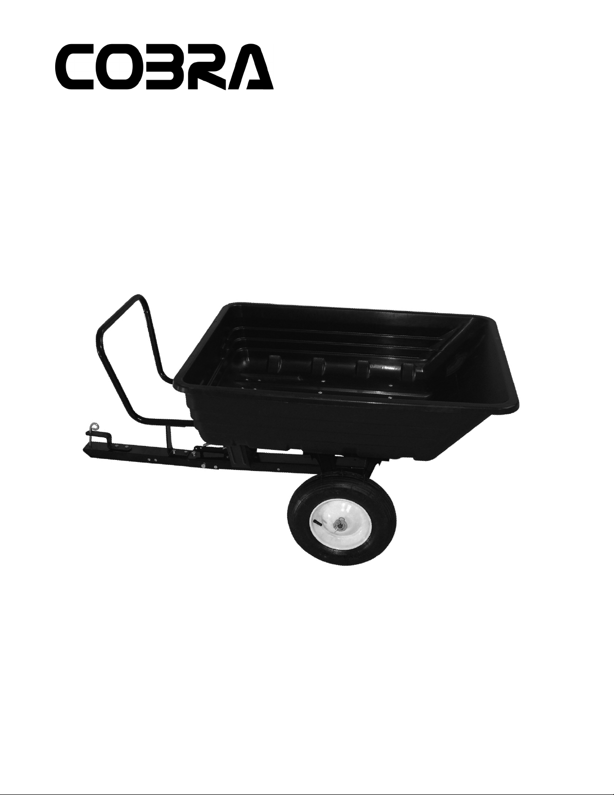
UNPACK AND IDENTIFY PARTS
The following steps will ensure that you have all the
necessary parts before you begin to assembly.
Unpack the contents of the shipment and place where 1.
you can easily inventory the parts.
If anything is missing or you have questions, consult 2.
the Pictorial Parts List or contact Customer Service.
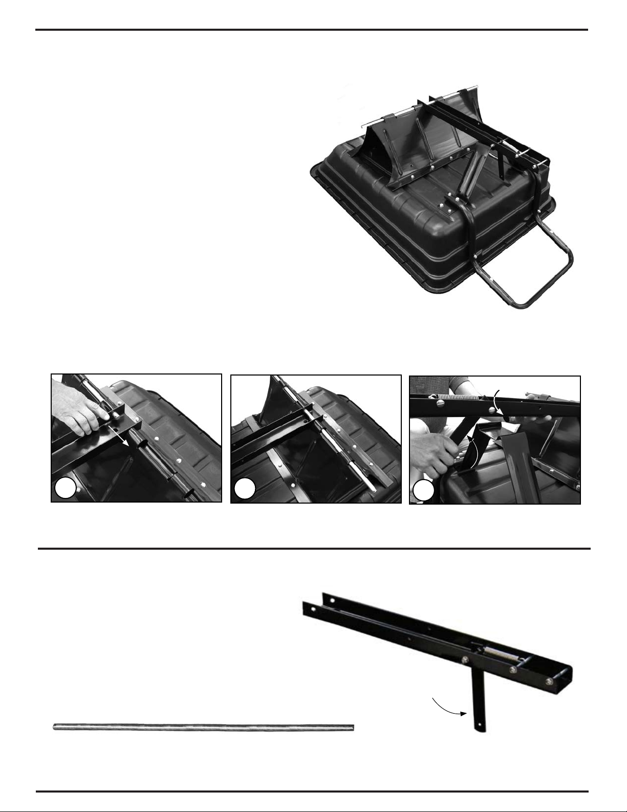
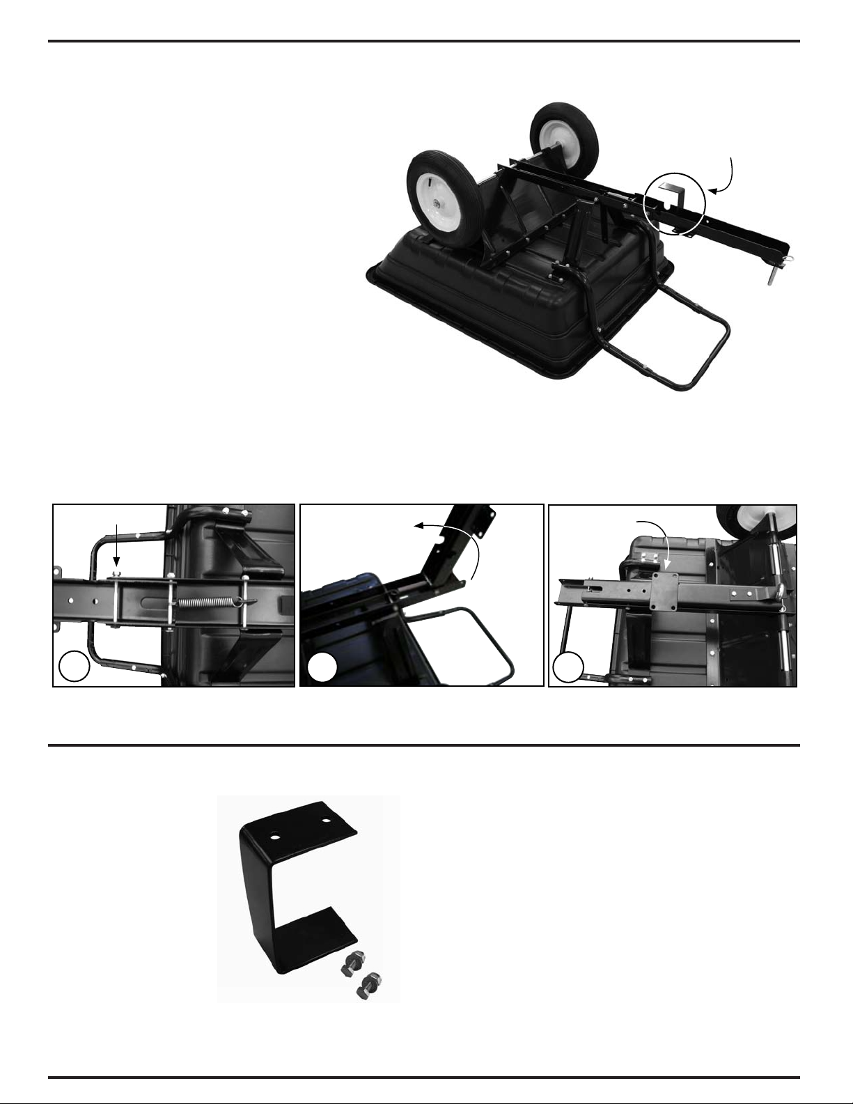
Pull cart with stand
Push cart with caster

3
CARTS AND TRAILERS
Parts List and Tools Required
M10 x 20mm Bolts (10) M10 Hex Nut (10)
M10 Lock Washer (10)
Axle Plate (1)
Tub (1)
Socket/Wrench Set
The following steps show how to assemble
the pull style dump cart.
NOTE: Fasteners needed to secure the axle
plate to the tub are attached to the axle plate.
Photo shows the axle removed from the axle
plate. Axle is shipped inserted into the axle
plate and can be removed during installation if
desired.
With assistance, place the tub on its side 1.
on a flat surface and hold or brace in
position.
NOTE: You must be able to access the
inside and underside of the tub to attach
the axle plate.
Align the holes of axle plate with the holes 2.
of the tub as shown in diagram A.
Secure the axle plate to the tub using the 3.
ten (10) M10x20 bolts, M10 flat washers,
M10 lock washers, and M10 nuts.
Insert all bolts through the dump cart tub
with the head of the bolts to the inside of
the tub. The nuts and lock washers are
to the outside against the axle plate as
shown in diagram B.
Tighten all bolts. 4.
1
ATTACH AXLE PLATE
AB
Phillips Screwdriver

4
NOTE: Fasteners needed to secure the support to
the tub are attached to the support.
Align the holes of the support with the holes 1.
near the end of the tub (A).
Secure support to the tub using four (4) M8x15 2.
bolts, four (4) M8 flat washers, four (4) M8 lock
washers, and four (4) M8 hex nuts.
NOTE: Secure bolts into the outer bolt holes.
See white arrows below (B). The inner bolt
holes are used to attach the handle assembly.
Insert all bolts through the dump cart tub with
the head of the bolts to the inside of the tub
Tighten all bolts.3.
ATTACH SUPPORT
Support
A
Support
M8 Lock Washer (4)
M8 Flat Washer (4) M8 Hex Nut (4) M8 x 15mm Bolts (4)
Socket/Wrench Set
Phillips Screwdriver
B
COBRA CARTS AND TRAILERS - INSTRUCTION MANUAL
Parts List and
Tools Required

CARTS AND TRAILERS
5
Parts List and
Tools Required
ATTACH HANDLE ASSEMBLY
Handle Assembly (1)
M8 Lock Washer (6) M8 Flat Washer (6)
M8 Hex Nut (6)
Flat Screwdriver
Socket/Wrench Set
M8x50 Bolts (6)
M8x50 Bolts
M8 Washers
M8 Nuts
A
M8x50 Bolts
M8 Washers
M8 Nuts
B
NOTE: Fasteners needed to secure the handle
assembly to the tub are attached to both the
support and handle assembly.
Insert all bolts through the dump cart tub with
the head of the bolts to the inside of the tub.
Align the holes of the handle assembly with 1.
the holes of the support.
Secure handle assembly and support to the 2.
tub using four (4) M8x50 bolts, four (4) M8
flat washers, four (4) M8 lock washers, and
four (4) M8 hex nuts. See diagram A.
Secure the handle to the edge of the tub 3.
using two (2) M8x50 bolts, two (2) M8 flat
washers, two (2) M8 lock washers, and two
(2) M8 hex nuts as shown in diagram B.
Tighten all bolts.4.

6
Parts List and Tools Required
If needed, remove the axle, washers, and cotter pins 1.
and set the axle and fasteners aside in a safe place.
Position the dump lever assembly, with the spring 2.
facing up, onto the support and into the center
space of the axle plate as shown in the photo to the
right.
Insert the axle through the axle plate and through 3.
the hole in the dump lever assembly as shown in
diagrams A and B.
Pull the dump lever, press the assembly against 4.
the support and slide the notch in the lever over the
support as shown in diagram C to secure the two
components.
ATTACH DUMP LEVER ASSEMBLY
Dump Lever
Lever Notch
ABC
Dump Lever Assembly (1)
Dump Lever
Axle (1)
COBRA CARTS AND TRAILERS - INSTRUCTION MANUAL

CARTS AND TRAILERS
7
Parts List and
Tools Required
Cotter Pins (2)
Pliers Wheels (2)
Wheel Washer (2)
ATTACH WHEELS
Slide a wheel onto the axle with the valve stem 1.
outward.
Using the washer and cotter pin that was set aside 2.
earlier in these instructions, slide the washer onto
the axle and insert a cotter pin through the hole in
the end of the axle.
Using pliers, spread the ends of the cotter pin to 3.
prevent it from falling out and to secure wheel.
Repeat the above steps to install the remaining 4.
wheel.

8
Parts List and
Tools Required
Tongue Support
Tongue
Assembly
Using diagram A for reference, remove the 1.
two outer 3-1/2" bolts from the dump lever
assembly.
NOTE: Unhook the spring from the dump
lever using a pliers to easily remove the
bolt if desired. See the circle in diagram A.
Position the tongue assembly, with the 2.
tongue support facing up as shown in the
diagram to the right, into the dump lever
assembly.
Align the bolt holes and secure in place 3.
using the same 3-1/2" bolts removed earlier
in Step 1. See diagrams B, C, and D.
NOTE: Reinstall the spring as shown
below. Verify that one end is hooked to the
dump lever and the other is secured by the
bolt. See diagram D.
ATTACH TONGUE ASSEMBLY
Flat Screwdriver
10M Socket Wrench
Tongue Assembly (1)
Tongue Support
Pliers
ABC D
COBRA CARTS AND TRAILERS - INSTRUCTION MANUAL

9
ATTACH TONGUE ASSEMBLY (continued)
With the tongue assembly secured to the 4.
dump lever assembly, carefully turn the
dump cart right onto its wheels.
NOTE: When pulling the cart with a garden
tractor, the handle must be in the standard
position. See white arrow in photo to the
right.
This position helps prevent the handle from
contacting the garden tractor when in use.
Return to all fasteners and verify that they 5.
are tight.
DUMPING THE CART
To dump the cart when it is attached to a garden tractor,
pull the dump lever forward as shown in the diagram to the
right.
WARNING: To prevent damage and possible injury,
never disconnect a loaded cart from the garden tractor.
The cart must remain attached to a garden tractor
until it is emptied.
Stay clear of the handle as the tub tilts.
CARTS AND TRAILERS

10
PUSH CART ASSEMBLY
To convert the pull cart to a push cart follow
these instructions:
After assembling the dump cart, remove the 1.
tongue support, and store the support and
fasteners in a safe place for future use.
Remove the outer 3-1/2" bolt (A) from the 2.
tongue assembly. See black arrow.
Pivot the tongue back toward the axle (B). 3.
The tongue rests inside the dump lever
assembly as shown in diagram C.
Remove tongue support.
Tongue brace and hardware
ABC
Caster Plate
COBRA CARTS AND TRAILERS - INSTRUCTION MANUAL
Parts List

CARTS AND TRAILERS
11
Parts List and
Tools Required
PUSH CART ASSEMBLY (continued)
Secure caster to the caster mounting 4.
plate using four (4) M12 bolts, four (4)
washers, and four (4) nuts, which were
attached to the caster during shipping.
See diagrams A and B.
Reattach the 3-1/2" bolt, washer and 5.
nut (removed earlier) to lock the tongue
assembly in place. Consult diagrams C
and D.
Tighten all bolts.6.
10M Socket Wrench Caster (1)
Flat Washer (4) Hex Nut (4)
Bolts (4)
Flat Screwdriver
ABC D

12
Carefully flip the dump cart onto its wheels.7.
Adjust the handle as desired using the handle 8.
bolts and either of two (2) holes. Handle is
shipped in the standard position.
Extended Handle Position: Remove the
bolts and extend the handle. Align the bolt
holes and secure the handle using bolts,
washers, and nuts.
Return to all fasteners and verify that they 9.
are tight.
Standard Handle Position Extended Handle Position
Dump cart shown with the handles in the extended position.
PUSH CART ASSEMBLY (continued)
COBRA CARTS AND TRAILERS - INSTRUCTION MANUAL

13
Parts List and Tools Required
DUMPING THE CART
To dump the cart when it is pushed by hand, raise the handle and tip the cart forward until the front or slanted edge of
the tub rests on the ground.
To dump the cart when it is attached to a garden tractor, pull the dump lever forward as shown in the diagram below.
WARNING: To prevent damage and possible injury, never disconnect a loaded cart from the garden tractor. The
cart must remain attached to a garden tractor until it is emptied. Stay clear of the handle when dumping the cart!
Dump cart shown with the handle in the standard position.
NOTE: Convert the push cart to a pull cart by
removing the anchor bolt (see diagrams below)
on the tongue assembly, swing the tongue as
shown to the right to its extended position, and
secure in place using the anchor bolt.
When pulling the cart with a garden tractor, set
the handle in the standard position as shown in
the diagram to the right. (See previous page.)
This position helps prevent the handle from
contacting the garden tractor when in use.
PUSH CART ASSEMBLY (continued)
Move anchor bolt to this
position to secure tongue.
Pivot Bolt
Pivot Bolt
Anchor
Bolt
COBRA CARTS AND TRAILERS - INSTRUCTION MANUAL
Table of contents
Other Cobra Utility Vehicle manuals
Popular Utility Vehicle manuals by other brands

forest river
forest river WIDE BODY Series operating manual

Carry-On Trailer Corporation
Carry-On Trailer Corporation 7x16CG User's manual - safety guide

Club Car
Club Car CARRYALL 294 Owner's manual supplement

Kendon
Kendon Stand-Up SINGLE RIDE-UP Go Series instructions

Dazon
Dazon Raider Max 175S owner's manual

Cub Cadet
Cub Cadet MX 550 Operator's manual