COEF MP250 FRESNEL User manual

Printed in January 1999
MP250 FRESNEL
COEF srl.
Via Albinatico, 80-82
51019 Ponte Buggianese (PT)
ITALY
•MANUALE ISTRUZIONI
•OPERATING INSTRUCTION

Pag. 2 COEF srl. Ponte Buggianese (Pistoia) ITALY
®
COEF srl.
Via Albinatico, 80-82 Ponte Buggianese 51019 ( Pistoia ) ITALY
tel. (+39) 0572-636536 r.a. Fax (+39) 0572 - 636535
Tutti i diritti di riproduzione, diffusione del presente manuale sono riser-
vati a COEF srl.
Le descrizioni ed illustrazioni fornite nella presente pubblicazione non
sono impegnative.
COEF srl. si riserva il diritto di apportare in qualsiasi momento tutte le
modifiche che riterrà opportune.
Il presentemanuale non può essere ceduto in visione a terzi senza spe-
cifica autorizzazione scritta dalla COEF srl.
All rights for reproduction of this catalogue are reserved for COEF srl.
Descriptions and illustrations are not binding.
COEF srl. reserves the right to make all necessary modifications at any
time. This manual can not be inspected by third party, without written autori-
zation by COEF srl.
Les droits de reproductionde ce catalogue sont entiérementréservés à
la Société COEF srl.
Les descriptions et les illustrations fournies dans ce manuel nengagent
acunement notre Société.
COEF srl. se réserve le droit dapporter, à tout moment, les modifica-
tions quelle jugera utiles.
Ce manuel ne peut être remis à des tiers sans lautorisationpréalablede
la Société COEF srl.
Alle Rechte vorbehalten. Nachdruck verboten.
Die in diesem HandbuchenthaltenenBeschreibungenund Abbildungen
sind nicht verbindilich.
Die Firma COEF srl. behält sich das Recht auf Änderungen zu jedem
Zeitpunkt vor.
Diese Bedienungsanleitungdarf ohne schriftlicheGenehmigungder Fir-
ma COEF srl. dritten Personen nicht zugänglich gemacht werden.

COEF srl. Ponte Buggianese (Pistoia) ITALY Pag. 3
Questo manuale è organizzato in modo tale che lutente, linstallatore o il manutentore dellapparecchiatura descritta, venga
supportato da quelle informazioni indispensabili per un uso corretto delle procedure di installazione e di funzionamento dellappa-
recchiatura stessa. Le varie procedure verranno appositamente segnalate (dove sarà necessario) da segnali indicatori che evi-
denzieranno sia le pericolosità delloperazione che le necessità di un intervento tecnico. Di seguito vengono rappresentati questi
OPERATORE / OPERATOR
Personale non espressamente qualificato in grado di eseguire operazioni dove non è richiesta
una conoscenza specifica.
Not particulary qualified staff, that can operate when no specific knowledge is required.
This manual has been organized in order support the user, the installer or the maintenance operator of the de-
scribed unit with those necessary informations for a correct use of the installation and working procedures of the
same unit. The various procedures will be just signalled by indicators (when necessary) evidencing the operation
dangers and the necessity of technical support. Please find here below a list of symbols and relative meaning:
OPERATORE COEF
/
COEF OPERATOR
Personale tecnico qualificato e responsabilizzato dal costruttore, per tutte le operazioni di ripa-
razione o interventi straordinari.
Technicalstaff, qualifiedand trainedby the constructor,for repair and extraordinaryoperations.
MANUTENTORI MECCANICI
/
MECHANICAL OPERATORS
Personale addetto alla manutenzione ordinaria di natura meccanica.
Staff employed in the ordinary mechanical maintenance.
MANUTENTORI ELETTRICI
/
ELECTRIC OPERATORS
Personale addetto alla manutenzione ordinaria di natura elettrica.
Staff employed in the ordinary electric maintenance.
SEGNALE DI PERICOLO
/
DANGER SIGNAL
Segnalazione di parti sotto tensione.
Electric shock danger signal.
OPERATORI MECCANICI SPECIALIZZATI
/
SPECIALIZED MECHANICAL OPERATOR
Personale qualificato addetto alla installazione o alle riparazioni straordinarie autorizzate.
Qualified staff employed in extraordinary authorized installations and repairs.
OPERATORI ELETTRICI SPECIALIZZATI
/
SPECIALIZED ELECTRIC OPERATORS
Personale qualificato addetto alla installazione o alle riparazioni straordinarie autorizzate.
Qualified staff employed in extraordinary authorized installations and repairs.
SEGNALE DI PERICOLO
/
DANGER SIGNAL
Segnalazione di pericolo generico.
Generic danger signal.
1.0 Come usare il manuale - How to use the manual

Pag. 4 COEF srl. Ponte Buggianese (Pistoia) ITALY
2.0 INSTALLAZIONE - INSTALLATION
Il Fabbricante si ritiene sollevato da eventuali responsabilità in caso di:
•
uso improprio della apparecchiatura o da parte di personale non addestrato
•
uso contrario alla direttive in materia di sicurezza sul lavoro
•
installazione non corretta
•
difetti di alimentazione
•
gravi carenze nella manutenzione prevista
•
modifiche o interventi non autorizzati
•
utilizzo di ricambi non originali o non specifici per il modello
•
inosservanza totale o parziale delle istruzioni
•
eventi eccezionali
La lampada deve essere sostituita se è stata danneggiata o deformata dal calore
ATTENZIONE: disconnettere l’alimentazione al proiettore prima dell’operazione.
Leggere attentamente le istruzioni d’uso fornite dal costruttore della lampada.
The lamp must be changed if damaged or deformed by heat.
WARNING: switch off the projector before operating.
Read carefully the lamp builder’s instructions.
The constructor is not to be considered responsible in the case of:
•
improper use of the unit or use by not trained staff
•
use in contrast with the directions on work safety
•
wrong installation
•
defective power supply
•
serious lacks in the necessary maintenance
•
unauthorized modifications and interventions
•
use of spare parts that are not original or not specific for the unit
•
total or partial inobservance of instructions
•
Unusual events
2.1 Montaggio o sostituzione lampada - Lamp mounting and replacing

COEF srl. Ponte Buggianese (Pistoia) ITALY Pag. 5
E
Lapparecchio monta una lampada ad alta pressione con accenditore tradizionale esterno.
La regolazionedella lampada è indispensabileper ottenere un fascio luminoso uniformee potente. Accendereil
proiettore ed impostare il canale otturatore aperto e quello del colore su bianco.
Regolarele 3 viti a croce(part. B) finoa raggiungerela condizioneideale tra potenzadelfascio ed omogeneità.
ATTENZIONE!
La lampada è pre-regolata in fabbrica. Regolare solo finemente. Non portare le viti al punto
estremo inferiore o superiore della loro corsa.
Prima di intervenire, attendere almeno 10 minuti dopo lo spegnimento per consentire il raffreddamento
parziale e prevenire la possibilità di esplosione della lampada. Attendere globalmente 20 minuti, se si opera
a mani nude, per evitare scottature.
Rimuoverele due viti a croce (part.A) che fissano il coper-
chio del portalampada. Inserire la lampada nello zoccolo con
cautela, evitando il contatto della lampada con la pelle delle
mani. Inserire quindi la lampadamontata nel corpo del proiet-
tore con molta cura facendo attenzione che il cavo di collega-
mento ritorni nella sua posizione naturale.
Riavvitare le due viti per fissare di nuovo il coperchio della
lampada al proiettore.
Wait at least 10 minutes after the projector has been
switched off before operating again, in order to let it cool
down and avoid the lamp explosion. Wait 20 minutes in
case you are operating with bare hands in order to avoid
burns.
Screw the two screws off (part.A) and remove the round
cover thats supporting the lampholder. Insert the lamp
(MSD250/2) in the socket. Insert delicately the lamp inthe projector support, driving it with the round cover.
Pay attention:the lampholders wires must correctlyreenterin the projector.Block the cover screwingthe screws
up.
2.2 Regolazione Lampada - Lamp adjustment
Lamp adjstment is necessary to obtain a uniform and powerful light beam. Switch on the projector and set the
shutter to open, set the color as white. Adjust the three screws (part. A) until you reach the ideal condition between
power and homogeneity.
WARNING! The lamp is pre-regulatedby the factory. Only fine-adjustmentis required. Dont move the screws A
up to upper or lower extremities.

Pag. 6 COEF srl. Ponte Buggianese (Pistoia) ITALY
2.3 Montaggio dell’apparecchiatura - Machine Installation
Per il fissaggio dell
MP250 FRESNEL
è indispensabile, quando linstallazione
è prevista su di una attrezzaturadI sostegno sollevata da terra, bloccare le staffe di fissaggio in dota-
zione allapparecchio con una adeguata vite con dado e controdado di misura non inferiore a
M10X50
, da inserire nel foro centrale predisposto sulle staffe di fissaggio.
Per garantire una sicurezza essenziale e nel rispetto delle attuali norme di sicurezza per linstallazione delle ap-
parecchiature,è obbligatorioinstallare una catena di sicurezza(o cavo dacciaio)con moschettoniche collegail cor-
po macchina dell
MP250FRESNEL
alla struttura di ancoraggio.
Importante:
la fune di sicurezza dovrà essere installata e montata a regola darte alla struttura di sostegno, in
modo che, in caso di cedimentodella staffa di fissaggio principale, si realizzi la minor caduta possibile dellapparec-
chiatura.
Dopo tale intervento, la fune di sicurezza deve essere sostituita con il ricambio originale.
ATTENZIONE: COEF non risponde di installazioni scorrette od effettuate senza il rispetto delle suddette indica-
zioni, e quindi considerate pericolose.
To fix the
MP250 FRESNEL
is necessary, when the installation has to be on a
raised-from-the ground support, to block the fixing bracket of the unit by means of a screw provided
with nut and locknut measuring not less than
M10X50
, to insert in the central pre-arranged hole on
the fixing bracket.
In order to guarantee a necessarysecurity andin respect of the actualsafety rulesconcerning the projectors in-
stallation,it is compulsory to install a safety-chain (or steel cable),equipped with spring clips, to connectthe
MP250
FRESNEL
body to the fixing structure.
ATTENTION:
the safety-chain must be properly installed and fixed to the supporting structure, in a way that an
incidental givin in of the main bracket would leed to the shortest possible fall of the projector.
After such an inter-
vention the safety-chain must be replaced with an original spare part.
ATTENTION:COEF is not responsiblefor installations not correctly made or made without respecting the abo-
ve indications: those installations are considered dangerous..

COEF srl. Ponte Buggianese (Pistoia) ITALY Pag. 7
2.4 Una corretta installazione - Advices for a correct installation
Per un corretto funzionamento dellapparecchiatura rispettare le seguenti condizioni:
1) Non installare il proiettore allesterno dove è possibile linfluenza di agenti atmosferici dannosi al funziona-
mento dellapparecchiatura stessa (pioggia, vento, sole intenso ecc. ).
2) Non eseguire la pulizia del proiettore con getti di acqua o immersionein altri liquidi, ma attenersi scrupolo-
samente a quanto indicato nel capitolo MANUTENZIONE.
3) Eseguire i collegamentielettrici e la installazione/ sostituzionedella lampadain assenza di tensionedi ali-
mentazione e con linterruttore di accensione in posizione OFF.
4) Non manomettere in alcun modo le parti interne ed esterne del proiettore senza preventiva autorizzazione
del fabbricante e senza che le modifiche vengano eseguite da personale qualificato.
5) Assicurarsi del corretto fissagio del proiettore alla struttura di sostegno come indicato al paragrafo 2.3.
6)
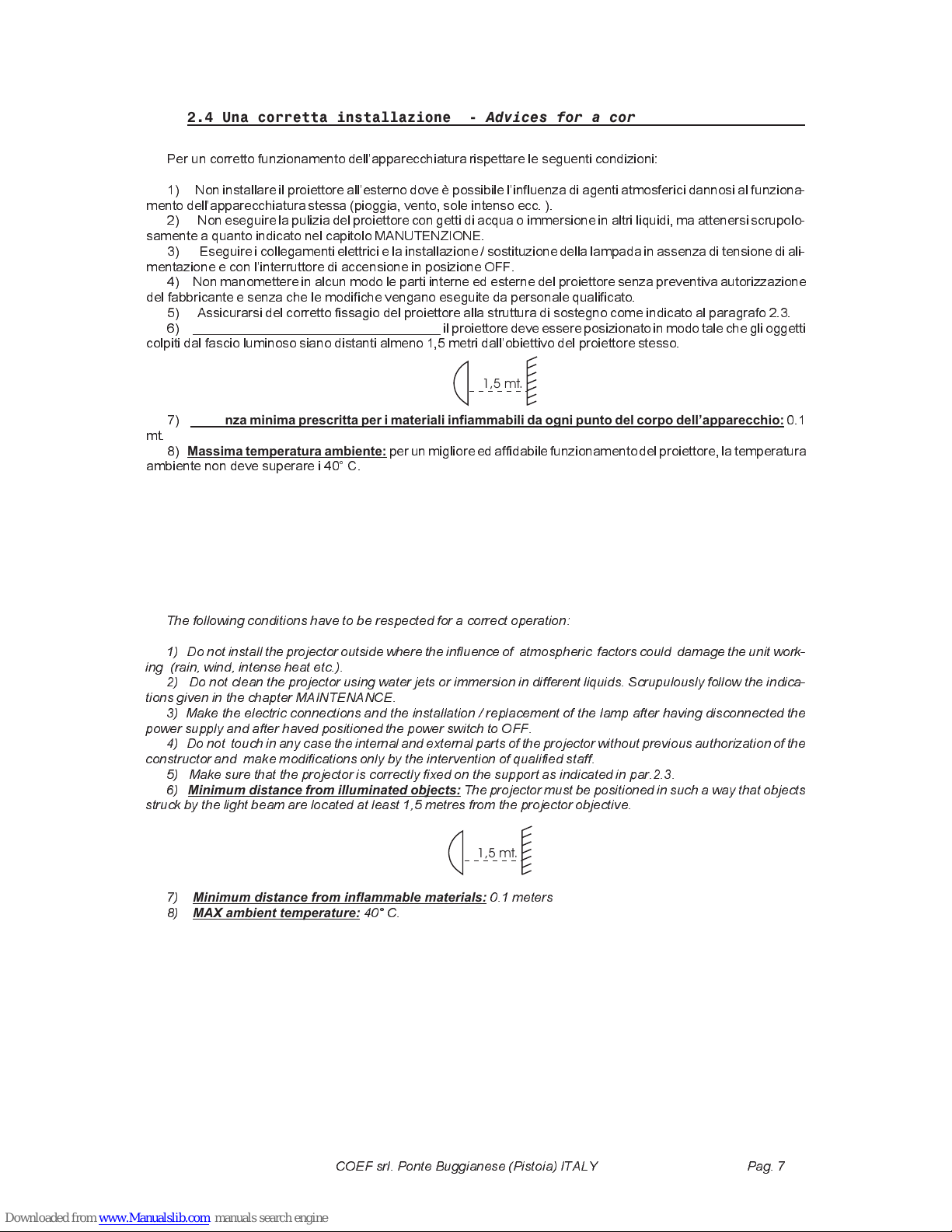
Distanza minima degli oggetti illuminati:
il proiettore deve essereposizionatoin modo tale che gli oggetti
colpiti dal fascio luminoso siano distanti almeno 1,5 metri dallobiettivo del proiettore stesso.
7)
Distanza minima prescritta per i materiali infiammabili da ogni punto del corpo dell’apparecchio:
0.1
mt. 8)
Massima temperatura ambiente:
per un miglioreed affidabile funzionamentodel proiettore,la temperatura
ambiente non deve superare i 40° C.
1,5 mt.
The following conditions have to be respected for a correct operation:
1) Do not install the projector outside where the influenceof atmospheric factors could damage the unit work-
ing (rain, wind, intense heat etc.).
2) Do not clean the projector using water jets or immersion in different liquids. Scrupulously follow the indica-
tions given in the chapter MAINTENANCE.
3) Make the electric connections and the installation / replacement of the lamp after having disconnected the
power supply and after haved positioned the power switch to OFF.
4) Do not touch in any case the internal and external parts of the projectorwithout previous authorization of the
constructor and make modifications only by the intervention of qualified staff.
5) Make sure that the projector is correctly fixed on the support as indicated in par.2.3.
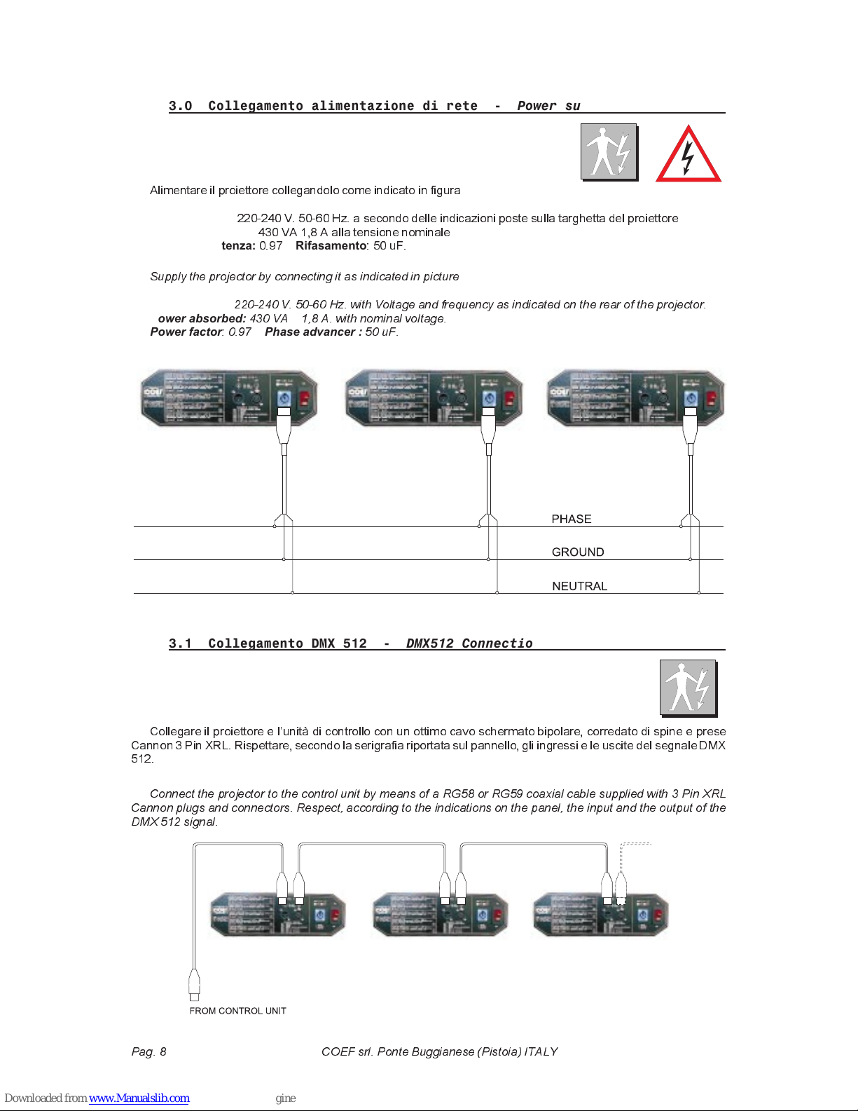
6)
Minimum distance from illuminated objects:
The projector must be positioned in such a way that objects
struck by the light beam are located at least 1,5 metres from the projector objective.
7)
Minimum distance from inflammable materials:
0.1 meters
8)
MAX ambient temperature:
40° C.
1,5 mt.

Pag. 8 COEF srl. Ponte Buggianese (Pistoia) ITALY
3.0 Collegamento alimentazione di rete - Power supply connections
Alimentare il proiettore collegandolo come indicato in figura
Alimentazione:
220-240 V. 50-60 Hz. a secondo delle indicazioni poste sulla targhetta del proiettore
Potenza assorbita:
430 VA 1,8 A alla tensione nominale
Fattore di potenza:
0.97
Rifasamento
: 50 uF.
3.1 Collegamento DMX 512 - DMX512 Connection
Collegare il proiettore e lunità di controllo con un ottimo cavo schermato bipolare, corredato di spine e prese
Cannon 3 Pin XRL. Rispettare, secondo la serigrafia riportata sul pannello, gli ingressi e le uscite del segnale DMX
512.
Supply the projector by connecting it as indicated in picture
Power supply:
220-240 V. 50-60 Hz. with Voltage and frequency as indicated on the rear of the projector.
Power absorbed:
430 VA 1,8 A. with nominal voltage.
Power factor
: 0.97
Phase advancer :
50 uF.
Connect the projector to the control unit by means of a RG58 or RG59 coaxial cable supplied with 3 Pin XRL
Cannon plugs and connectors. Respect, according to the indications on the panel, the input and the output of the
DMX 512 signal.

COEF srl. Ponte Buggianese (Pistoia) ITALY Pag. 9
FUNZIONE 1
Abilita o disabilita il proiettore al comando di
RESET MACCHINA
via DMX.
FUNZIONE 2
Permette di assegnare il proiettore ad un determinato canale DMX di partenza, a seconda dellapparecchiatura
di controllo usata.
FUNZIONE 3
Scambiail senso di direzionedel Canale PAN.Il display
B
indicherà
Std
per Standardo
OPP
per Opposta.
FUNZIONE 4
Scambiail senso di direzionedel Canale TILT.Il display
B
indicherà
Std
per Standardo
OPP
per Opposta.
FUNZIONE 5
Commuta lassegnazione del canale 7 al TILT e 8 al PAN o viceversa.
Std
= 7,PAN 8,TILT
FUNZIONE 6
Cambio colore con otturatore inserito.
Std
= Colore senza otturatore.
FUNZIONE 7
Cambio gobos con otturatore inserito.
Std
= Gobos senza otturatore.
FUNZIONE 8
Indica le ore di funzionamentodella lampada.Resettare a 000 le ore lampada con uno dei due pulsanti
D
o
E
.
FUNZIONE 9
Indica le ore di funzionamento del proiettore.
FUNZIONE t
Viene eseguito un test per ogni canale del proiettore.
FUNZIONE d
Questa funzione dà la possibilità di spengere il display dopo due minuti dal momento in cui è stata inserita. Pre-
mendo un pulsante (
C,DoE
) il display si riaccenderà permettendo modifiche sui settaggi del proiettore.
FUNZIONE h
Pedisponela macchinaperla configurazionea 6, 8 o 9canali. (6=movimentoa 8 bit di risoluzione;8= movimento
a 16 bit di risoluzione; 9= movimento a 16 bit di risoluzione + canale dedicato al dimmer)
FUNZIONE
Permette la rotazione del display a 180° nel caso di fissaggio a soffitto. Il display
B
indicherà
Std
per Standard
o
OPP
per Opposta.
Nel pannello frontale dell
MP250 FRESNEL
troviamo una
sezione dedicata al settaggio del proiettore e alle funzioni ac-
cessorie.
Una chiara legenda permette di comprendere in modo in-
tuitivo le operazioni da compiere per le varie regolazioni e/o
settaggi senza lausilio di un manuale, ma in questa pagina
potrete trovare una esposizione più chiara ed esauriente circa
le procedure di regolazione. Seguendo la figura vediamo in
dettaglio tutte le varie possibilità offerte.
Tutte le operazioni si effettuano tramite i pulsanti
C, D, E
,
indicati rispettivamente come
SELECT
e
SEARCH
.
Premendo
C
ripetitivamente selezioniamo la funzione de-
siderata indicata dal display
A
.
4.0 CODIFICA E FUNZIONI SPECIALI

Pag. 10 COEF srl. Ponte Buggianese (Pistoia) ITALY
On the projectors front panel of the
MP250 FRESNEL
you
will find a section dedicatedto the projectorsetting and acces-
sory functions.
The legend shows in a very simple way how to operate the
different settings and controls, without the need of reading a
manual, but we will give you herewith a clearer explanationof
the settings procedure.
All the operations are executed by means of push-buttons
C, D, E
, indicated with
SELECT
and
SEARCH
.
By repeatedly pushing
C
you can select the desired func-
tion, indicated on the display
A
.
FUNCTION 1
Set on or off the
MACHINE RESET
command by DMX
FUNCTION 2
Gives the possibilityto addressthe projector to a specificDMX startingchannel, accordingto the used controller.
FUNCTION 3
Exchange the way of direction for the PAN channel. Display
B
will show
Std
when Standardor
OPP
when Op-
posite
FUNCTION 4
Exchange the way of direction for the TILT channel. Display
B
will show
Std
when Standardor
OPP
when Op-
posite
FUNCTION 5
It changes over the assignment of the TILT to channel 7 and PAN to channel 8 and vice-versa.
Std
=8 TILT, 7
PAN.
FUNCTION 6
Color change in black-out position.
Std
= without black-out
FUNCTION 7
Gobos change in black-out position.
Std
= without black-out
FUNCTION 8
It will show the lamp life. To reset the time meter to 000, push either push-button
D
or
E
.
FUNCTION 9
It will show the projector s working hours.
FUNCTION t
A test is executed for each projectors channel indicated on display
B
.
FUNCTION d
Gives the possibilityto have the display on or off. You choose to have the display off than the display will remain
alight only for 2 minutesin order to allow you the differentsetting. Press one push botton (
C,DorE
) to have the dis-
play on again.
FUNCTION h
Set the projector for a configuration at 6, 8 or 9 channels. (6= 8 bit movement resolution) (8= 16 bit movement
resolution) (9= 16 bit movement resolution + dedicated DIMMER channel.
FUNZION
If the projector is fixed to the ceiling, this function allows the rotation of the display on 180°. Display
B
will show
Std
when Standard or
OPP
when Opposite.
4.0 SPECIAL FUNCTIONS AND PROJECTOR ASSIGNMENT

COEF srl. Ponte Buggianese (Pistoia) ITALY Pag. 11
5.0 CANALI E VALORI DIGITALI - CHANNELS AND DIGITAL VALUES
SHUTTER / STROBE / DIMMER
0-5 SHUTTER chiuso / closed
6-100 Reg. DIMMER
101-130 Temp. DIMMER da 0 a 100%
131-150 Temp. DIMMER da 100% a 0
151-250 Reg. STROBE
251-255 SHUTTER aperto / open
COLOR 1
0 - 12 White
13 - 29 Yellow
30 - 46 Blue 1
47 - 63 Magenta 1
64 - 80 Green 1
81 - 97 Arancio
98 - 114 Cyano
115 - 131 Pink
132 - 148 Red
149 - 165 Blue 2
166 - 182 Green 2
183 - 199 Wood
200 - 213 Slow rotation
214 - 227 Middle rotation
228 - 240 Fast rotation
241 - 255 Very fast rotation (Rainbow)
COLOR 2
0 - 12 White
13 - 29 Purple
30 - 46 Green 3
47 - 63 Magenta 2
64 - 80 Magenta 3
81 - 97 Dark Red
98 - 114 Blue 3
115 - 131 Blue 4
132 - 148 Dark yellow
149 - 165 Green 4
166 - 182 Filter conv. 3300° K.
183 - 199 Filter conv. 5600° K.
200 - 213 Slow rotation
214 - 227 Middle rotation
228 - 240 Fast rotation
241 - 255 Very fast rotation (Rainbow)
FROST EFFECT
0 - 10 No Frost filter
11 - 241 Reg. Frost Effect
242 - 255 Frost filter to 100%
PAN MOVEMENT
TILT MOVEMENT
SHUTTER / STROBE / DIMMER
0-5 SHUTTER chiuso /closed
6-100 Reg. DIMMER
101-130 Temp. DIMMER da 0 a 100%
131-150 Temp. DIMMER da 100% a 0
151-250 Reg. STROBE
251-255 SHUTTER aperto / open
COLOR 1
0 - 12 White
13 - 29 Yellow
30 - 46 Blue 1
47 - 63 Magenta 1
64 - 80 Green 1
81 - 97 Arancio
98 - 114 Cyano
115 - 131 Pink
132 - 148 Red
149 - 165 Blue 2
166 - 182 Green 2
183 - 199 Wood
200 - 213 Slow rotation
214 - 227 Middle rotation
228 - 240 Fast rotation
241 - 255 Very fast rotation (Rainbow)
COLOR 2
0 - 12 White
13 - 29 Purple
30 - 46 Green 3
47 - 63 Magenta 2
64 - 80 Magenta 3
81 - 97 Dark Red
98 - 114 Blue 3
115 - 131 Blue 4
132 - 148 Dark yellow
149 - 165 Green 4
166 - 182 Filter conv. 3300° K.
183 - 199 Filter conv. 5600° K.
200 - 213 Slow rotation
214 - 227 Middle rotation
228 - 240 Fast rotation
241 - 255 Very fast rotation (Rainbow)
FROST EFFECT
0 - 10 No Frost filter
11 - 241 Reg. Frost Effect
242 - 255 Frost filter to 100%
PAN MOVEMENT
PAN MOVEMENT FINE ADJUSTMENT
TILT MOVEMENT
TILT MOVEMENT FINE ADJUSTMENT
SHUTTER / STROBE
0-5 SHUTTER chiuso / closed
6-250 Reg. STROBE
251-255 SHUTTER aperto / open
COLOR 1
0 - 12 White
13 - 29 Yellow
30 - 46 Blue 1
47 - 63 Magenta 1
64 - 80 Green 1
81 - 97 Arancio
98 - 114 Cyano
115 - 131 Pink
132 - 148 Red
149 - 165 Blue 2
166 - 182 Green 2
183 - 199 Wood
200 - 213 Slow rotation
214 - 227 Middle rotation
228 - 240 Fast rotation
241 - 255 Very fast rotation (Rainbow)
COLOR 2
0 - 12 White
13 - 29 Purple
30 - 46 Green 3
47 - 63 Magenta 2
64 - 80 Magenta 3
81 - 97 Dark Red
98 - 114 Blue 3
115 - 131 Blue 4
132 - 148 Dark yellow
149 - 165 Green 4
166 - 182 Filter conv. 3300° K.
183 - 199 Filter conv. 5600° K.
200 - 213 Slow rotation
214 - 227 Middle rotation
228 - 240 Fast rotation
241 - 255 Very fast rotation (Rainbow)
FROST EFFECT
0 - 10 No Frost filter
11 - 241 Reg. Frost Effect
242 - 255 Frost filter to 100%
PAN MOVEMENT
PAN MOVEMENT FINE ADJUSTMENT
TILT MOVEMENT
TILT MOVEMENT FINE ADJUSTMENT
DIMMER
0 - 10 DIMMER chiuso / closed
11 - 250 Reg. DIMMER
251 - 255 DIMMER aperto / open
CH
1
2
3
4
5
6
7
8
9
6 CANALI - 6 CHANNELS 8 CANALI - 8 CHANNELS 9 CANALI - 9 CHANNELS

Pag. 12 COEF srl. Ponte Buggianese (Pistoia) ITALY
8.0 MANUTENZIONE ORDINARIA - ORDINARY MAINTENANCE
La manutenzione ordinaria sui proiettori
MP250
FRESNEL
è indispensabile per mantenere in perfetta effi-
cenza lapparecchiaturaed evitare linsorgere di difetti come
ad esempio la scarsa resa luminosa del fascio oppure il mo-
vimento irregolare del proiettore o di altre parti rotanti.
Nelle figure vengono evidenziate le parti più sottoposte
ad accumulare polveri e grassi. Procedere alla loro pulizia
con un panno morbido e normali prodotti per la pulizia dei
vetri. Per le figureche mostranocomponentiinterni al proiet-
tore, va precisato che lintervento
dovrà essere effettuato da un ad-
detto alla manutenzionemeccani-
ca che provvederà a ripulire le
parti accessibilisolo allinternodel
proiettore.
The ordinary maintenance is
fundamental for the perfect effi-
ciency of MP250 FRESNEL, in or-
der to prevent any functional
defect as a reduced light beam or
irregularities in the movement of
the projector or of other rotating
parts.
The parts which need more maintenance are shown in the figures. In order to free them from dust or grease,
clean them with a soft cloth and normal products for windows cleaning.
For internal parts, let a technician operate for cleaning.
Nel caso in cui debba essere rimosso il coperchio della testa dellMP250 FRESNEL, sarà sufficenterimuoverele
4 viti di fissaggio con un cacciavite a croce medio. Per rimontare il coperchio seguire le fasi descritte:
A) appoggiare il coperchio sulla testa dellMP250 FRESNEL
B) avvitare solo le 2 viti di fissaggio della parte frontale (obiettivo); la-
sciare libere le due posteriori (lampada).
C) infilare dalla parte anteriore le 2 parti in gomma frontali partendo
dal foro della lente
D) rimuovere il coperchio portalampada ed infilare le due parti in gom-
ma rimanenti per la parte posteriore guidandoli sino alla loro posizione.
E) Bloccare con cura le 4 viti del coperchio.
To let you operate moreeasily, we adviceyou to removethe two top covers of MP250and the two basiscovers.
In order to put again the cover to its place, operate as shown below:
A) Positionate the top cover on the MP250 FRESNEL projector.
B) Screw down the frontal screws (objective); not yet those on the back (lamp).
C) Insert the 2 rubber front parts, guiding them to the end of their position.
D) Remove the lamp cover and insert the two remaining rubber packings, guiding them to the
end of their position.
E) Block carefully the four screws.

COEF srl. Ponte Buggianese (Pistoia) ITALY Pag. 13
8.1 MANUTENZIONE STRAORDINARIA - EXTRAORDINARY MAINTENANCE
Per eseguireuna manutenzionestraordinaria è richiesto linterventodi un manutentoremeccanico sempliceo di
uno qualificato, a seconda del tipo di intervento da eseguire. Per semplicità di intervento consigliamo di rimuovere i
due coperchi della testa del
MP250 FRESNEL
e le le due piastre di copertura della base. In questo modo risulterà
molto più semplice osservarele varieparti da manuteneree/o sostituire.Nellefigure a seguireè possibile osservare
i vari punti indicati come punti di pulizia e nello stesso tempo potremo avere una vista dinsieme della meccanica
montata con tutte le sue parti.
To make an extraordinarymaintenance,it is necessary the presence of a genericor qualified mechanicalopera-
tor, according to the type of the needed intervention. To let you operate more easily, we advice you to remove the
two top covers of MP250and the two basis covers.In this way it will be much more easy to observe the components
to maintain and/or replace. In the following figures its possible to observe the different particulars that have to be
cleaned and, at the same time, the whole mechanical structure mounted with all its components is shown.
Una particolare attenzione andrà dedicata ai
sensori che rivestono un ruolo fondamentale nel
funzionamento dellapparecchiatura.
I sensori sono indispensabili nel momento del
reset generale del proiettore, funzione che se non
eseguita correttamente, pregiudica in modo totale il
funzionamentoregolare del proiettorestesso, alme-
no per quanto riguarda il gruppo associato al sen-
sore stesso.
Es: ad un reset irregolaredella ruota colore,tutti
i colori impostati risulteranno non corrispondenti
alle caratteristiche dichiarate nel capitolo dedicato
ai valori digitali da impostare nel canale DMX per ot-
tenere il colore desiderato.
La stessa identica situazione si presenterà nel
caso della ruota gobos. La sezione otturatore/stro-
bo, non usa sensori per il posizionamento in fase di
reset ma è condizionata da una battuta meccanica
delle palette doscuramento.
You must particularly take care of the sensors
which are really fundamental in the unit working.
The sensors are absolutely necessary when a
general reset of the projector is needed. If this func-
tion is not correctly executed, it will totally compro-
mise the regular working of the projector, at least
for the group referred to the sensor itself.
Es : when theres an irregular reset of the color
wheel, all the setted colors will not correspond to
the colours listed in the chapter about DMX digital
values.
The same situation will occur in the case of the
gobos wheel .
The section shutter/strobo doesnt use sensors
during the reset positioning but its conditioned by a
mechanical beat of the shutter shovels.

Pag. 14 COEF srl. Ponte Buggianese (Pistoia) ITALY
8.2 MANUTENZIONE ELETTRICA/ELETTRONICA - ELECTRONIC MAINTENANCE
Questa sezione è dedicata al dettaglio dei collegamenti elettronici tra la scheda e le parti meccaniche montate
allinterno del proiettore. Queste informazioni risultano indispensabili nel caso in cui la piastra meccanica venga ri-
mossa dallinterno del proiettore per manutenzione e/o riparazione.
I collegamenti effettuati attraverso comodi connettori vengono dettagliati nella figura dove è indicata la corri-
spondenza di un determinato connettore ad una determinata parte componente della piastra meccanica,che incor-
pora i motori e i sensori delle ruote dei vari effetti ( colore, gobos, otturatore ecc. ).
ATTENZIONE!
Un uso improprio di questa documentazione, od effettuato da personale non espressamente
qualificato,può danneggiarein modoirrimediabilele parti elettronichee/o meccanichedel proiettoresu cui vengono
eseguite delle operazioni di manutenzione straordinaria e/o riparazioni.
This section is dedicated in detail to the electronic connections between the card and the mechanical compo-
nents, assembledin the projector.These informationswill be absolutelynecessarywhen the mechanical unit has to
be removed from the projector for maintenance and/or repair.
The connections are made using handy connectors and are detailed in fig. 18 where you can find indications
about the connection between a specific connector and a specific component of the mechanical unit. This includes
the motors and the sensors of the various effects wheels ( color, gobos, shutter etc.).
ATTENTION!
An improper use of this documentation made by not specifically qualified staff can damage irremediably the
electronic and/or mechanical components of the projector.

COEF srl. Ponte Buggianese (Pistoia) ITALY Pag. 15
9.0 PROBLEMI - TROUBLESHOOTING
DIFETTO/PROBLEM CAUSA / CAUSE RIMEDIO / ACTION
Il proiettore non si accende
The projector doesnt switch on
Il proiettore si accende ma non ri-
sponde ai comandi
The projector switches on but
doesnt answer to commands
Proiezione difettosa
Defecting projection
Proiezione con alone
Projection with halo
Il colore o altri effetti non corri-
spondono al valore impostato
The color or other effects
doesnt coincide to the selected
value.
Il movimento del PAN non segue i
valori impostati
The PAN movement doesnt co-
incide to the selected value
- Mancanzadi alimentazionedi rete
- The power supply is not present
- Lampada non funzionante
- The lamp is not working
- Configurazione DMX errata
- Wrong DMX configuration
- Cavi di collegamento difettosi
- Defective cables
- Unità di pilotaggio difettosa
La lente è rotta
The lens is broken
Strati di grasso o polvere sulle lenti
Dust or grease stored on lenses
Strati di grasso e/o polvere su tutte
le parti del proiettore
Dust or grease stored on the all
parts of projector.
Sensori di posizione sporchi
Position sensorwith dust or grease
Sensori di posizione sporchi
Position sensorwith dust or grease
Verificare laccensione della spia sullin-
terruttore di accensione.
Check if the luminous indicator is lighted
or not.
Sostituire la lampada.
Replace the lamp.
Assegnare il valore DMX per il proiettore
Make sure that the projector is correctly
configurated.
Sostituire i cavi o riparare.
Replace or repair the DMX cable.
Controllare lunità di pilotaggio con altri
proiettori funzionanti.
Chek the control unit by means of other
working projectors.
Intervento di assistenza tecnica.
Technical aid is required.
Controllare che la lente non sia rotta.
Ceck that the lens are not broken.
Rimuovere la polvere e/o grasso sulle len-
ti.
Remove dust or grease stored on lenses.
Effettuare una accurata pulizia di tutte le
parti del proiettore (vedi capitolomanuten-
zione)
Carefully clean the optical group lenses
and the projector components (see Main-
tenance chapter)
Effettuare una accurata pulizia di tutte le
parti del proiettore (vedi capitolomanuten-
zione)
Carefully clean the optical group lenses
and the projector components (see Main-
tenance chapter)
Intervento di assistenza tecnica
Technical aid is required.
Effettuare una accurata pulizia di tutte le
parti del proiettore (vedi capitolomanuten-
zione)
Carefully clean the optical group lenses
and the projector components (see Main-
tenance chapter)
Intervento di assistenza tecnica
Technical aid is required.

Pag. 16 COEF srl. Ponte Buggianese (Pistoia) ITALY
10.0 DICHIARAZIONE DI CONFORMITA’ - CONFORMITY DECLARATION
Declaration of CE Conformity
We, Manufacturer/Importer
COEF srl.
Via Albinatico, 80-82
51019 Ponte Buggianese (Pistoia)
ITALY
Declare that the product
MP250 Optic / Fresnel
Is in conformity with
In accordance with 89/336 EEC-EMC Directive
and
With the actual required safety standards
in accordance with LVD 73/23 EEC
EN 61000-3-2
EN 60555-2
EN 61000-3-3
EN 60555-3
EN 50081-1
EN 50082-1
EN 55081-2
EN 55082-2
ENV 55104
EN 61547
EN 60598-1
EN 60598-2-17
Disturbances in supply systems caused by
household appliances and similar electri-
cal eqipment Harmonics
Disturbances in supply systems caused by
household appliances and similar electri-
cal eqipment Voltage fluctuations
Generic emission standard Part 1:
Residual, commercial and light industry
Generic immunity standard Part 1:
Residual, commercial and light industry
Generic emission standard Part 2:
Industrial environment
Generic immunity standard Part 2:
Industrial environment
Immunity requirements for household ap-
pliances tols and similar apparatus
Equipment for general lighting purposes
(immunity)
Light fixtures
General instructions and tests
Light fixtures. General instructions and
tests. Equipment fixtures for stages, TV
and cinema studios
EN 55011
EN 55013
EN 55014
EN 55015
EN 55022
EN 55020
DIN VDE 0855
PART 10
PART 12
EN 60065
EN 60335
Limits and methods of measurement of ra-
dio disturbance characteristics of indu-
strial, scientific and medical (ISM) high
frequency equipment
Limits and methods of measurement of ra-
dio disturbance characteristics of broad-
cast receivers and associated equipment
Limits and methods of measurement of ra-
dio disturbance characteristics of hou-
sehold electrical appliances, portable tools
and similar electrical apparatus
Limits and methods of measurement of ra-
dio disturbance characteristics of fluore-
scent lampsand luminaries
Limits and methods of measurement of ra-
dio disturbance characteristics of informa-
tion technology equipment
Immunity from radio interference of broad-
cast receivers and associated equipment
Cabled distribution systems; Equipment
for receiving and/or distribution from sound
and television signals
Safety requirements for mains operated
electronic and related apparatus for hou-
sehold and similar general use
Safety of household and similar electrical
appliances
Name: Alfonso Ceccarelli
Position: Managing Director
Signature:
Date: Ponte Buggianese, 5 October 1998

COEF srl. Ponte Buggianese (Pistoia) ITALY Pag. 17
Filter
3A.
THERMAL
SWITCH
L
T
11.0 SCHEMA ELETTRICO - ELECTRIC DIAGRAM

Pag. 18 COEF srl. Ponte Buggianese (Pistoia) ITALY
12.0 DIMENSIONI - DIMENSIONS
438.00
350.00
450.00
438.00

COEF srl. Ponte Buggianese (Pistoia) ITALY Pag. 19
13.0 NOTE - NOTES

Printed in December 1998
COEF sr. Ponte Buggianese (Pistoia) ITALY
®
COEF srl.
Via Albinatico, 80-82
51019 Ponte Buggianese (Pistoia)
ITALY
Tel. ++39-0572-636536 a.r. Fax ++39-0572-636535
Realized by PC CAD & VIDEO
Other manuals for MP250 FRESNEL
2
Table of contents
Popular Speakers manuals by other brands

Ground Zero
Ground Zero Competition Series owner's manual

Sony
Sony S-AIR AIR-SA50R Specifications

Federal Signal Corporation
Federal Signal Corporation DS100 Description, Specifications, and Installation Manual

Electro-Voice
Electro-Voice DL18X Specification sheet

Behringer
Behringer Eurolive VP2520 quick start guide

CONTINENTAL EDISON
CONTINENTAL EDISON CECHFBT20B3 Instruction booklet