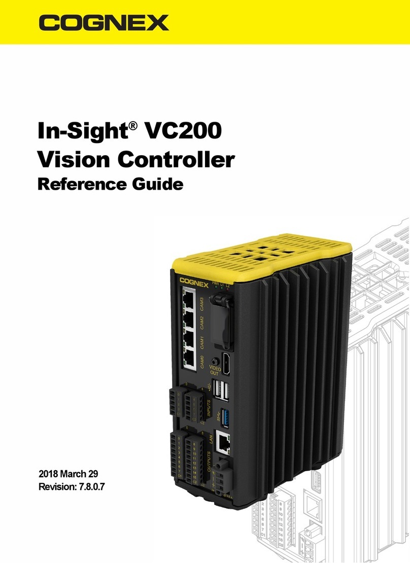
Cognex In-Sight VC200 User manual

In-Sight®VC200
Vision Controller
Manual
2018 March 29
Revision: 7.8.0.7

Regulations/Conformity
Note: For the most up-to-date CE declaration and regulatory conformity
information, please refer to the Cognex online support site:
http://www.cognex.com/Support.
Safety and Regulatory
Manufacturer Cognex Corporation
One Vision Drive
Natick, MA 01760 USA
Regulatory Model 1AAL
FCC FCC Part 15, Class A
This device complies with Part 15 of the FCC Rules. Operation is subject to the
following two conditions: (1) this device may not cause harmful interference; and
(2) this device must accept any interference received, including interference that
may cause undesired operation. This equipment generates, uses, and can radiate
radio frequency energy and, if not installed and used in accordance with the
instruction manual, may cause harmful interference to radio communications.
Operation of this equipment in a residential area is likely to cause harmful
interference in which case the user will be required to correct the interference at
their own expense.
KCC Regulatory Model 1AAL: MSIP-REM-CGX-1AAL
NRTL TÜV SÜD AM SCC/NRTL OSHA Scheme for UL/CAN 61010-1.
CB TÜV SÜD AM, IEC/EN 61010-1. CB report available upon request.
EU RoHS Compliant to the latest applicable Directive.
1

China RoHS
Hazardous Substances 有害物质
Part Name
部件名称 Lead (Pb)
铅Mercury
(Hg)
汞
Cadmium
(Cd)
镉
Hexavalent
Chromium
(Cr (VI))
六价铬
Polybrominated
biphenyls (PBB)
多溴联苯
Polybrominated
diphenyl ethers
(PBDE)
多溴二苯醚
Regulatory
Model 1AAL
X O O O O O
This table is prepared in accordance with the provisions of SJ/T 11364.
这个标签是根据SJ / T 11364 的规定准备的。
O: Indicates that said hazardous substance contained in all of the homogeneous materials for this part is below the
limit requirement of GB / T26572 - 2011.
表示本部件所有均质材料中含有的有害物质低于GB / T26572 - 2011 的限量要求。
X: Indicates that said hazardous substance contained in at least one of the homogeneous materials used for this
part is above the limit requirement of GB / T26572 - 2011.
表示用于本部件的至少一种均质材料中所含的危害物质超过GB / T26572 - 2011 的限制要求。
2

For European Community Users
Cognex complies with Directive 2012/19/EU OF THE EUROPEAN PARLIAMENT
AND OF THE COUNCIL of 4 July 2012 on waste electrical and electronic equipment
(WEEE).
This product has required the extraction and use of natural resources for its
production. It may contain hazardous substances that could impact health and the
environment, if not properly disposed.
In order to avoid the dissemination of those substances in our environment and to
diminish the pressure on the natural resources, we encourage you to use the
appropriate take-back systems for product disposal. Those systems will reuse or
recycle most of the materials of the product you are disposing in a sound way.
The crossed out wheeled bin symbol informs you that the product should not
be disposed of along with municipal waste and invites you to use the appropriate
separate take-back systems for product disposal.
If you need more information on the collection, reuse, and recycling systems, please
contact your local or regional waste administration.
You may also contact your supplier for more information on the environmental
performance of this product.
3

Precautions
Observe these precautions when installing the vision controller to reduce the risk of
injury or equipment damage:
lThe vision controller is intended to be supplied by a NRTLlisted power
supply with a minimum output rated 24VDC, 3.5A and must be used with
the Cognex-supplied 24VDC power connector. Any other voltage creates a
risk of fire or shock and can damage the components. Applicable national
and local wiring standards and rules must be followed. Wire and
connections must be in accordance with these instructions, the National
Electrical Code and applicable national and local wiring standards and rules.
lTo reduce the risk of damage or malfunction due to over-voltage, line noise,
electrostatic discharge (ESD), power surges, or other irregularities in the
power supply, route all cables and wires away from high-voltage power
sources.
lDo not install Cognex products where they are directly exposed to
environmental hazards such as excessive heat, dust, moisture, humidity,
impact, vibration, corrosive substances, flammable substances, or static
electricity.
lThe In-Sight vision controller does not contain user-serviceable parts. Do
not make electrical or mechanical modifications to In-Sight vision controller
components. Unauthorized modifications may void your warranty.
lChanges or modifications not expressly approved by the party responsible
for regulatory compliance could void the user’s authority to operate the
equipment.
lService loops should be included with all cable connections.
4

lCable shielding can be degraded or cablescan be damaged or wear out
more quickly if a service loop or bend radius is tighter than 10X the cable
diameter. The bend radius must begin at least six inches from the
connector.
lRemove power from the vision controller before connecting or
disconnecting any cables or the I/O terminal blocks.
lThe maximum torque that can be applied to the I/O terminal connectors is
0.25 Nm (2.2 in-lb). Applying torque above this limit can damage the
connectors.
lRemove power from the vision controller before connecting or
disconnecting the 24VDC power connector.
lThe maximum torque that can be applied to the 24VDC power connector is
0.6 Nm (5.3 in-lb). Applying torque above this limit can damage the
connector.
lThis device is a business-use (Class A) EMC-compliant device. The seller
and user are advised to be aware of this fact. This device isintended for use
in areas outside the home.
lThisdevice should be used in accordance with the instructions in this
manual.
lAll specifications are for reference purpose only and may be changed
without notice.
5

Open Source Libraries
The In-Sight®VC200 vision controller uses third-party open source software, whose
licenses are described in the click-accept agreement that ispart of the In-Sight VC
Explorer software installation.
6

Installation
Thissection describes the connection of the vision controller to its standard and
optional components.For a complete list of options and accessories, contact your
Cognex sales representative.
Installation procedures and specifications are presented in detailin the In-Sight®
VC200 Vision Controller Reference Guide.
Note: Cables are sold separately.
CAUTION:All cable connectors are “keyed” to fit the connectors on the vision
controller; do not force the connections or damage may occur.
Mount the Vision Controller
The vision controller provides mounting holes for attachment to either a bottom or
backside mounting surface.
Note: The vision controller may be optionally mounted using the accessory
wall mounting bracket (BKT-WALL-VC200-01) or to a 15mm DINrail, using
the accessory DIN rail mounting bracket (BKT-DIN-VC200-01).The DIN rail
mounting bracket accessory is not suitable for a 7.5mm profile DIN rail. Please
contact your Cognex sales representative for more information.
7

CAUTION:
lThe vision controller must be mounted in a vertical orientation with the
top of the controller up, and cannot be mounted in a horizontal
orientation.
lTo ensure sufficient ventilation, the vision controller must be mounted
with sufficient clearance. If mounting to the bottom surface, 50mm of
clearance is required above and on both sides of the vision controller.
If mounting to the backsurface or using the accessory wall mounting
bracket or DINrail mounting bracket, 24.5mm of clearance is
required above, below and on both sides of the vision controller. If an
adjacent device also produces heat, additional space or cooling is
required if air space around the vision controller exceeds 45°C
(113°F).
lAllow sufficient clearance and strain relief for wires and cables
connected to the vision controller.
1. Drill the clearance holes for the mounting fasteners per the defined bolt
pattern. The vision controller mounting hole screw thread is M4 x 0.7.
2. Align the holes on the mounting surface with the mounting holes on the
vision controller.
8

3. Insert and tighten the mounting screws; the maximum torque is 2 Nm
(18in-lb).
CAUTION:The length of the screws used depends on the depth of
the mounting surface; thread engagement of the screws must be
8mm-10mm.
9

Connect the ISC-7800 Series Camera
The ISC-7800 series camera's PWRconnector supplies power to the camera and
provides access to the camera's acquisition trigger and strobe output. The camera's
ENET connector provides an Ethernet connection. Refer to the ISC-7800 Series
Camera Reference Guide for complete camera installation steps and specifications.
CAUTION:Cognex recommends only cold-plugging the camera; turn the
vision controller power off when connecting or disconnecting the camera.
1. Verify the camera's 24VDC power supply being is unplugged and not
receiving power.
2. Optionally, connect the Breakout cable's I/O wires to an appropriate device
(for example, a trigger sensor or strobe light).
Note: I/O wiring or adjustments to I/O devices should be performed
when the camera is not receiving power.
10

3. Attach the Breakout cable's +24VDC (Red wire) and GND (Blackwire) to
the corresponding terminals on the power supply.
CAUTION:
lUse a UL or NRTL listed power supply with a 24VDC output
rated for at least 2A continuous and a maximum short circuit
current rating of less than 8A and a maximum power rating of
less than 100VA and marked Class 2 or Limited Power
Source (LPS).
lNever connect voltages other than 24VDC. Always observe
the polarity shown.
Note: Unused wires can be clipped short or tied back using a tie made
of non-conductive material.Keep all bare wires separated from the
+24VDC wire.
4. Connect the Breakout cable's M12 connector to the camera's PWR
connector.
5. Connect the Ethernet cable’s M12 connector to the camera's ENET
connector.
11

6. Connect the Ethernet cable's RJ-45 connector to one of the vision
controller's CAM ports.
Note: If using a vision controller that supports a two camera
configuration, connect the camera Ethernet cables to the vision
controller's CAM0 and CAM1 ports.
12

Connect the ISC-8000 Series Camera
The ISC-8000 series camera's I/O connector provides connection to the camera's
acquisition trigger and strobe output. The camera's ENET connector provides an
Ethernet connection and Power over Ethernet (PoE) to the camera. Refer to the
ISC-8000 Series Camera Reference Guide for complete camera installation steps
and specifications.
CAUTION:Cognex recommends only cold-plugging the camera; turn the
vision controller power off when connecting or disconnecting the camera.
1. Optionally, connect the Breakout cable's M8 connector to the camera's I/O
connector.
CAUTION:A ferrite is included with the In-Sight 8405 camera
standard components. To reduce emissions, the ferrite must be
attached to the Breakout cable, adjacent to the strain relief on the
cable.
13

2. Connect the Breakout cable's trigger and strobe wires to an appropriate
device (for example, a trigger sensor or strobe light).
Note:
lI/O wiring or adjustments to I/O devices should be performed
when the camera is not receiving power.
lThe Ethernet cable should be unplugged or the PoE source
powered down before making adjustments to the
connections at the far end of the Breakout cable.
lUnused wires can be clipped short or tied back using a tie
made of non-conductive material.
3. Connect one end of the Ethernet cable to the camera's ENET connector. If
installing the In-Sight 8405 camera and using a compatible horizontal
screw-locking Ethernet cable, use a screw driver to tighten the connector
screws until snug, to secure it to the camera. The screws must be tight to
ensure a reliable connection.
CAUTION:
lThe Ethernet cable must be shielded. For the In-Sight 8405
camera, Cognex strongly recommends Cat 6 or Cat 7
Ethernet cables with S/STP shielding.
lThe Ethernet cable shield must be grounded at the far end.
lThe vision controller's CAM ports provide Power over
Ethernet (PoE) to supported Cognex devices; connecting
other PoE devices to these ports could damage the vision
controller or the PoE device.
14

4. Connect the other end of the cable to one of the vision controller's CAM
ports.
Note: If using a vision controller that supports a two camera
configuration, connect the camera Ethernet cables to the vision
controller's CAM0 and CAM1 ports.
15

Connect the DS900 Series Sensor
The DS900 series sensor's Ethernet connector provides an Ethernet connection
and Power over Ethernet (PoE) to the sensor. The sensor's multifunction port
provides access to I/O connections.
WARNING:The DS900 series sensors are designated as a Class 2M laser
product. These laser products can be hazardous. Please refer to the DS900
Series and DS1000 Series Sensor Reference Guide for important instructions
on their safe use.
CAUTION:
lCognex recommends only cold-plugging the sensor; turn the vision
controller power off when connecting or disconnecting the sensor.
lThe vision controller's CAM ports provide Power over Ethernet (PoE)
to supported Cognex devices; connecting other PoE devicesto these
ports could damage the vision controller or the PoE device.
1. Optionally, connect the terminated end of the Multifunction cable to the
DS900 series sensor's Multifunction port. Connect the I/O wires to the
applicable I/O device.
CAUTION:The Multifunction cable's PWR (Red) and GND (Blue)
flying lead wires must not be connected to any external point or to
each other.
2. Connect the Ethernet cable's M12 connector to the DS900 series sensor.
16

3. Connect the Ethernet cable's RJ-45 connector to one of the vision
controller's CAM ports.
Note: Your specific configuration and firmware version may support
between 1 and 4 sensors. Regardless of how many sensors your
device supports or how many sensors you connect, you should
alwaysconnect the first sensor to port 0, the second sensor to port 1,
and so on.
17

Connect the DS1000 Series Sensor
The sensor's 24VDC Power + I/O + Encoder connector provides access to power
and I/O connections. The DS1000 series sensor's Ethernet connector provides an
Ethernet connection.
WARNING:The DS1000 series sensors are designated as a Class 2M laser
product. These laser products can be hazardous. Please refer to the DS900
Series and DS1000 Series Sensor Reference Guide for important instructions
on their safe use.
CAUTION:Cognex recommends only cold-plugging the sensor; turn the
vision controller power off when connecting or disconnecting the sensor.
18

1. Verify that the DS1000 power supply is unplugged and not receiving power.
2. Attach the Power and I/O Breakout cable's +24VDC (Red wire) and GND
(Black wire) to the corresponding terminals on the power supply. Connect
the cable or connector shield to earth ground.
CAUTION:
lUse a listed power supply with an output rated 24VDC, at
least 500 mA, and marked Class 2, Limited Power Source
(LPS). Any other voltage creates a risk of fire or shock and
can damage the sensor.
lNever connect voltages other than 24VDC. Always observe
the polarity shown.
Note:
lPins 1, 2, 3, and 4 may be used for an encoder connection.
The configuration that you set for your sensor using the
Cognex software determines how those lines are used.
lCognex recommends unused encoder connections be tied
to ground. If encoder signal inputs are left unconnected and
your Cognex software is configured to use an encoder, the
behavior of the encoder counter is undetermined.
19
Other manuals for In-Sight VC200
2
Table of contents
Languages:
Other Cognex Controllers manuals