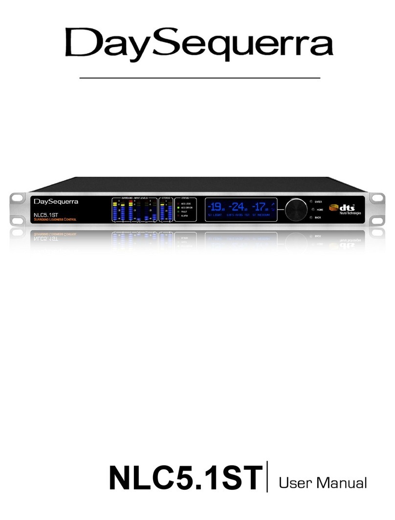
DaySequerra iLC 2ST User manual

iLC 2ST
User Manual

2
iLC2ST User Manual
Welcome
Thanks for purchasing the DaySequerra ILC2ST. Differences in audio levels between TV programs, or
between programs and commercials, are a constant annoyance to viewers. ILC2STST permits
broadcasters to establish a consistent loudness level across all audio programming and minimize
viewer complaints.
We design and build all of our DaySequerra products to be completely reliable and easy to use, so you
can concentrate on producing great sounding broadcasts, not struggling with complicated equipment or
difficult to use product manuals.
While the ILC2ST has been designed to be straightforward to use, we do suggest that you spend a few
minutes familiarizing yourself with the features and operational functions that are contained in this
manual.
DaySequerra has been building broadcast quality products since 1989. The technology developed for
the ILC2ST, and all of our products, has evolved through a process of user feedback, extensive
listening, field-testing and careful refinement.
In the event that you encounter any technical or operational difficulties with this or any DaySequerra
product, please feel free to contact us at +1-856-719-9900. Our office hours are from 9 to 5 ET,
Monday through Friday; or you can email your questions to: info@daysequerra.com.
Also, please remember to visit our website www.daysequerra.com for warranty registration and the
latest DaySequerra product information.
We have worked hard to ensure that your DaySequerra ILC2ST will reliably serve you for years to
come. With a modular design and upgradeable firmware, your new unit is easy to install and use right
out of the box.
We sincerely hope our products help you achieve a new level of excellence in your work!
David V. Day
and the DaySequerra Team

iLC2ST User Manual
3
Table of Contents
Important Safety Information
4
Homescreen
16
Service Information
4
Loudness Control Presets
26
Technical Specifications
5
Remote Dashboard
29
Introduction
7
Remote Dashboard Configuration
31
Measuring Loudness
8
Using Remote Dashboard
33
Installation
11
Firmware Update
37
Front Panel
12
Maintaining an Accurate Clock
38
Rear Panel
13
Remote Dashboard Troubleshooting
39
Programming Menus & Functions
15
Warranty Information
40
All rights reserved DaySequerra Corp. Copyright 2011.
All logos and trademark used herein are the property of their respective owners.
Specifications subject to change.
iLC2ST User Manual Revision A.1 for firmware 4.01.01.
ILC2ST Key Features
•Real-time adaptive loudness control delivers ITU BS.1770 compliant
loudness without “squashing” the sound
•Two independent stereo loudness controllers each with full-featured
ITU.BS1770 loudness meter
•Exclusive look-ahead technology makes gain corrections imperceptible
•Optional analog I-O, HD-SDI I-O and redundant auto-switching power
supply
•GPI-switched user presets perfect for DayPart programming
•10/100 Base-T Ethernet interface for long-term logging and field software
updates

4
iLC2ST User Manual
Important Safety Information
•Indoor use only. Not for use in wet or damp environments.
•Maximum Relative Humidity: <80%
•Class I Equipment (grounded type)
•Electrical rating: 100-120/220-240V~50-60Hz 18W
•Internal circuit breaker for continuous short circuit protection
•AC Mains supply voltage fluctuations are not to exceed +10% of the nominal voltage
•Operations temperature range -40°C to 70°C
•Maximum altitude: 3000m (9843ft)
•Equipment suitable for continuous operation
•Weight: 3.6kg (8lbs) equipment only; 6.1kg (13.5lbs) shipping
Important Note: Please connect your ILC2ST to an uninterruptible power supply (UPS) to
provide other protection against power surges and brownouts.
The DaySequerra ILC2ST is subjected to a strong RFI field, such as those emitted from portable two
way radios, the front panel display may “blank out”. To restore the display without rebooting the unit,
turn the rotary encoder to activate the main menu, and then press HOME. If the keylock is enabled, you
will have to deactivate it by pressing the ENTER key followed by BACK.
Service Information
The DaySequerra ILC2ST contains no user serviceable components inside the unit. Please contact
DaySequerra for repair and upgrade information. In the event that your unit needs to be returned to the
factory, contact us for a return authorization number. Please visit www.daysequerra.com and
register your new ILC2ST so we can keep you informed of the latest hardware and software
updates.
The lightning flash with arrowhead symbol is
intended to alert the user to the presence of un-
insulated “dangerous voltages” within the product’s
enclosure that may be of a sufficient level to cause
harm.
The exclamation point within a triangle is intended
to alert the user to the presence of important
operating and maintenance instructions within the
product literature.
Exposed portions of the power supply assembly are
electrically live. To reduce risk of electric shock, the
power cord must be disconnected when the power
supply assembly is removed. For continued protection against electric shock, a correctly wired
and grounded (earthed) three-pin power outlet must be used. Do not use a ground-lifting
adapter and never cut the ground pin on the three-prong plug. The ground terminal of the power
plug is connected directly to the chassis of the unit.

iLC2ST User Manual
5
Technical Specifications
Inputs
2 AES-3 Stereo Inputs
Optional HD/SDI Input and pass-through
Outputs
2 Transformer-isolated AES-3 Stereo Outputs
Audio Input and Output
Interface
AES/EBU, 75ohm, unbalanced BNC
Optional HD/SDI Input and pass-through
Optional Analog I/O
Loudness Measurement and
Correction
ITU-R BS.1770/1 Industry Standard Loudness Measurement
DTS Neural Loudness Measure
DTS Neural Loudness Control
Sample Rate
48 kHz
Latency [1]
16 ms
GPI Alarms
DB-9 female connector, 0-5VDC TTL
2 DayPart Inputs per channel; Alarm at fault Outputs
Ethernet/Remote Dashboard
10/100-BASE-T for field software updates, logging and remote
control
Remote Dashboard – Windows app for compliance logging
and remote control
Dimensions and Weight
19” (482mm)W x 8” (203mm)L x 1.75” (44mm)H
7 lbs (3.2 kg)
Regulatory:
North America: Designed to Comply with FCC Class A part 15
Europe: LV Directive 73/23/EEC and EMC Directive
89/336/EEC; CE Mark (EN 55022 Class A, EN55024);
RoHS and WEEE compliant
Power Supply
Optional - Dual redundant
Auto-sensing 100-240V, 50-60Hz
EMI suppressed male IEC320 C14 connectors
Warranty
One year, limited parts and labor

6
iLC2ST User Manual
FCC Part 15 Regulatory Statement
This equipment has been tested and found to comply with the limits for Class A digital device pursuant
to Part 15 of the FCC Rules. These limits are designed to provide reasonable protection against
harmful interference when the equipment is operated in a commercial environment. This equipment
generates, uses, and can radiate radio frequency energy and, if not installed and used in accordance
with the instruction's manual, may cause interference to radio communications. Operation of this
equipment in a residential area is likely to cause interference in which case the user will be required to
correct the interference at their own expense. The user is cautioned that changes and modifications
made to the equipment without approval of the manufacturer could void the user's authority to operate
this equipment. The user should use only shielded and/or grounded cables to combat sources of
interference.
Environmental Preservation Efforts
This equipment has been designed and built by DaySequerra
corporation to give many years of trouble free service and is backed
by our three year warranty and commitment of providing the best
customer support. When the time comes to retire your product from
service, it should be disposed of in accordance with local codes or ordinances. Do not
discard with household or commercial waste.
DaySequerra products are manufactured with the environment in mind. The directive on the restriction
of the use of certain hazardous substances in electrical and electronic equipment (2002/95/EC) restricts
the use of six specific hazardous materials in the manufacture of various types of electronic and
electrical equipment. Following this directive prevents these toxic substances from entering our
environment after disposal.

iLC2ST User Manual
7
Introduction
Broadcasters need a solution to effectively measure, and ultimately control the abrupt changes in
loudness that sends viewers diving for their remote controls during commercial breaks and action
scenes. The DaySequerra ILC2ST Intelligent Loudness Control delivers ATSC A/85 CALM, ARIB – B32
and EBU R128 loudness compliance for stereo broadcasts worldwide in a cost-effective feature-rich 1
RU package.
The iLC2ST’s adaptive look-ahead loudness control eliminates viewer complaints without damaging the
original mix; build-in ITU.BS1770 loudness meter ensures regulatory compliance. The iLC2ST’s
Remote Dashboard provides remote control, monitoring and logging.
ILC2ST then uses the proprietary DTS-Neural Loudness Control, an advanced loudness-leveling
algorithm, to apply the appropriate gain or attenuation to maintain the broadcaster-defined loudness
level. The resulting audio has a naturally open, dynamic quality without the annoying side-effects of
traditional energy-based volume management solutions.
Loudness is a perceptual property of an audio signal when it is reproduced acoustically. It is a complex
non-linear function of amplitude, frequency and bandwidth. Current audio level meters measure the
level of audio signals expressed as the amplitude of the signal - either the RMS (root mean square)
voltage of an electrical signal or the sound pressure of an acoustical signal. Neither of these
measurements, although widely accepted, provides accurate indications of how viewers will perceive
the loudness of the audio programming.
The DTS NLM algorithm uses a perceptual model of human hearing to more accurately detect spectral
and density differences, inter-channel relationships and temporal overlaps in any audio content,
resulting in a more accurate perceived loudness measurement over time. This proprietary algorithm
was developed by after extensive research into human hearing and perceived loudness.
To improve system reliability and up-time, ILC2ST uses a robust DSP-based processing platform rather
than a PC-based approach to completely avoid broadcast disruptions caused by operating system
lockups. An Ethernet interface provides long-term logging and field software updates capability. An
optional factory-installed HD/SDI module will allow for measurement of 8 channels of program audio
from group 1 or group 2 with user specified mappings within the group. A set of user-definable alarms
can alert an operator of input loss, signal clipping and high or low signal levels referenced to the
desired loudness level.
When ILC2ST is used ahead of an AC3 (Dolby Digital) transmission, the target loudness level will also
match the Dialnorm metadata information, thus providing consistent, enjoyable audio for all viewers.
Whether pre-screening content at an ingest point or controlling the loudness of a broadcast air-chain,
the DaySequerra ILC2ST is your key to reduce viewers complaints and improve audience satisfaction.

8
iLC2ST User Manual
Measuring Loudness
Human perception of the sensation of an audio signal is properly called “loudness”. As early as 1933,
research by Fletcher and Munson showed that human hearing sensitivity is largely based upon the
frequency of the sound, as well as the sound pressure level (SPL). As humans do not hear sound using
standard measures of intensity, measuring loudness based upon SPL or the root mean square (RMS)
voltage of the electrical signal will not agree with human perception. The Fletcher/Munson Equal
Loudness Curves show the limits human sensitivity of certain frequencies, especially low frequencies
(bass) at lower sound levels (Fletcher & Munson, 1933).
In order to create a loudness measure that more accurately represents the human perception of
loudness, frequency weighting (or equalization curves) are placed ahead of power measurements. This
introduces the measures Leq(A), Leq(B), Leq(C) and Leq(M) – with ‘Leq’attempting to relate the
‘L’oudness of an ‘eq’uivalent amount of energy in a standard signal, typically a 1 kHz sine wave. The
most current weighting standard, ITU-R BS.1770 produces results known as LKFS that are referenced
to a dB FS scale. While certain Leq(x) measures match more closely to human loudness perception
than traditional SPL or RMS measurements, there are still many broadcast content types that cannot be
measured correctly with a Leq(x) or LKFS weighting method.
For example, a narrowband signal may be perceived to sound softer than an equally intense wideband
sound, depending on the relationship between rendering level, absolute threshold and signal content.
Additionally, content with large amounts of low-frequency energy is often inaccurately measured by
BS.1770 due to heavy low-frequency roll off (see weighting curves). This measurement will often vary
from a subjective measure, especially in the short term; however this variance is acceptable in a long-
term measurement, as the values are smoothed over many seconds, minutes or hours. Small
deviations between the instantaneous perception of loudness is often acceptable when using a meter
solution to measure the loudness, as the meters usually offer an audio visualization method that human
operators can use. Combined with their ears, the operator can make any decisions about any corrective
action required.
Fletcher/Munson Equal Loudness Curves

iLC2ST User Manual
9
Weighting Curves
To achieve a more accurate loudness measurement, the method should include critical bands in the
measurement. Critical bands describe auditory filters within the human cochlea. (J. Allen, 2010). To
illustrate this, a subject is presented with a single tone of a certain energy level, and more tones are
added with equal energy in the critical bands – the total signal energy is kept constant regardless of the
number of tones. If changing from one to two tones, the energy of each of the two tones is exactly half
of that of the single tone. While the amount of audio energy never changes, the perceived loudness
increases as the energy spectrum spreads out across more tones (Johnston, 2006).
J. Allen Cochlea Filters (2010)

10
iLC2ST User Manual
Bronwyn Jones and Emil Torick created a revised CBS loudness meter in the early 1980s that
consisted of eight filters, each covering three critical bands. This approach did prove to deliver better
subjective modeling than traditional SPL or RMS measurements (Jones & Torick, 1982).
In 2004, Nielsen and Skovenborg published an AES paper that expanded upon the ideas of critical
band loudness measures. This paper introduced a method called HEIMDAL, which separated spectra
into nine bands via an octave filter band. While the HEIMDAL multi-band model did not achieve the
complexity of cochlear modeling as shown by J. Allen, the method had the lowest error compared to
any preceding loudness models (Nielsen & Skovenborg, 2004).
Despite the clear benefits of critical band analysis in loudness measurement, there are very few
methods currently available to measure loudness this way in real-time for broadcast applications -- the
extra processing required to accomplish it have prevented widespread adoption. DTS Neural Loudness
Measure is the first real-time perceptual loudness measurement product available that embraces this
advanced approach to loudness measurement.
Absolute Error (dB) of various loudness measures
Critical band comparison between loudness measures

iLC2ST User Manual
11
Work Cited
1. Fletcher, H. & Munson, W. A. (1933). Loudness, its Definition, Measurement, and Calculation.
2. Allen, J (2010 May 20). Nonlinear Cochlear Signal Processing.
3. Johnston, J. (2006). Loudness Tutorial.
4. Jones, B. L. & Torick, E. L. (1982). A New Loudness Indicator for Use in Broadcasting.
5. Nielsen, S. H. & Skovenborg, E. (2004). Evaluation of Different Loudness Models with Music
and Speech Material.
Installation
Immediately upon receiving your ILC2ST, please make a careful inspection for any shipping damage. If
damage is found or suspected, please notify the carrier at once and then contact your dealer. ILC2ST is
shipped in one carton, which contains: the ILC2ST unit and two NEMA5-15P to IEC320 C13 AC power
cables.
We strongly encourage you to save the shipping carton and shipping materials supplied with your
ILC2ST. They are specially designed to properly protect your ILC2ST, and in the event that you need to
return it for service, only these OEM shipping materials can ensure its safe return to our factory.
We provide a limited 1-year warranty on all of our products; however, if you don’t register your unit, it is
impossible for us to contact you to notify you when important software upgrades become available.
Please take a few minutes to complete the warranty registration form on our website,
www.daysequerra.com.
Each Leq(x) revision results in a different level of correlation between the objective measure and
the human listener’s assessment of loudness. The lowest mean error score was achieved by the
Neural Loudness Measure

12
iLC2ST User Manual
Rack Mount Installation
The ILC2ST chassis has four rack mounting holes and has been designed to fit in a standard 1RU
space. Plastic ‘finishing’ washers are recommended to protect the painted surface around the mounting
holes. Locate the air vents on each side of the unit, and be sure to keep them clear so the unit may
have adequate ventilation.
Power Connection
The AC power cable supplied with ILC2ST must be connected from the IEC320 power entry module to
an AC mains outlet with a functional earth ground connection. For protection against electric shock and
electro-magnetic interference, do not plug the power cable into a ground-lifting adapter or remove the
cable’s grounding pin. If in doubt, please consult a qualified electrician.
ILC2ST is designed with reliability in mind and contains two auto-switching power supplies. Please
connect ILC2ST to an uninterruptible power supply (UPS) to protect against power surges and low-
voltage conditions. For maximum redundancy, connect each power supply to a separate UPS on
different power circuits. ILC2ST may be combined with other devices on the output of the UPS as long
as the total load is within the UPS’ capacity. Consult your UPS manual for details.
ILC2ST will automatically power up when AC power is applied. If AC line power is lost or momentarily
interrupted, ILC2ST will revert to its previous state when the power is restored. Hard- bypass relays will
pass through audio directly to the outputs when the unit is unpowered. However, audio cannot be de-
embedded from the HD/SDI input and bypassed to the AES outputs while the unit is unpowered.
Front Panel Controls and Indicators
Status Indicators
Alarms - Red LED indicator illuminates when ILC2ST has an alarm notification.
Audio - Green LED indicator illuminates when a valid signal is present.
Network - Blue LED indicator illuminates when ILC2ST has a successful network connection.
Logging - Green LED indicator illuminates when the ILC2ST logging is enabled on the Remote
Dashboard.

iLC2ST User Manual
13
Display and Controls
VACUUM FLUORESCENT DISPLAY - A Multi-function display will indicate current status of the unit
and programming menus.
ROTARY ENCODER - A stepping optical rotary encoder is used to select values or navigate the menu
system.
SELECT KEY - Used to enter a menu or confirm a selection. To enter the main system menu, simply
press ENTER while iLC2ST is on the HOME screen.
MAIN KEY - A press of this button will return iLC2ST to the home screen or enter home screen
selection mode.
RETURN KEY – This key will return to a previous menu, or if you are entering a value, exit the field and
return the value to the last programmed state.
Rear Panel
AES INPUTS - Two 75 BNC connectors will accept the AES3 digital audio stream. For ILC2ST to work
properly, the following channel inputs must be maintained:
•1/2 - Left and Right Channel – Stereo A
•3/4 - Left and Right Channel – Stereo B
AES OUTPUTS – Two 75 BNC connectors output the AES3 digital audio stream. All processed audio
is output to these connectors regardless of the input source.
•1/2 - Left and Right Channel – Stereo A
•3/4 - Left and Right Channel – Stereo B
AES SYNC – One 75 BNC input and one 75 BNC passive output are present for an external clock
signal. Clock recovery is possible from an AES-3, AES-11 or Word Clock signals.
HD/SDI I/O (option 01) - Two 75 BNC connectors handle HD/SDI I/O. One input port as well as one
passive output is present when this option is installed. Supported formats include SMPTE 259M,

14
iLC2ST User Manual
SMPTE 292M, and SMPTE 424M as well as ITU-R BT.656 and ITU-R BT.601. See the HD/SDI section
of this manual for more details.
The AES-3id-1995/SMPTE 276M standard dictates a 75 ohm unbalanced connection and requires
proper termination. The termination should occur at the destination of the signal (that is, on the inputs to
ILC2ST). If the output BNC connectors are not feeding additional equipment, terminate each of these
with a standard 75 terminator. Like other inputs, AES-11 external sync and HD/SDI input signals should
also be terminated if the outputs are not feeding additional equipment. Proper termination of these
signals will prevent reflections that may cause audio errors or clock problems.
GPIO – A Female DB-9 connection that allows ILC2ST to be monitored or controlled externally. Opto-
isolated inputs will be triggered by a voltage of 5VDC.
Pin
Signal
Output Relay 1 N.O.
2
Relay 1 Common
3
Optical Input 1
4
Optical Input 2
5
Optical Input Common
6
Output Relay 2 N.O.
7
Relay 2 Common
8
Optical Input 3
9
Optical Input 4
Output 1: Relay 1 is Normally Open. Upon an alarm condition, this relay will close. When the failure is
remedied, the relay will open.
Output 2: Relay 2 is Normally Open. Upon a fault condition, the relay will close. When the failure is
remedied, the relay will open.
Input 1: Momentary voltage detected on this port will cause ILC2ST to toggle a specific loudness
control parameter preset that is defined in the I/O menu for Stereo A – input 1.
Input 2: Momentary voltage detected on this port will cause ILC2ST to toggle a specific loudness
control parameter preset that is defined in the I/O menu for Stereo A – input 2.
Input 3: Momentary voltage detected on this port will cause ILC2ST to toggle a specific loudness
control parameter preset that is defined in the I/O menu for Stereo B – input 1.
Input 4: Momentary voltage detected on this port will cause ILC2ST to toggle a specific loudness
control parameter preset that is defined in the I/O menu for Stereo B – input 2.
NETWORK - Used for logging or to update the ILC2ST firmware. To connect directly to a PC without
use of a network switch or hub, a crossover cable is required. Firmware updating is accomplished via
UDP Port 44600. Please refer to the ILC2ST Remote Dashboard section of this manual for more details
on logging, or the Firmware Update section of this manual for the update procedure.
PSU 1 / PSU 2 (Option 2) – Two IEC320 C14 ports to connect to AC Mains. The internal power supply
DB-9 Female Port on ILC2ST Rear Panel

iLC2ST User Manual
15
is auto switching and will work on 120VAC-60Hz or 240VAC-50Hz electrical power systems with a
maximum total current draw of 25W (>.25A 120VAC or >.15A 240VAC).
HD/SDI
ILC2ST can use an optional factory-installed HD/SDI I/O module to de-embed audio programs from a
HD/SDI stream for loudness processing.
The HD/SDI module contains 3 GB/S SDI technology and will auto-detect the signal, whether SD, HD
or HD 3GB/S format. Audio will be automatically extracted from popular video standards such as:
NTSC 525/29.97, PAL 625/25, 1080i/59.94, 1080i/50, 1080PsF/23.98, 1080PsF24, 720p/59.94 and
720p/50. The sample rate of extracted audio is converted to 48 kHz, 24-bit resolution regardless of the
source material and is available as AES audio at ILC2ST’s output jacks.
Programming Menu – Loudness Meter/System
If AC line power is lost or momentarily interrupted, iLC2ST will revert to its previous state.
To enter the programming menu, press the SELECT button while on the HOME SCREEN. Use the
ROTARY KNOB to navigate up and down. Press SELECT to select a sub-menu. Press ENTER to
store/save a selection. Press the RETURN button to navigate to the previous menu level or revert the
current value to its last stored state. From the HOME SCREEN pressing HOME will highlight additional
icons. Turn the ROTARY KNOB to scroll and ENTER to select. Pressing HOME will always revert to
the HOME SCREEN.
Figure 1. Loudness Meter / System Menu

16
iLC2ST User Manual
Home screen View
iLC2ST offers 2 preset Home screen views and 4 custom to choose from. Preset: Main (default) and
Standard. Main displays both channels on the VFD at the same time. Stereo – A on the left and
Stereo – B on the right side. See figure xx. Standard displays only one channel with 2 dynamic fields
to change. The user may save up to 4 different custom screens with custom names in User 1 - 4
Main View Home Screen - Default
4 6 8
5 7 9
1. ‘Stereo A’ - Play / Stop / Reset Infinite Average icon. Selecting this icon while on the Home
screen and ‘pressing’ SELECT will ‘stop’ the Infinite Average. Pressing SELECT once again
will ‘reset’ the Infinite Average. Pressing SELECT once more will ‘play’ and resume
calculations for determining the Infinite Average for the selected display input.
2. ‘Stereo A’ - Pause / Resume Infinite Average icon. Selecting this icon while on the Home
Screen and ‘pressing’ SELECT will ‘pause’ the Infinite Average. Pressing SELECT once
more will ‘resume’ calculations for determining the Infinite Average for the selected display
input.
3. ‘Stereo A’ - Loudness Control Icon. Select to enter Loudness control submenu.
4. Field #1 (Stereo A) measured value. This field can be customized by the user and saved in
a preset.
5. Indicates the current measurement displayed in Field #1. Entering Channel selection mode
in this field allows the user to toggle thru Max SL, Max ML, Infinite Average, True Peak, Max
True Peak and LRA.
6. Indicates if the data on the home screen is representative of an inbound or outbound signal.
Pressing SELECT while the cursor is over this field will toggle the display between IN and
OUT.
7. Arrow indicating which direction to toggle over to. In the above example the user is in
Stereo A and can toggle over to Stereo B by selecting the arrow and pressing SELECT.
1
2
3
10
11
12

iLC2ST User Manual
17
The UI controls will then switch over to Stereo B. The arrow is only visible when the user
scrolls over to it.
8. Field #2 (Stereo B) measured value. This field can be customized by the user and saved in
a preset.
9. Indicates the current measurement displayed in Field #2. Entering Channel selection mode
in this field allows the user to toggle thru Max SL, Max ML, Infinite Average, True Peak, Max
True Peak and LRA.
10. ‘Stereo B’ - Play / Stop / Reset Infinite Average icon. Selecting this icon while on the Home
screen and ‘pressing’ SELECT will ‘stop’ the Infinite Average. Pressing SELECT once again
will ‘reset’ the Infinite Average. Pressing SELECT once more will ‘play’ and resume
calculations for determining the Infinite Average for the selected display input.
11. ‘Stereo B’ - Pause / Resume Infinite Average icon. Selecting this icon while on the Home
Screen and ‘pressing’ SELECT will ‘pause’ the Infinite Average. Pressing SELECT once
more will ‘resume’ calculations for determining the Infinite Average for the selected display
input.
12. ‘Stereo B’ - Loudness Control Icon. Select to enter Loudness control submenu.
Standard View
1. Field #1 (Stereo A or B) measured value. This field can be customized by the user and
saved in a preset.
2. Indicates the current measurement displayed in Field #1. Entering Channel selection mode
in this field allows the user to toggle thru Max SL, Max ML, Infinite Average, True Peak, Max
True Peak and LRA.
3. Indicates if the data on the home screen is representative of an inbound or outbound signal.
Pressing SELECT while the cursor is over this field will toggle the display between IN and
OUT.
4. Field #2 (Stereo A or B) measured value. This field can be customized by the user and
saved in a preset.

18
iLC2ST User Manual
5. Indicates the current measurement displayed in Field #1. Entering Channel selection mode
in this field allows the user to toggle thru Max SL, Max ML, Infinite Average, True Peak, Max
True Peak and LRA.
6. ‘Stereo A or B’ - Play / Stop / Reset Infinite Average icon. Selecting this icon while on the
Home screen and ‘pressing’ SELECT will ‘stop’ the Infinite Average. Pressing SELECT
once again will ‘reset’ the Infinite Average. Pressing SELECT once more will ‘play’ and
resume calculations for determining the Infinite Average for the selected display input.
7. ‘Stereo A or B’ - Pause / Resume Infinite Average icon. Selecting this icon while on the
Home Screen and ‘pressing’ SELECT will ‘pause’ the Infinite Average. Pressing SELECT
once more will ‘resume’ calculations for determining the Infinite Average for the selected
display input.
8. ‘Stereo A or B’ - Loudness Control Icon. Select to enter Loudness control submenu.
Auto Infinite Average
Turns the infinite average on an off when an inbound audio signal is below the selected threshold. The
default threshold is -60 LKFS. Any inbound audio below (-60 LKFS) for longer than 400 Msec will stop
the Infinite Average. It will hold that calculation in memory and display it on the Home Screen until an
inbound audio signal that is greater than the threshold (-60 LKFS) is detected for longer than 400 Msec.
The ‘STOP’ icon is displayed when the Infinite Average is stopped. The infinite average will then reset
itself and begin calculating again.
If Auto Infinite Average is enabled the Home Screen will display ‘Auto Inf Avg’ in place of ‘Infinite Avg’.
The Threshold range can be set from 0 to -99 LKFS. If Auto Infinite Average is not enabled, Threshold
is not selectable.
A Time Limit can be set to trigger the Auto Infinite Average ‘ON’ and ‘OFF’. 100 – 3000 Msec.
Defaulted to 100 Msec
Loudness Meter Algorithm Settings
Figure 2. Loudness Meter Algorithm Settings menu screen display

iLC2ST User Manual
19
The Algorithm Settings menu contains all the values required to tailor the loudness measurement
functions for your specific purpose.
Frequency Weighting: ITU1770, Flat, Leq A, Leq B, Leq C, Leq D, ITU468, and Leq M measurements
are selectable to relate the ‘L’oudness of an ‘eq’uivalent amount of energy in a standard signal
Loudness Standard: Three different loudness standards are selectable when ITU1770 is selected for
Frequency Weighting: A/85 ATSC for USA (Default); R128 EBU for Europe; and ARIB TR-B32 for
Japan
Integration Time: Auto populates depending on which Loudness Standard is selected. A/85 ATSC =
10sec; R128 EBU = 3sec; ARIB TR-B32 = 3 sec. This can be set manually from 1 to 60 seconds.
Loudness Gating:is READ ONLY. For A/85 ATSC it is set to Disabled; R128 EBU and ARIB TR-B32
it is set to Relative
Absolute Level:is READ ONLY. For A/85 ATSC it is N/A; R128 EBU = -70 LUFS; ARIB TR-B32 = -70
LKFS
Relative Level: is READ ONLY. For A/85 ATSC it is N/A; R128 EBU = -10 LUFS; ARIB TR-B32 = -10
LKFS
Block Period: is READ ONLY. For A/85 ATSC it is N/A; R128 EBU and ARIB TR-B32 = 400ms
Meters
Additional meters can be displayed by selecting the ‘Meters’ sub-menu tab at the bottom which include:
ST In Short Average: The measured short term smoothed combined average of the auxiliary stereo
signal input.
ST In True Peak: The measured instantaneous highest true peak value of the auxiliary stereo signal
input during the current measurement period.
ST Out Short Average: The measured short term smoothed combined average of the auxiliary stereo
signal output.
ST Out True Peak: The measured instantaneous highest true peak value of the auxiliary stereo signal
output during the current measurement period.
ST Out Correction: The amount of attenuation or gain that was applied to the auxiliary stereo input
signal in order to bring the loudness within the target.
ST Out Compression: The amount of dynamic range compression that was applied to the auxiliary
stereo input signal in order to bring the loudness within the target.

20
iLC2ST User Manual
Figure 3. Loudness Meters screen display
Edit Home Screen Name
Creates and edits a custom name for each of the 4 user defined Home Screens. User 1, User 2, User
3 and User 4 are given by default. Each name can be up to 10 characters long using A – Z and 0 – 9.
Press ENTER then use the rotary knob to scroll to the desired character. To select the character Press
ENTER. When complete press ENTER again to save the entry. Press BACK or HOME to exit without
saving.
Figure 4. Home screen edit display screen
System Settings
Figure 5. System Settings menu display screen
A submenu for iLC2ST's system settings. Main system functions can be monitored and changed from
within these submenus.
Table of contents
Other DaySequerra Controllers manuals
