Cognex MX-1000 User manual

MX-1000
Reference Manual
2019 November 15
Revision: 6.1.6SR2.2

Legal Notices
The software described in this document is furnished under license, and may be used or copied only in accordance with
the terms of such license and with the inclusion of the copyright notice shown on this page. Neither the software, this
document, nor any copies thereof may be provided to, or otherwise made available to, anyone other than the licensee.
Title to, and ownership of, this software remains with Cognex Corporation or its licensor. Cognex Corporation assumes
no responsibility for the use or reliability of its software on equipment that is not supplied by Cognex Corporation.
Cognex Corporation makes no warranties, either express or implied, regarding the described software, its
merchantability, non-infringement or its fitness for any particular purpose.
The information in this document is subject to change without notice and should not be construed as a commitment by
Cognex Corporation. Cognex Corporation is not responsible for any errors that may be present in either this document or
the associated software.
Companies, names, and data used in examples herein are fictitious unless otherwise noted. No part of this document
may be reproduced or transmitted in any form or by any means, electronic or mechanical, for any purpose, nor
transferred to any other media or language without the written permission of Cognex Corporation.
Copyright © 2019. Cognex Corporation. All Rights Reserved.
Portions of the hardware and software provided by Cognex may be covered by one or more U.S. and foreign patents, as
well as pending U.S. and foreign patents listed on the Cognex web site at: cognex.com/patents.
The following are registered trademarks of Cognex Corporation:
Cognex, 2DMAX, Advantage, AlignPlus, Assemblyplus, CheckitwithChecker, Checker, CognexVisionforIndustry,
CognexVSOC, CVL, DataMan, DisplayInspect, DVT, EasyBuilder, Hotbars, IDMax, In-Sight, LaserKiller, MVS-8000,
OmniView, PatFind, PatFlex, PatInspect, PatMax, PatQuick, SensorView, SmartView, SmartAdvisor, SmartLearn,
UltraLight, VisionSolutions, VisionPro, VisionView
The following are trademarks of Cognex Corporation:
The Cognex logo, 1DMax, 3D-Locate, 3DMax, BGAII, CheckPoint, CognexVSoC, CVC-1000, FFD, iLearn, In-Sight
(design insignia with cross-hairs), In-Sight2000, InspectEdge, Inspection Designer, MVS, NotchMax, OCRMax,
PatMaxRedLine, ProofRead, SmartSync, ProfilePlus, SmartDisplay, SmartSystem, SMD4, VisiFlex, Xpand
Portions copyright © Microsoft Corporation. All rights reserved.
Portions copyright © MadCap Software, Inc. All rights reserved.
Other product and company trademarks identified herein are the trademarks of their respective owners.
2
Legal Notices
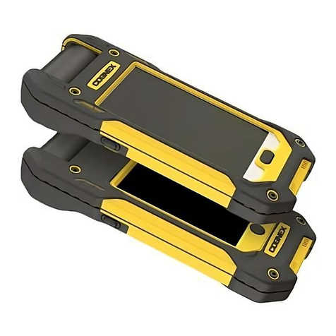

Table of Contents
Legal Notices 2
Table of Contents 3
Symbols 4
Getting Started 5
About MX-1000 5
MX-1000 Accessories 6
MX-1000 Layout 8
Layout of the Charging Station 9
Indicator LEDs 10
Dimensional Drawings 11
MX-1000 Specifications 12
Imager Specifications 12
LED Wavelengths 12
Charging Station Specifications 12
Setting up the MX-1000 13
Assembling the MX-1000 13
Assembling the Reader with the Pistol Grip 15
Charging 16
Charging an MX-1000 Using the Wireless Charging Station 17
USB Type-C Charging 20
Changing Battery in the MX-1000 Reader 20
Changing Battery in the Pistol Grip 22
Reading Codes with your MX-1000 24
Field of View and Reading Distances 24
Cleaning and Maintenance 25
Cleaning the Reader Housing 25
Cleaning the Reader Lens Cover 25
Compliance Statements 26
Compliance Statements: MX-1000 Charging Station 27
中国大陆RoHS (Information for China RoHS Compliance) 28
Precautions 29
3
Table of Contents

Symbols
The following symbols indicate safety precautions and supplemental information:
WARNING:This symbol indicates a hazard that could cause death, serious personal injury or electrical shock.
CAUTION:This symbol indicates a hazard that could result in property damage.
Note: This symbol indicates additional information about a subject.
Tip: This symbol indicates suggestions and shortcuts that might not otherwise be apparent.
4
Symbols

Getting Started
This section provides general information about the Cognex MX-1000 Vision-Enabled Mobile Terminal (henceforth
referred to as "MX-1000 reader"). You can also find information on the MX-1000 accessories and the physical layout of
the reader and the charging station in this section.
About MX-1000
The Cognex MX-1000 reader is a handheld ID mobile device supporting an integrated user interface based on a
consumer mobile device in an industrial grade housing. It features high-speed bar code reading performance in a
modular, rugged design that supports a variety of 3rd party mobile devices. The MX-1000 reader provides the industry’s
most advanced technology for reading 1-D and 2-D codes. The MX-1000 X also reads challenging 2-D DPM codes. It is
designed to withstand heavy use in industrial settings. The unique modular design allows you to stay current with mobile
communications technology and easily replace or upgrade components without the need for a service plan. The
enhanced interface allows you to write and implement your own application according to the needs of your work
environment.
The MX-1000 reader offers the following features:
lWireless charging
lLED aimer and illumination
lNo external connectors
lVibro at the bottom part that ensures adequate feedback even in loud environments
The MX-1000 Kit includes the following:
lMX-1000 reader
lBattery
lWrist strap
Note: A mobile device is necessary to work with the MX-1000 reader. The currently supported devices are:
lGalaxy S6, S7, S8 S9
lGalaxy J3
lGalaxy A3
lGalaxy XCover 4
liPhone SE, 5S, 6, 6S, 7, 8
liPod touch generations 5th and 6th
For more information, see http://www.cognex.com.
5
Getting Started

MX-1000 Accessories
Battery for reader (3120 mAh) DMA-MTBATTERY-01
Battery for pistol grip accessory (3070 mAh) DMA-HHBATTERY-01
Pistol grip
Note: The grip features its own trigger
button and an additional battery which
can be charged via the charging station.
DMA-GRIP-01
Belt holster DMA-HOLSTER-01
DMA-HOLSTER-02
Charging station (inductive) DMA-MTBASE-US
DMA-MTBASE-EU
Charging station (non-inductive) DMA-MTBASEP-US
DMA-MTBASEP-EU
Multi-device charger DMA-MTBASE4-US
DMA-MTBASE4-EU
DMA-MTBASE4BKT-US
DMA-MTBASE4BKT-EU
Multi-battery charger DMA-MBC-US
DMA-MBC-EU
6
Getting Started

Wireless car charger DMA-VMCHARGER-00
Power supply for charging station 24V/24W DMA-24VPWR-US
DMA-24VPWR-EU
USB Type-C battery charger kits:
1. USB Type-C Battery Cover (DMA-
MXUSB-00) + USB Type-C 3Amp Car
Charger (DMA-MXUSB-CHARGER)
2. USB Type-C Battery Cover (DMA-
MXUSB-00) + Handstrap (DMA-
MXSTRAP-00)
3. USB Type-C Battery Cover (DMA-
MXUSB-00) + USB Type-C 3Amp Car
Charger (DMA-MXUSB-CHARGER) +
Handstrap (DMA-MXSTRAP-00)
1. DMA-MXUSB-01
2. DMA-MXUSB-02
3. DMA-MXUSB-03
Passive car holder1DMA-VMHOLDER-00
Top Cover DMA-COVERKIT-S4
DMA-COVERKIT-S5
DMA-COVERKIT-S6
DMA-COVERKIT-S7
DMA-COVERKIT-S8
DMA-COVERKIT-S9
DMA-COVERKIT-J3
DMA-COVERKIT-J327
DMA-COVERKIT-J330
DMA-COVERKIT-A3
DMA-COVERKIT-X4
DMA-COVERKIT-I5
DMA-COVERKIT-I6
1Using or storing the device outside of the recommended temperature ranges may damage or reduce the lifespan of the battery. Leaving the
MX Series Mobile Terminal with a mobile device in direct sunlight for an extended amount of time can raise the temperature above the
recommended limit.
7
Getting Started

MX-1000 Layout
1Scanner head (rotatable by 45°)
2 Indicator LEDs
3 Side trigger buttons
4 Power button
5 Touch screen
6 Home button
7 Speaker vents
8 Recessed area for mobile camera
9 Slider to lock battery cover
10 Battery cover
11 Lanyard hook
12 End cap of pistol grip*
13 Trigger button on the pistol grip*
*Pistol grip is optional
8
Getting Started

Layout of the Charging Station
Top view:
1 Charging station power LEDs
2 Device charger bay
3 Battery charger LED
4 Spare battery charger bay
Bottom view:
1 Cable guide
2 Power plug (24 V, jack)
3Power plug (24 V, terminal block)
Note: Supply power by using only one of the connectors.
9
Getting Started

Indicator LEDs
MX-1000 indicator LEDs
Type Signal Color Interval Meaning
Status Battery health RED and GREEN blinking Battery health low
Configuration GREEN 2 short blinks/1 sec Internal
reconfiguration
Overheat protection RED 2 short blinks/1.5 sec Overheat protection
Status
standalone
Low battery status RED every 4 sec Charged 15-10%
RED every 2 sec Charged 10-8%
RED every 1 sec Charged 8-5%
RED every 0.5 sec Charged < 5%
Status
base station
Charging RED continuous Charging
Charged GREEN continuous Fully charged
Error RED blinking Charging error
Charging station power LEDs
Type Signal Color Interval Meaning
Status Wireless power RED continuous wireless power
disconnected, there is
no device in the
charger bay
GREEN continuous wireless power
connected, charging is
active
Battery charger LEDs
Type Signal Color Interval Meaning
Status No battery inserted N/A N/A Battery disconnected
Battery charging RED continuous Charging is active
Error RED blinking Charging error
Charged GREEN continuous Charged
10
Getting Started

Dimensional Drawings
11
Getting Started

MX-1000 Specifications
Weight 510 g (675 g with pistol grip)
Operating Temperature 0ºC— +40ºC (+32ºF — +104ºF)
Storage Temperature -40ºC — +60ºC (-40ºF — +140ºF)
Charging Temperature 0ºC — +35ºC (+32ºF — +95ºF)
Maximum Humidity < 95% (non-condensing)
Environmental IP65
Codes 1-D: UPC/EAN/JAN, Codabar, Interleaved 2 of 5, Code 39, Code 128, Code 93,
Pharmacode, GS1 DataBar, PDF417, Micro PDF417
2-D: Data Matrix, QR Code, and MicroQR Code, DotCode and postal code
Power Supply Requirements Battery power
Expected operating time for typical
scan batches (400 scan per hour)
with a fully charged battery
12 hours
Imager Specifications
Specification MX-1000 Imager
Image Sensor 1/3 inch CMOS
Image Sensor Properties 6.0 μm square pixels
Image Resolution (Pixels) 752 x 480 global shutter sensor
Lens Type 3 focal position 6.2 mm, M12 lens with IR blocking filter
LED Wavelengths
The following table shows LED types and the related wavelengths:
LED λ [nm]
RED 617
Charging Station Specifications
Weight 380 g
Operating Temperature 0ºC — +40ºC (+32ºF — +104ºF)
Storage Temperature -40ºC — +60ºC (-40ºF — +140ºF)
Maximum Humidity 95% (non-condensing)
Power Supply Requirements 24 V, 24 W maximum LPS or NEC Class 2 power supply
0.5A (inductive) and 1A (non-inductive)
12
Getting Started

Setting up the MX-1000
This section provides information on how to assemble, and how to set up your MX-1000 reader.
Assembling the MX-1000
The first step in preparing your MX-1000 is assembling the components of your MX-1000 Kit. The MX-1000 Kit contains
the following components:
lBase unit
lBattery +cover
lWrist strap
The phone-specific DMA-COVERKIT contains the following components:
lTop cover
lRubber insert
lUSBcable to connect the Base unit to the mobile device
l4 Allen screws(M3) + Allen key
The DMA-GRIP-01 Kit contains the pistol grip and the pistol grip cable.
The following image shows the layering of the main kit components and the place of the mobile device among the
components.
1 Base unit
2 Barcode reader
3 Rubber insert
4 Mobile device
5 Top cover
6 Pistol grip (optional)
13
Setting up the MX-1000

Perform the following steps to assemble the MX-1000 reader:
1. Carefully place the rubber insert on the base unit which is the lower part of the reader.
2. Take the provided USB cable and plug it into the base unit. Then take your phone and put it on the rubber
insert. Connect it to the base unit by the USB cable.
3. Fix the top cover by tightening the provided four Allen screws (recommended torque: 80 Ncm). Additionally, you
can attach the wrist strap to the reader by passing one of the screws through the loop on the wrist strap.
14
Setting up the MX-1000

Assembling the Reader with the Pistol Grip
1 Pistol grip accessory connector in the battery bay
2 Pistol grip accessory cable
3 Cable connector in the pistol grip
If you want to use your reader with a pistol grip, perform the following steps:
1. Open the back cover of the reader by unlocking the sliders and take out the battery.
Note: For more information about back cover locking and opening, see Changing Battery in the MX-1000
Reader).
15
Setting up the MX-1000

2. Plug the pistol grip accessory cable into the grip accessory connector.
WARNING:Do not insert the battery into the pistol grip during the assembly process.
Note: For more information on how to insert the battery into the grip after the assembly process, see
Changing Battery in the Pistol Grip on page22
3. Insert the cable to the cable connector in the battery bay.
4. Insert the reader battery into the battery bay, and assemble the pistol grip and the reader by tightening the four
Allen screws (recommended torque: 65 Ncm).
Charging
16
Setting up the MX-1000

Charging an MX-1000 Using the Wireless Charging Station
You can charge your MX-1000 reader using the wireless charging station. It has threaded inserts at the bottom to be
securely mountable on different surfaces. It allows the charging of both the spare battery and the main unit.
The charging station can charge the main battery, the spare battery, and - if attached - the pistol grip battery at the same
time.
To fully charge the battery using the charging station is:
l4 hours when charging the battery separately
l10-11 hours when charging the phone, and the battery in the device with the pistol grip (with battery)attached
l6 hours when charging the battery in the device and the phone
l6 hours when charging the battery in the pistol grip attached to the device, but the main battery is not inserted
1 Charging main battery and mobile device in the device charger bay
2 Charging spare battery in the spare battery charger bay
When you place your reader containing your mobile phone into the device bay of the charging station, the charging
station power LED becomes green and the indicator LED of the reader becomes red (1). It indicates that the charger is
active and the reader is charging. When the charging process is complete, the indicator of the reader LED turns green
(2).
17
Setting up the MX-1000

1) 2)
When the wireless reader is removed from the device bay, the charging station power led becomes red. It indicates that
the charger is inactive.
To charge the spare battery, you need to insert it to the battery charging bay of the charging station. Make sure that the
battery fits the battery bay properly.
18
Setting up the MX-1000

Once you put the spare battery into the battery bay, the battery charger LED light turns to red, while the flashing red light
indicates an error.
When charging is finished, the LED light turns green.
Note: For more information on the battery charger LED lights, see Indicator LEDs on page10
19
Setting up the MX-1000

USB Type-C Charging
You can also charge your MX-1000 reader using USB if you use a USB Type-C battery cover.
Tip: For optimum charging, do not power off your mobile device during the charging process.
1. Insert a 5V/3A Type-C USB cable into the slot in the battery cover, and the reader starts charging.
Note: Both the cable and the power supply must be compatible with 5V/3A.
Changing Battery in the MX-1000 Reader
The MX-1000 reader contains a battery (lithium polymer battery, capacity: 3000 mAh) which you can charge by putting it
into the spare battery charging bay of the charging station.
To change the battery:
1. Open the battery cover of your reader by unlocking the two cover sliders and pulling the cover side.
2. Take out the battery and charge it using the charging station.
20
Setting up the MX-1000
Other manuals for MX-1000
5
Table of contents
Other Cognex Handheld manuals

Cognex
Cognex MX-1000 User manual

Cognex
Cognex DataMan 8072 User manual

Cognex
Cognex MX1100X-IOS User manual

Cognex
Cognex MX-1100 User manual

Cognex
Cognex MX-1000 User manual

Cognex
Cognex MX-1502 User manual

Cognex
Cognex MX-1100 User manual

Cognex
Cognex MX-1100 User manual

Cognex
Cognex MX-1500 User manual

Cognex
Cognex MX-1502 User manual