Cohu HD Helios Products 3120 HD Series User manual

HeliosTM Products
INSTALLATION MANUAL 3120HD Series
Dome Positioner System
July 15, 2014
Technical Manual 6X-1109E www.CohuHD.com

2 6X-1109E
Table of Contents
About this document 3
Additional information and documents related to the camera system 3
FCC compliance 3
Returns 4
Shipment 4
Safety instructions 4
1.0 Introduction 6
1.1 Product Description 6
1.2 Optional Accessories 7
2.0 Installation 8
2.1 Power over Ethernet 9
2.2 System Cable Requirements 10
2.3 18-pin MS Connector and Its Mating System Cable Connector 11
2.4 Alarm Input/Output 11
2.5 CohuHD-Manufactured System Cables (CA275 Series) 12
3.0 Mounting Methods 13
3.1 Wall Mount. CohuHD p/n 7411420-001 13
3.2 Pole Mount. CohuHD p/n 8518-2 14
3.3 Installation Procedures 15
4.0 Quick Check 18
4.1 Computer Requirements 18
4.2 IP Control and Viewing of Camera 18
4.3 Factory Default IPAddress and Settings 18
4.4 Factory Default User Names and Passwords 18
4.5 Assigning the New Camera IPAddress 19
4.6 Using the CohuONVIFDiscovery Software to Discover the Camera 20
4.7 Checkout Procedure 21
5.0 Maintenance 22
5.1 Camera Housing Pressurization 22
5.1.1 Schrader Valve 23
5.1.2 Pressure Relief Valve 23
6.0 Warranty 24

6X-1109E 3
About this document
This manual contains information on the installation and maintenance of the CohuHDTM HeliosTM 3120HD
Series Camera System. Please read this manual carefully prior to installation to prevent any accidental
damage or misuse. The manual is available from the CohuHD website at:
http://www.CohuHD.com/Files/install_manuals/3120HD_IM.pdf
The information in this manual is subject to change without notice. Please refer to the above website for
the latest information.
NOTE: All graphics contained within this document, including screenshots and other displays, are for reference use
only and are subject to change.
Additional information and documents related to the camera system
For information on the camera system operation and conguration, please see Operation manual 6X-1090.
The manual is available from the CohuHD website at:
http://www.CohuHD.com/Files/operation_manual/HeliosOperationManual.pdf
Copyright/Intellectual Property Rights statement
Copyright 2014 by CohuHD Costar, LLC. CohuHD Costar, LLC has intellectual property rights to technology
embodied in the product described in this manual.
CohuHD™ and Helios™ are trademarks of CohuHD Costar, LLC.
FCC compliance
This equipment has been tested and found to comply with the limits for a Class A digital device pursuant
to Part 15 of the FCC Rules. These limits are designed to provide reasonable protection against harmful
interference when the equipment is operated in a commercial environment. This equipment generates,
uses, and can radiate radio frequency energy, and, if not installed and used in accordance with the instruc-
tion manual, may cause harmful interference to radio communications. Operation of this equipment in
a residential area is likely to cause harmful interference, in which case the user will be required to correct
the interference at his own expense.
This device complies with Part 15 of the FCC Rules. Operation is subject to the following two conditions:
(1) this device may not cause harmful interference, and (2) this device must accept any interference
received, including interference that may cause undesired operation. Changes or modications to this
device void the warranty.

4 6X-1109E
Returns
This item was thoroughly tested and carefully packed at the factory prior to shipping. Upon acceptance by
the carrier, the carrier assumes responsibility for the item’s safe arrival. If you receive the item in a damaged
condition, apparent or concealed, a claim for damage must be made to the carrier.
If a visual inspection shows damage upon receipt of this shipment, it must be noted on the freight bill or
express receipt and the notation signed by the carrier’s agent. Failure to do this can result in the carrier
refusing to honor the claim.
When the damage is not apparent until the unit is unpacked, a claim for concealed damage must be made.
Make a mail or phone request to the carrier for inspection immediately upon discovery of the concealed
damage. Keep all cartons and packing materials.
To return the product to the factory for service, please contact the Customer Service Department for a Return
Material Authorization (RMA) Number.
Prominently display the RMA number on the outside of the shipping container(s) and on paperwork
contained inside. Give a brief description of why the equipment is being returned and list the symptoms of
any problems being experienced with the equipment.
Shipment
Safety instructions
IMPORTANT
If the camera needs to be shipped, please use the original packaging material which was designed to
protect the product during transportation. If the original packaging is lost or damaged, please order a
replacement from Customer Service.
WARNING
PoE (Power over Ethernet) injectors used with this camera system may operate from 90-240 Vac. These
voltages are dangerous. Use extreme care working with equipment connected to these voltages.
WARNING
Voltages that present a shock hazard may exist on PoE circuits. Use caution to avoid direct contact with
exposed, bare Ethernet circuit conductors or connector contacts.
WARNING
Do not remove camera from housing. There are no user serviceable parts inside.
CAUTION
In order to avoid deterioration of the color lter of the CCD and potential discoloration of the image
avoid pointing the camera directly toward the sun or other bright source.

6X-1109E 5
Pressurized camera
This environmentally sealed camera housing is pressurized with dry nitrogen to prevent moisture from af-
fecting the optics or electronics. The nominal internal pressure is 3.5 psi (24.1 kPa).
• Installation must be done by qualied installers, and conform to all local codes.
• It is the user’s responsibility to ensure that the mounting methods are safe and adequate for the
location.
• Use only stainless steel hardware to fasten the mount to an outdoor surface.
• To prevent damage from water leakage when installing a mount outdoors, apply sealant around the
bolt holes between the mount and mounting surface.
• All servicing must be performed by qualied service personnel. The unit contains sensitive
devices that can be damaged by static discharge. To reduce the risk of damage to the unit by static
discharge do not perform any servicing other than described in these instructions. If the unit is
defective, please contact the Customer Service Department for technical assistance.
• It is the sole responsibility of the installer to provide proper installation in compliance with all local
codes and regulations.
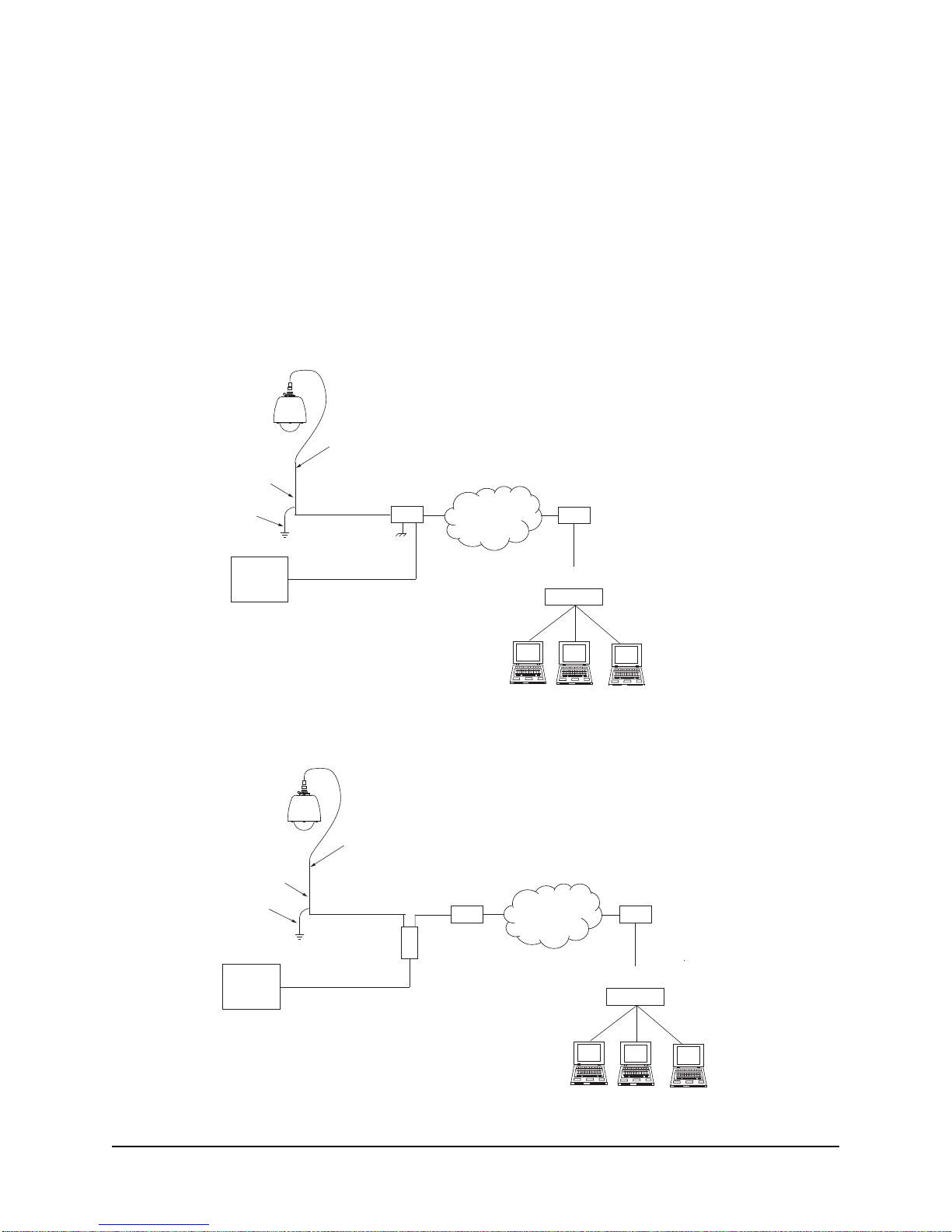
• To provide protection against electrical surges induced by lightning, static charges, or any other
cause, the camera and cabling system must be properly grounded to earth. For installation on
a building, the camera must be bonded (that is, provided with a low impedance connection) to the
building’s structural earth ground system. For installation on a metal pole with a proper ground
system at the base, the camera must be bonded to the pole. For installation on a non-grounded or
insulated support, the camera must be grounded with an adequate ground strap or wire between
the camera and a nearby ground system, or to a ground system installed at the base of the support.
Failure to adequately ground the camera may lead to failure of the camera. This applies to low
voltage (i.e. PoE cameras) as well as to 115 Vac cameras. Failures due to surges are not
covered by the warranty, as they are not due to defects in material or workmanship, and it is
the installer’s responsibility to meet these grounding requirements.
IMPORTANT
Do not remove the clear plastic tube that protects the pressure relief valve poppet, or the pressuriza-
tion could be lost. The pressure relief valve is designed to open when the internal pressure exceeds
5 psi (34.5 kPa). Environmental factors such as high temperature or high altitude (including during air
transport) can cause the relief valve to open and bleed off excess pressure, resulting in lower pressure
at normal environmental conditions. See Section 5.1 of this manual for more information on maintaining
the camera housing pressurization.
IMPORTANT
the packing foam material is selected to provide appropriate shock absorption in shipment,
and that the same material must be used if the camera needs to be shipped (whether on RMA
back to us, or to anywhere else for deployment).
CAUTION
Prolonged exposure to temperatures below -25°C (-13°F) without power applied to the camera is to be
avoided. It will affect operation of the lens and/or motion functions, and can result in damage.
A warm-up time of 90 minutes is required before full operation can be commenced. A reset of the cam-
era module is required after the warm-up period and prior to operating the camera.

6 6X-1109E
1.0 Introduction
The CohuHD 3120HD Camera System is an IP camera system in an IP67
protected pressurized dome positioner. The camera system provides IP video
streamswithH.264andMJPEGcompression.Thecameraprovidescontinuous
360 degree pan (azimuth) motion range with 95 degrees of tilt motion range.
Control interfaces are via Ethernet network connection.
For more information on specications and datasheets, please refer to the
CohuHD website.
1.1 Product Description
Camera Top
NOTE: See Section 3.3 for instructions on the Quick Disconnect disassembling/reassembling.
18 Pin Connector
1.5 NPT Nipple
Safety Strap
Sun Shield
Ventilation Hole
(6)
Pressure Relief Valve (5 psi)
Shown with Plastic Tubing
Quick Disconnect
Bottom
Schrader Valve
Shown with Installed Cap
Lock Down Bolts (2)
Quick Disconnect
Top
NPT - National Pipe Thread

6X-1109E 7
1.2 Optional Accessories
The following optional mounts, cables, and eld connectors (or eld connector kits) are recommended by
CohuHD for camera system installation, and can be purchased with the camera system.
Mounts:
• Wall: CohuHD p/n 7411420-001
• Pole Mount Kit: CohuHD p/n 8518-2
The kit includes:
Wall mount: CohuHD p/n 7411420-001
Pole mount adapter: CohuHD p/n 7411421-001
For more information on each type of mount see Chapter 3 of this manual.
Cables:
• CA275 Series. CohuHD p/n 7411275
For more information on cables see Section 2.4 of this manual.
PoE Injector:
• PoE Injector: CohuHD p/n 7411539-001
For more information on the injector see Section 2.1 of this manual.
Field Connector:
• Mating Connector: CohuHD p/n 1310230-211 (supplied, if ordered)
For more information on the connector see Section 2.3 of this manual.
Transformer:
• 24 Vac Transformer: CohuHD p/n 7411543-010 (supplied, if ordered)
For more information on the connector see Section 2.3 of this manual.
Pole Mount Adapter
Wall Mount

8 6X-1109E
2.0 Installation
This chapter covers the general installation and cable requirements of the 3120HD series.
Before starting installation:
• Choose the installation mounting method. See Chapter 3 of this manual.
• Have the system cable available. CohuHD-manufactured cables can be purchased with the camera
system. See Section 2.4.
• Verify that the cables can be routed to the location of the mounting assembly.
See Chapter 3 for details on the installation procedure for recommended mounts.
Figures 1, 2 and 3 show interconnection diagrams for the 3120HD series cameras:
• Figure 1 shows a setup for the camera system using IP output and 24 Vac power.
• Figure 2 shows a setup for the camera system with PoE-enabled switch.
• Figure 3 shows a setup for the camera system using the PoE injector with non-PoE switch.
These diagrams represent typical installations. Each installation site will have its own unique requirements.
Network
Switch
Router/Switch
CAT5e
Cable Router/Switch
WAN
LAN
System Cable
Default IPAddress
192.168.2.150
Earth
Ground
Cable Shield(s)
Power
24 Vac ± 10%
@ 3 A min
Properly secure the camera system
before the power is applied.
Figure 1. Interconnection Diagram, 24 Vac

6X-1109E 9
2.1 Power over Ethernet
The 3120HD camera system is compliant with the IEEE 802.3at standard. Power to the camera is supplied
through the network cable. Two types of PoE implementations are specied by the standard:
• Endspan PoE: Power is applied directly by the switch to the camera. This method requires the
deployment of a PoE-enabled switch.
• Midspan PoE: Power is supplied by an injector placed between an existing non-PoE switch and
the camera.
PoE injectors can be ordered from CohuHD. Please refer to the CohuHD website in the 3120HD series
specications section for ordering information. The PoE injector selected for use with 3120HD must meet
the following requirement:
• Be compatible with the IEEE 802.3at standard. Please refer to the following website for more in-
formation: http://en.wikipedia.org/wiki/Power_over_Ethernet.
Network
Switch
Router/Switch
WAN
Router/PoE Switch
LAN
CAT5e
Cable
System Cable
Default IPAddress
192.168.2.150
Earth
Ground
Cable Shield(s)
Properly secure the camera system
before the power is applied.
Power
Figure 2. Interconnection Diagram with PoE-enabled switch
Network
Switch
Power
Router/Switch
Router/
non-PoE Switch
PoE Injector
WAN
LAN
In
Out
CAT5e
Cable
System Cable
Default IPAddress
192.168.2.150
Earth
Ground
Cable Shield(s)
Properly secure the camera system
before the power is applied.
Figure 3. Interconnection Diagram with non-PoE Switch

10 6X-1109E
2.2 System Cable Requirements
To build the camera system cable, CohuHD recommends:
• For Ethernet/PoE: CAT5e or better cable. For distances up to 100 meters (328 feet), use CAT5e
cable with four pairs of copper wire, 24 AWG.
NOTE: The maximum recommended cable length for Ethernet is 100 m (328’). However, other factors
may reduce the distance Ethernet can be successfully used, such as EMI from other sources.
• When wiring to the Ethernet pins, consider if they are to be wired for the NIC (Network Interface
Card) in a PC or for system connections to a hub, switch, router, or similar device. See Tables 1
and 2.
• All Ethernet wiring must be done in accordance with TIA/EIA568-C standards.
• Wiring to the PoE pins is the same for the NIC in a PC as for system connections to a hub, switch,
router, or similar device.
• For Power: Three wires, insulated for 300 V minimum, 18 AWG cord for power. Use for distances
up to 80 feet (29 m) for 24 Vac cables.
• For Alarm I/O: Four wires, insulated for 300 V minimum, 24 AWG. Use for distances up to 250 feet
(76.2 m).
• All system cables must be shielded, and the shield must be bonded to earth ground.
Table 1. Ethernet Cable Wiring to a Hub, Switch, or Router (Straight Wiring)
Ethernet
Function Camera Connector
Ethernet Pins Corresponding
RJ-45 Ethernet Pins
TX+ D 3
TX- E 6
RX+ F 1
RX- H 2
This Ethernet wiring is intended to connect a camera to the NIC card in a
PC. Note: For clarity, only signal lines are shown.
Table 2. Ethernet Cable Wiring to a PC (Crossover Wiring)
Ethernet
Function Camera Connector
Ethernet Pins Corresponding
RJ-45 Ethernet Pins
TX+ D 1
TX- E 2
RX+ F 3
RX- H 6
This Ethernet wiring is intended to connect directly to a hub, switch, or
router. For connection directly to a PC it will be necessary to use either
a crossover cable or a crossover adapter. See Table 2. Note: For clarity,
only signal lines are shown.

6X-1109E 11
2.3 18-pin MS Connector and Its Mating System Cable Connector
All system electrical connections for the 3120HD seriesroute through an 18-pin MS-type metal connector
installed in the dome housing. Table 3 lists pin functions of the camera connector, which are identical to the
corresponding pin functions of the mating connector.
Camera connector:
• Amphenol p/n PT07C-14-18PW(027) or equivalent, CohuHD p/n 1310225-211.
Mating connector:
• Amphenol p/n PT06E-14-18SW(476) or equivalent, CohuHD p/n 1310230-211 (supplied, if ordered).
2.4 Alarm Input/Output
Two alarm inputs and two alarm outputs are available to interface with the 3120HD Event software.
Alarm Inputs
Pins J and M on the MS connector connect to Alarm 1 In and Alarm 2 In, respectively. A contact closure
between the alarm input and the Alarm Common (MS connector pin G) will generate an alarm event.
CAUTION: Do not connect a power source to the alarm inputs.
Alarm Outputs
Pins N and P on the MS connector connect to Alarm 1 Out and Alarm 2 Out, respectively. When an alarm
out event is generated by the 3120HD event software, a relay contact connects the alarm output to the Alarm
Common (MS connector pin G).
CAUTION: The alarm output maximum voltage is 50 Vac, maximum current is 250 mA.
NOTE: CohuHD cable CA275A has only Alarm 1 Out. Use CA275B if both Alarm 1 out and Alarm 2 Out is
required. See Section 2.5.
Pin Location Diagram
MS-type Connector
View from the front (mating) side
Table 3. MS Connector Pinouts
MS Connector
Pin Function
F Ethernet RX+
H Ethernet RX-
DEthernet TX+
EEthernet TX-
B Ethernet PoE Vdc+
C Ethernet PoE Vdc+
T Ethernet PoE Vdc-
K Ethernet PoE Vdc-
R24 Vac Low
S 24 Vac High
U Earth Ground
N Alarm 1 Out
P Alarm 2 Out
J Alarm 1 In
M Alarm 2 In
G Alarm Common/
Ground
NOTE: See also Tables 1 and 2

12 6X-1109E
2.5 CohuHD-Manufactured System Cables (CA275 Series)
CohuHD-manufactured cables are available for 3120HD series camera systems operating from PoE or
24 Vac, with MS connector.
Operating Power PoE:
• CA275A, CA275C and CA275D Series
Operating Power 24 Vac:
• CA275B Series
Cables are made with stripped (prepared) leads and connectors. “Stripped” indicates that the wire leads are
stripped and pre-tinned with solder for attachment to a terminal strip or similar device.
CA275A, CA275C and CA275D cables: Maximum cable length for camera systems with operating power
PoE is 328 feet (100 meters). This length limitation is due to Ethernet signal degradation which increases
with cable length. The CA275A, CA275C and CA275D cables are built using a single cable. See cable
drawings.
The CA275B cable: Maximum cable length for camera systems with operating power 24 Vac is 80 feet (29
meters). The length limitation is due to voltage drop in the wires. Minimum cable length is 3 feet (0.9 meters).
The CA275B cable is built using two separate cables. See cable drawings.
Use an Ethernet extender to extend an Ethernet cable beyond its inherent distance limitation. CohuHD
recommends Enable-IT 860 LRE Kit, which can be purchased with the camera system.
Please refer to the CohuHD website for cable drawings:
• http://www.CohuHD.com/Files/datasheet/CA275.pdf
For ordering information please contact your sales representative.

6X-1109E 13
3.0 Mounting Methods
The dome camera system is designed for indoor/outdoor installation. The following mounts are recom-
mended by CohuHD for 3120HD series installation and can be purchased with the camera.
3.1 Wall Mount. CohuHD p/n 7411420-001
Installation to a Wall
Wall Mount. Dimensions in inches (mm)
18.00 (457.2)
6.50
(165.1)
4.50
(114.3)
6.00
(152.4)
8.00
(203.2)
.75
(19.0) 0.31 (9.5)
THRU (4X)
.75
(1.90)
2.50
(63.5)
1.75
(44.5)
Quick Disconnect
top screws directly
into mount
Secure with four 5/16-inch fasteners
(not supplied) suitable for the
mounting surface
1.5-inch NPT pipe
Set Screw
End Cap

14 6X-1109E
3.2 Pole Mount. CohuHD p/n 8518-2
The pole mount adapter is designed for use with the wall mount (see Section 3.1 for a wall mount) .
12.77
(324.4)
4.50
(114.3)
6.50
(165.0)
Ø3.00 (76.2)
THRU, 2X
2.46
(62.4)
7.00
(177.8)
2.75
(69.8)
Pole Mount Adapter. Dimensions in inches (mm)
Installation to a Pole
Quick Disconnect
top screws directly
into mount
1.5-inch NPT pipe
Three stainless steel
straps are supplied.
Straps fit 3-inch (7.62 cm)
to 8-inch (20.32 cm)
diameter pole
Four 5/16-inch mounting
studs (nuts and split lock
washers supplied) for
attaching the wall mount
Set Screw
End Cap

6X-1109E 15
3.3 Installation Procedures
The 3120HD seriesis designed for outdoor installation.
For installation:
• Use stainless steel (SS) hardware to fasten the camera system to the mounting bracket and mount-
ing brackets to surfaces.
• Use anti-seize compound in order to prevent galling on the threads. CohuHD recommends Never
Seez® from Bostick.
• Use gasket materials, if needed.
• Use a sealant wrap on the camera system waterproof connectors and their mating system cable
plugs for additional protection against moisture in severe conditions. Coax-Seal® is the recom-
mended product.
• Mounts, poles, and metallic conduits must be bonded to earth ground.
Provisions must be made for routing the system cable up to the camera location:
• Pole mounting: if the cable routes up through the pole, support the cable inside the pole to strain
relieve the camera connector.
The sequence of installation can vary from site to site:
• Verify that the system cable can be routed to the location of the mounting assembly.
• For mounting on:
• A wall: Use the mount as a template. Mark and drill holes in the mounting surface. Drill
a hole for the cable if required.
• A pole: Position the pole mount adapter on the pole and secure with the stainless steel
mounting straps (supplied). Use a at blade screw driver or 5/16-inch socket (not supplied)
to tighten strap screws.
• Remove the end cap on the wall mount and route the system cable down into the arm. Reinstall
the end cap.
• For mounting on:
• A wall: Position the wall mount over the mounting holes. Secure with four 5/16-inch
fasteners (not supplied).
• A pole: Attach the wall mount to the studs on the pole mount adapter and secure with the
5/16-inch nuts and washers (supplied).
NOTE: If you install outdoors, seal the fastener holes with an appropriate sealant to prevent
water damage. Apply the sealant between the mount and the mounting surface.
• Install the dome. (Instructions on the Quick Disconnect disassembling/reassembling.)
See Figure 4.
• Remove the safety strap from the top half of the Quick Disconnect (the half with the
threaded nipple attached). Use 3/32-inch hex key.
WARNING:
It is the user’s responsibility to ensure that the mounting methods are safe and adequate for the location.

16 6X-1109E
• Loosen two lock bolts on the Quick Disconnect with a 5/16-inch socket approximately
1/4-inch. Do not remove lock bolts. Separate the two parts of the Quick Disconnect by
rotating approximately 1/16-inch turn CCW.
• Apply anti-seize compound on Quick Disconnect nipple threads.
• Thread the Quick Disconnect nipple into the mounting arm and tighten with a strap wrench
(not supplied).
• Tighten the set screw on the mounting arm securely.
• Route the system cable down through the nipple and attach the system cable plug to the
dome connector.
• Orient the dome properly and attach it to the other half of the Quick Disconnect mounted
to the arm by engaging the pins and rotating approximately 1/16-inch turn CW. Ensure
that safety strap bolts are aligned after rotation. See picture below.
• Snug lock bolts to lock the top and bottom of the Quick Disconnect together. Do not over-
tighten.
• Reattach the safety strap.
NOTE: The top part of the Quick Disconnect is intended to remain in place after installation. If
you need to remove the camera, reverse the above process.
Figure 4. Quick Disconnect Assembly
Safety strap bolts
must be aligned
18 Pin Connector Safety
Strap
Lock Bolt
(2)
1.5 NPT Nipple
1.5-inch NPT pipe
Set Screw
Quick Disconnect Top
Quick Disconnect Bottom
Safety Strap

6X-1109E 17
Overall Dimensions in inches (mm)
NPT - National Pipe Thread
8.34
(211.83)
10.42
(264.66)
ø11.05
(280.67)
ø7.00
(177.8)
ø3.00 (76.20)
3.32 (84.32)
ø1.77 (44.95)
1.5 NPT

18 6X-1109E
4.0 Quick Check
NOTE: All graphics contained within this document, including screenshots and other displays, are for reference use
only and are subject to change.
In order to test the camera system you need the following items:
• Laptop or desktop computer (for computer requirements see Section 4.1)
• 100/1000BASE-T network card installed in your computer
• Microsoft Internet Explorer, version 8 or 9
• 100/1000BASE-T network switch
• CAT5e cable
4.1 Computer Requirements
• Operating System: Windows XP Service Pack 3 (SP3) or newer
• CPU: Intel i7-860S 2.53 GHz or better
• Memory: 4GB DDR3@1066MHz or better
• Hard Drive: 7200 rpm - minimum speed
• Video Card: NVIDIA® GeForce® 9800 GTX+ with 512 MB RAM or better, or high-end ATI
Radeon™ HD series
• Monitor: LCD monitor with 1920 x 1080 or better resolution
• Web Browser: Microsoft Internet Explorer, version 8 or 9
4.2 IP Control and Viewing of Camera
Installation and testing of the camera system can be performed with the built-in Helios Web Interface
application. The Helios Web Interface is designed to work with Internet Explorer (IE) 8 or 9. To view video
properly in the web interface the signed ActiveX control must be installed in the 32-bit Microsoft® Internet
Explorer® (IE) 8 or 9. If ActiveX is not already installed on your computer, you will be prompted to install it
the rst time you access the camera system.
• Allowthecamerasystemtoinstall SignedActiveX®controlbeforeconnectingtothecamera system.
4.3 Factory Default IP Address and Settings
The camera is shipped with:
• IPAddress: 192.168.2.150
• Subnet mask: 255.255.0.0
• Gateway: 192.168.2.1
4.4 Factory Default User Names and Passwords
• Admin: Camera, case-sensitive
• Priv: No password
• User: No password
• Guest: No password

6X-1109E 19
4.5 Assigning the New Camera IP Address
No two devices on a single Ethernet network can have the same IP address. Use the following steps to
change a camera IP address before a second camera is added to the subnet.
• Set your computer IP address to the same subnet as the camera IP address.
IMPORTANT: In order to make changes in camera conguration the user must be logged in as Administrator.
• Change the camera address. The camera address can be changed manually or through a Dynamic
Host Conguration Protocol (DHCP) server. See Operation Manual 6X-1090.
• Click the camera Setup button.
• Click the Conguration button.
• Click the Communication tab.
The Communications tab is used for performing network conguration of the camera. Changes to this tab can
only be made by the Admin account. Care must be taken when modifying parameters on this page as the
changes can make the camera inaccessible through the network. Consult with your network administrator
before starting to assign new network settings to ensure that your camera won’t conict with other devices.
• Write down the new camera address to make the camera easy to nd later. If the camera IP address
becomes lost, use the CohuONVIFDiscovery software to nd the camera on a network. The software
is available as a free download at http://www.CohuHD.com/content/downloads. Under Software &
Protocol Downloads > Setup Test Applications > Helios and 7500 Camera Series Discovery Tool
click “download now”. See Section 4.6.

4.6 Using the CohuONVIFDiscovery Software to Discover the Camera
• Download the software. See Section 4.5. Run the CohuONVIFDiscovery.exe le. Click to start it.
• The CohuONVIFDiscovery window will be displayed.
NOTE:Autodiscoveryfeatureusesnetworkmulticastpacketsandmaynotworkthroughnetworkrouters.
• Click on the “Start Discovery” button. A list of cameras will be automatically displayed.
NOTE: Use the MAC Address or Model Index to identify CohuHD cameras. “00-09-f2” identies cameras
as CohuHD cameras. The MAC address of the camera is on the serial number label.
• Right click a camera entry. Click Copy IP to Clipboard.
NOTE: The CohuONVIFDiscovery software uses the ONVIF device discovery service. If the ONVIF discov-
ery service is disabled, the CohuONVIFDiscovery software will not nd the camera.
20 6X-1109E
Table of contents
Other Cohu HD Security Camera manuals