COHU 3940 IP i-Dome User manual

6X-1070D 1
INSTALLATION
3940 IP i-Dome
Installation Manual
COHU, INC. ELECTRONICS DIVISION
3940 IP iDome
CAMERA/POSITIONER SYSTEM
Figure 1. Model 394x-590x
Ethernet iDome
FCC
CE
www.cohu-cameras.com
June 28, 2012
Technical Manual 6X-1070D
www.cohu-cameras.com/content/contactus

6X-1070D
2
INSTALLATION 3940 IP iDome
Refer to table 9 at the rear of this
manual for camera specications
Camera Software Support
Controlling this camera and viewing its video requires
software running on a PC. Currently, two options are
available:
1. For operation of the camera during installation and
setup, download WinMPC.Net from the Cohu website. This
software both controls the camera and views its video.
2. For the day-to-day operating software download the
SDK (Software Development Kit) from the Cohu website. A
programmer will then use this SDK to write the operating
software for the camera.
A third software download is available to update
rmware in the camera. This download will include DOS
upload /burn software and the actual rmware updates
themselves.
cohu-cameras.com
FCC, 15B, Class A Ac Power Line Conducted Emissions
FCC, 15B, Class A Radiated Radiofrequency Emissions
EN 55022, Class A Power Line Coducted Emissions
EN 61000-6-3, Class A Signal Control dc Input/dc Output
Conducted Emissions
EN 55022, Class A Radiated Radiofrequency Emissions
IEC 61000-4-2, A1 + A2 Electrostatic Discharge Immunity
IEC 61000-4-3 Radiated RF Field Immunity
IEC 61000-4-4 EFT / Burst Immunity
IEC 61000-4-5 Lightning Surge Immunity
IEC 61000-4-6 RF Common Mode Immunity
EMI/EMC TESTS COMPLETED
NOTE: This equipment has been tested and found to comply with
the limits for a Class A Digital Device, pursuant to Part 15 of the
FCC Rules. These limits are designed to provide reasonable
protection against harmful interference when the equipment is
operated in a commercial environment. This equipment gener-
ates, uses, and can radiate radio frequency energy and, if not
installed and used in accordance with the instruction manual, may
cause harmful interference to radio communications. Operation
of this equipment in a residential area is likely to cause harmful
interference in which case the user will be required to correct the
interference at his own expense.
This device complies with part 15 of
the FCC Rules. Operation is subject
to the following two conditions: (1) this
device may not cause harmful interfer-
ence, and (2) this device must accept
any interference received, including
interference that may cause undesired
operation.
Changes or modications to this equip-
ment not expressly approved by Cohu
Electronics could void the users author-
ity to operate the equipment.
FCC STATEMENTS

6X-1070D 3
INSTALLATION
3940 IP i-Dome
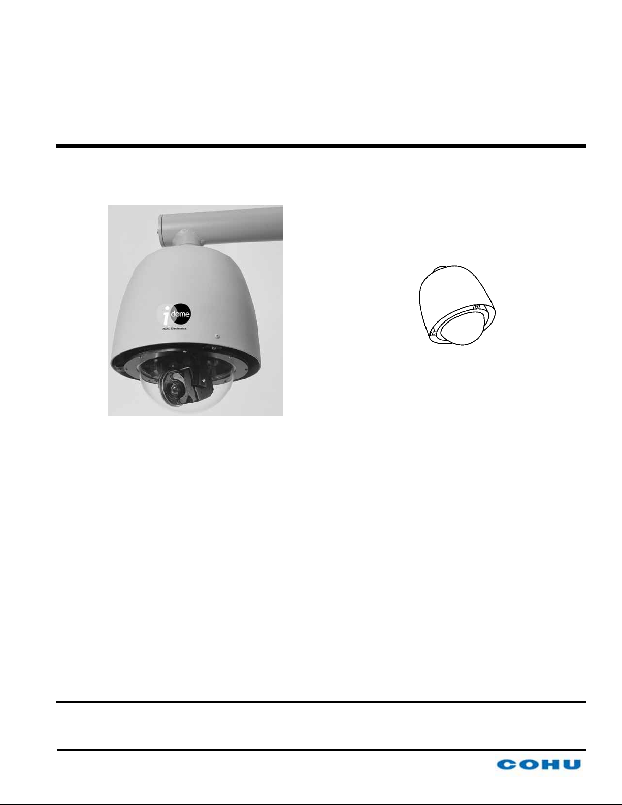
1.0 GENERAL DESCRIPTION
The 3940 IP iDome is an integrated camera/posi-
tioner unit that combines a high performance digital
signal processing camera, pan-and-tilt, and control
receiver for communications into one integrated
package (gure 1). A 35x lens is provided.
It communicates with Ethernet TDP packets and
supplies video via Ethernet UDP packets.
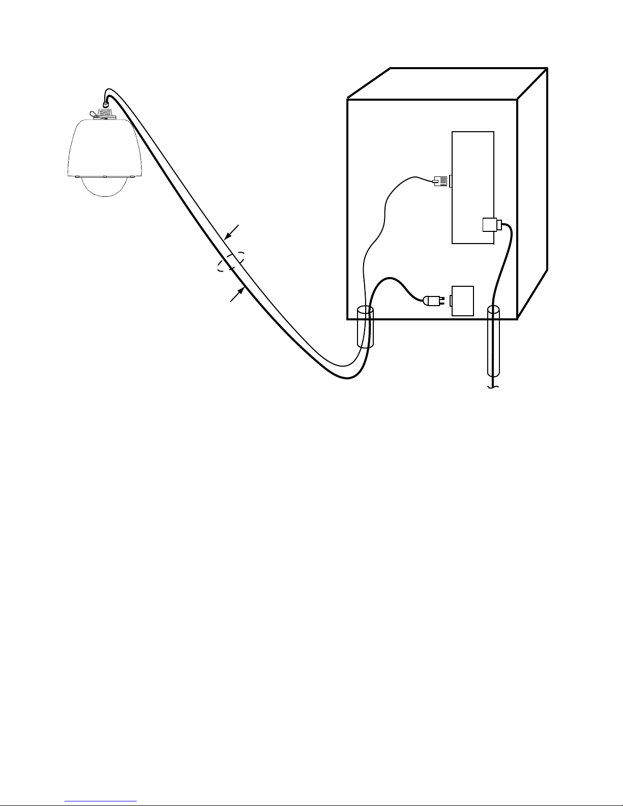
An IP dome is congured to connect to a hub,
switch, or router. Connecting it directly to the NIC
(Network Interface Card) in a computer will require
use of a crossover cable or crossover adapter.
Throughout this manual the entire assembly will
typically be referred to as the “iDome” or just the
“Dome.”
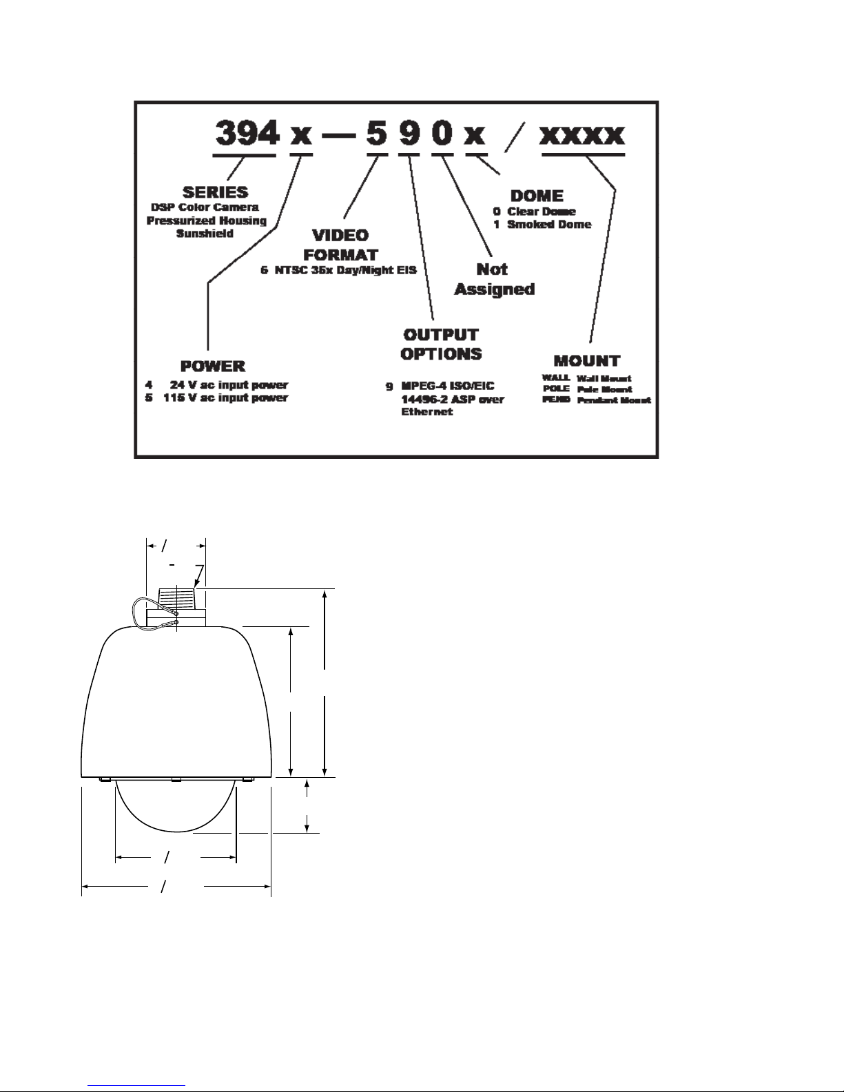
Specications are contained in table 9 at the
back of this manual. A model number interpretation
diagram is provided in gure 2. This diagram can be
used to interpret an existing model number.
1.1 ELECTRICAL CHARACTERISTICS
The camera uses digital signal processing. It has
an internal source ID generator. Integration control
plus a built-in video storage card provides full color
continuous video even at very low light levels.
The iDome speeds are variable with maximums
of 250° per second for pan and tilt. Pan range is a
continuous 360 degrees while the tilt range is 0 to 90
degrees from the horizontal with auto-ip at the 90°
point. There are 64 preset positions with a preset ac-
curacy of 0.1 degree. When responding to standard
pan-preset or manual control, the iDome can move
with a pan speed of 250° per second.
This iDome will operate in temperature ranges
from -34° to +50° C and with winds of up to 90 mph.
The enclosure protects against salt, grime, dirt, and
moisture.
The integrated receiver/driver, contained within
the iDome, communicates using Cohu protocol
messages. These messages control camera DSP
functions and also the pan, tilt, zoom functions of
the positioner. All iDome functions are operable via
Ethernet serial communications.
Up to 64 pre selected scene locations can
stored for later access These Preset locations
are available for use with the Tour functions. All 64
preset positions are stored in nonvolatile memory
to preserve them in the event of a power failure.
Each iDome “address” within a surveillance
system can be selected electronically from the
Monitoring Center. There are no mechanical dip
switches to set at the camera, and each unit re-
sponds to the central command only if addressed.
This provides greater integration exibility for the
designer and more dynamic camera control for the
operator.
Privacy zones can be set up using polygon
shaped windows drawn with the Viewer/GUI soft-
ware. These blanking windows are generated elec-
tronically within the digital signal processing (DSP)
and provide positive control of such areas.
Electronic image stabilization (EIS) is a stan-
dard feature for the camera module used in this
dome. This EIS feature can be set to either 5 or 16
hertz to minimize the effects of slight vibrations on
a Dome in certain mounting situations — such as
when it is mounted on a tall pole.
1.2 SOFTWARE DOWNLOADS
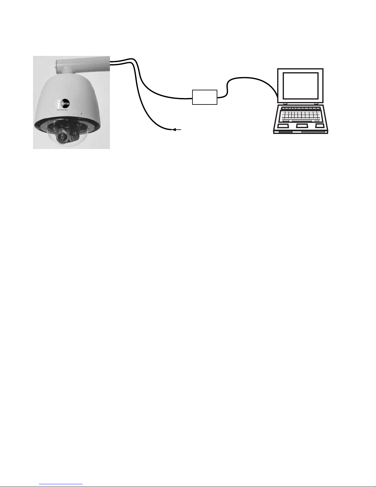
This camera is intended for computer control
and that computer must be running control and
viewing software dedicated to this camera.
Two software packages related to operating the
camera are available for download from the cohu-
cameras.com website. A third package is available
to update the camera rmware. These downloads
are:
1. WinMPC.Net
2. Software Development Kit (SDK)
3. Firmware Updates
These packages are described below. Section
1.2.4 gives a brief functional description of the
camera in relation to this software requirement.

6X-1070D
4
INSTALLATION 3940 IP iDome
1.2.1 WinMPC.Net Installation and Setup
Software
For installation and setup of a camera use Cohu
WinMPC.Net software. This software is not intended
for the day-to-day operation of the camera. It is in-
tended to control a single camera during installation
and maintenance operations.
1.2.2 Software Development Kit (SDK)
A software development kit is available for those
desiring to write their own software to control the
iDome and to view video from the camera. This soft-
ware can be downloaded from the cohu-cameras.
com website.
1.2.3 Firmware Update Software
Any available rmware updates available for this
camera can be downloaded from the cohu-cameras.
com website. This download will consist of three
parts:
Figure 2. Model Number Interpretation Diagram
11
2NPT
8.34
10.42
O11.05
Unless otherwise noted, all dimensions in inches
NPT is National Pipe Thread
O6.99
3.32
O3.00
Figure 3. iDome Dimensions

6X-1070D 5
INSTALLATION
3940 IP i-Dome
Figure 4. Basic Mounting
Congurations
PENDANT MOUNT
WALL MOUNT
POLE MOUNT
1. A DOS upload/burn program
2. Firmware for a 8051 microcontroller
3. Firmware for a DM642 digital media pro-
cessor.
1.2.4 Functional Description
Video generated by the camera is reduced in
bandwidth using MPEG-4 compression. This com-
pressed video is then sent via Ethernet packets on
CAT-5 cable to the PC. Control commands to the
camera and responses back use Ethernet communi-
cations over the same cable.
At the PC the video processing must be re-
versed. Ethernet packets are converted back to
video and then run through MPEG-4 decompres-
sion. This decompressed video is then processed
by viewer software and displayed on the screen of
the computer.
In addition to this video processing in the PC, the
software must send camera control commands over
the Ethernet cable as previously mentioned. The PC
control software must also process any responses
returned from the camera.
Within the iDome are an 8051 microcontroller
and a DM642 digital media processor. Both these
devices can be updated with rmware.
1.3 MECHANICAL CHARACTERISTICS
Although the iDome is a single mechanical as-
sembly for installation purposes, it actually consists
of two primary mechanical subassemblies inside the
dome: (1) the camera module and (2) the positioner
(pan/tilt unit)).
All camera circuits are contained within a sealed
and pressurized environmental dome housing hav-
ing either a clear or smoked window through which
the camera lens views outside scenes. This dome
is fully covered by a sun shield spaced slightly away
from the housing itself. This minimizes heat buildup
due to sunlight. Vent holes at the top of the dome
sunshield must be kept clear to maintain air ow.
The iDome is a sealed and pressurized (dry
nitrogen) unit intended for indoor or outdoor use
Table 1. Basic Mounting Arrangements
MOUNT
CONFIG. iDOME ARM POLE
BRACKET
Pendant •
Wall • •
Pole • • •
NOTE: Dot ( • ) designates items supplied for each
mounting conguration.

6X-1070D
6
INSTALLATION 3940 IP iDome
under rain, snow, and other typical harsh weather
conditions.
A sealing type MS connector is used on the
housing and when mated with a similar MS type
cable connector they provide a good environmental
seal for the mating pins and sockets.
Both an Ethernet CAT-5e cable and a multicon-
ductor power cable connect to a single cable plug.
These two cables and the attached plug are routed
to the iDome location and then passed through the
mounting pendant to provide for all signal, video,
and operating power connections. Pin functions and
layout are shown in gure 11.
2.0 INSTALLATION
This section of the manual provides general
instructions about installation of the iDome.
For descriptions of the various mounting arrange-
ments to poles and buildings refer to section 6.
The actual installation should be performed by a
qualied installation professional familiar with all the
local code requirements and good practices for a
proper installation.
Always preplan the installation to be sure that all
required cabling and address assignments are com-
pleted. It may also be important to know the orienta-
tion of the iDome when it is mounted at its location.
The Schrader valve (gure 16) should be accessible
for adding dry nitrogen if necessary.
The model number label indicated a mechani-
cal home reference for all iDomes. Electrical home
for panning is 90° clockwise from this position as
viewed from above.
Table 1 lists the three basic mounting arrange-
ments. That pendant version consists of only the
iDome itself. The wall mount version of an iDome is
shipped with the wall mount arm. The pole mount
version is shipped with both the wall mount arm and
a pole mount bracket to which the wall mount arm
attaches.
Figure 5. Model 8540B Test Stand (23-inch height).
( Model 8540A -not shown- provides 38-inch height)

6X-1070D
7
INSTALLATION 3940 IP iDome
Section 5 of this manual covers receiving
inspection, packing and return require-
ments for sending the iDome back to the
factory, and static discharge protections.
Static should mainly be of concern when
working inside a unit. This manual does
not cover disassembly of the Dome.
WARNING
The model 3945 versions of this iDome op-
erate from 115 V ac — a voltage level that
can be dangerous. When working with this
model, use all appropriate care.
2.1 EQUIPMENT SUPPLIED
A cable connector kit (part number
1310230-011) is supplied as a loose part
for mating with the connector on top the
camera. Beyond that the model number of the cam-
era determines what else is shipped with the camera.
Table 1 indicates what mounting arms and brack-
ets may also be supplied.
2.2 EQUIPMENT REQUIRED BUT NOT SUP-
PLIED
Each installation will have unique requirements
for necessary cables, equipment, and miscellaneous
accessory items. This list in table 3 is the most basic
items required for installing at the site location of the
iDome. Some of these items can be ordered with the
iDome and thus would be provided in those cases.
2.3 POWER REQUIREMENTS
The maximum power draw with pan/tilt motors
running and the heater on is 114 watts.
There are two versions of the iDome related to
voltage requirements:
• 24 V ac (Model 3944-590x / xxxx)
• 115 V ac (Model 3945-590x / xxxx)
The model number label is attached to the bottom
of an iDome. (Electrical home for camera pan is 90°
clockwise from this label viewed from above.)
Basic power consumption is 37 watts. When
both stepper motors are active, power consump-
tion becomes 60 watts. When the thermostat ap-
plies power to the heaters, an additional 54 watts
is consumed. Thus the maximum power draw with
stepper motors both running and the heaters draw-
ing power is 114 watts.
Power connections to the iDome are made
through a dedicated power cable. This cable and
the Ethernet CAT5e cable both connect to the
same 18 pin MS type plug for connection with the
mating camera connector.
One version of the Camera is wired for 115 V
ac. Pins “U” (high) and “T” (low) are used to pro-
vide 115 V ac Camera operating power. The AC
ground is pin G. The internal camera heater will
require that a minimum of 2.25 amps be available
(54 watts) in addition to the power required for the
camera and positioner (pan/tilt) motors).
A second version of the Camera is wired for
24 V ac. Pins “B” (high) and “T” (low) are used
to provide 24 V ac Camera operating power. To
provide power to the internal heaters, a separate
24 V ac input is used. Pin C is (high) and pin K is
(low). This heater input will require that a minimum
of 2.25 amps be available (54 watts).
Ac ground for both heater power and camera
power of the 24 V ac inputs is pin “G.”
Table 2. Required Cable Characteristics
CONDUCTOR
FUNCTION TYPICAL CHARACTERISTICS
Ethernet 2 pairs twisted, 26 AWG minimum (CAT5e
cable or better)
POWER
115 V ac: 3-conductor, 18 AWG minimum
24 V ac: 5 conductors, gauge determined
primarily by length of cable run
Wire gauges depend on length of the cable run. This table as-
sumes a 115 V ac iDome has a maximum 250 foot cable run,
For 24 V ac use, cable gauge 18 allows runs up to about 70
feet. 16 gauge is sufcient up to about 110 feet.
The Ethernet CAT5e cable is limited to about 300 feet due to
Ethernet timing considerations.
Use high quality cable suitable for the intended location.

6X-1070D
8
INSTALLATION 3940 IP iDome
ITEM DESCRIPTION RECOMMENDED SOURCE
1 5/16 inch grade 316 stainless steel
hardware
Commercial stock items
2 Cable assembly Cohu CA-252A or CA-252B for 115 V ac models, or CA-252G
for the 24 V ac model
3Connector Sealing Tape Coax Seal
4 Power source (114 watts) 24 V ac or 115 V ac, depending on camera model
5 Viewer & Control Software WinMPC.Net for setup and maintenance operations
6 Mounting arm See section 2.0 & section 7 for mounting choices
Table 3. Items Required but Typically not Supplied
Table 2 lists basic characteristics that are re-
quired for a typical cable interconnection with the
iDome.
The Ethernet conductors should be at least
26 gauge or larger twisted pairs. With these data
conductors it is desired to minimize capacitance
loading and thus shielded type CAT5e cables
should not be used. However in problem instal-
lations with high interference levels, on overall
outer shield can be used if desired. Individual
shields over the twisted pairs should be the last
choice. In most situations standard unshielded
twisted pair (UTP) CAT5e cable can be used.
The power conductors should be as heavy a
gauge as possible. Cohu cables use paralleled
22 gauge conductors for the 24 V ac power cable
and 18 gauge for the 115 V ac cables.
This problem is especially acute with the 24
V ac version of the iDome since it draws much
more current than the 115 V ac version. Thus 24
V ac versions typically have shorter allowable
cable runs unless the power wiring is increased
to a much larger size. To minimize this problem,
operating power and heater power are supplied
on separate inputs for a 24 V ac iDome. And
even so, wires within the cable are paralleled to
increase current carrying capacity. See gure 10
for an example of these paralleled power wires.
Maximum cable length for the Type CA-252G
cable is 80 feet.
When the heaters turn on under thermostatic
control during low ambient temperatures the
voltage drops at the iDome due to resistance in
the wires. With the 24 V ac version this does not
decrease operating power since it is on a separate
input, but for the 115 V ac version, operating voltage
cannot be allowed to drop below the requirements
of the iDome when heaters are energized by the
thermostat.
Power wiring of greater sizes reduces this volt-
age drop when heaters cycle on and off. When
designing a custom installation it is best to perform
a few Ohm’s Law calculations to determine what is
the minimum allowable size for power wiring. Length
of power wires both to and from the camera must be
considered when doing these calculations.
And remember that the CAT5e Ethernet cable to
the iDome cannot be longer than about 300 feet due
to Ethernet timing considerations.
2.4 CABLING REQUIREMENTS
Table 4 lists typical cables available for use with
the iDome. This table summarizes the characteris-
tics of each cable. “Prepped” in the table indicates
that the wire leads are stripped and pre tinned with
solder for attachment to a terminal strip or similar
device.
Note that two of these cables are listed for use
with 115 V ac iDomes only.
Cable CA-252G is for the 24 V ac versions of the
iDome. Note that the maximum length of this cable
is 80 feet due to power demands of the heaters, but
longer lengths could become an issue for the cam-
era power, too.

6X-1070D 9
INSTALLATION
3940 IP i-Dome
Figure 6. Interconnection Diagram, iDome to Equipment Cabinet (typical)
TYPICAL
EQUIPMENT CABINET
INSTALLATION FOR REMOTE SITE FIBER OPTIC CABLE
POWER
CORD
115
VAC
CABLE
CA-252B
FO
115 VAC iDome
CONDUIT
CONDUIT
ETHERNET
FIBER OPTIC
TRANSCEIVER
EQUIPMENT CABINET
CAT5e
CABLE
Wired as a
hub, switch,
or router
Note: If the F.O. Transeciver is
wired like a PC NIC card a
crossover adapter will be
required (or rewire the
CA-252B cable for crossover
connections at the RJ45
connector. See table 5.
RJ45
Dome is wired for Ethernet
communications with a hub,
switch, or router — not for
direct connection to the
NIC card in a PC.
CAT5e
Multiconductor
Assembly/wiring diagrams for the cables are
shown in gures 8 through 10. Figure 11 shows
connector pin locations related to both 115 and 24
V ac versions of the iDome.
A cable connected to the iDome usually routes
to equipment in a nearby junction box or equip-
ment cabinet from where another cable continues
back to the system control station. Fiber optic
cable is often used for this link back to a central
location.
Pre-plan all system cabling for an installation.
Before an iDome is bolted in place, the cable from
the junction box or cabinet must be available to
attach to the iDome at its mounting location.
To install a 115 V ac iDome use either cable
CA-252A or cable CA-252B. (gures 8 and 9). The
pinout conguration for 115 V ac is shown at the
left on gure 11.
To install a 24 V ac iDome, use cable CA-252G
The pinout conguration for 24 V ac, is shown at the
right in gure 11.
Table 2 lists some basic characteristics for
conductors in typical cables. Two considerations
related to the cables are:
1 . degradation of signal quality on the Ether-
net cable due to cable effects and inter-
ference signals and
2. voltage drop on power wiring.
Use of a properly installed CAT5e Ethernet cable
should eliminate any problems with that cable. It is
important not to use more than 40 pounds pulling
tension on the CAT5e cable when pulling through
conduit, raceways, or any other location. Stretching
the cable changes its characteristic. Note that when

6X-1070D
10
INSTALLATION 3940 IP iDome
using locally purchased CAT5e cable the maximum
pulling tension may be 26 pounds or lower. Check
the data sheet.
Also, tight radius bends and routing the cable
near sources of interference can cause a decreased
rate of successful Ethernet packets on the cable.
The bend radius for this cable should be at least 0.3
inch.
The power cable must have sufcient gauge
wires (or wires paralleled) to maintain a voltage
level at the iDome for both camera power circuits
and for the heater circuits.
Table 7 is a pin function list of the 24 V ac iDome
and table 8 is a list of pin functions for the 115 V ac
version. Be sure to know which operating voltage
an iDome requires before applying power to a unit.
A model number sticker on the base ring under the
iDome can be used to determine its operating volt-
age.
Also, iDomes operating from 24 V ac use pin B
as the camera circuits “high” input and pin “T” as the
low input. Heater power for a 24 V ac iDome con-
nects to pins “C” (high) and “K” (low). Heaters draw
65 watts when they are cycled on.
When connecting camera power and heater
power to the same 24 V ac source be sure to con-
nect both high leads and both low leads to their
respective terminals on the power supply.
Figure 11 shows a connector kit for the cable
plug. It also lists pin functions for wiring both 24 V
ac and 115 V ac cables. When wiring to the Ether-
net pins, be sure to consider whether they should be
wired for the NIC card in a PC or for system connec-
tions to a hub, switch, router, or similar device.
An enlarged view of the rear of the plug shows
the.solder cups to which solder connections are
made. This mating side of this plug interconnects
with the corrospending connector on top of the
dome.
The wiring side of this cable plug has the same
pin orientation the iDome connector pins when look-
ing at the top of the iDome.
2.4.1 115 V ac IP Video Cables
Two cables are available for iDomes operating
from 115 V ac power. The maximum length of either
cable should not exceed 250 feet.
Figure 7. Local Operation Test Setup
Text continued on page 12
Ethernet IP iDome
To RJ45
Ethernet
Port
Field Setup for Local Communications with Ethernet IP iDome
115 V ac or 24 V ac
depending on model of iDome
POWER
Laptop must be running software
to control camera and to process video
and display it on the screen.
Cohu WinMPC.Net
fulfills these requirements.
Crossover
Adapter
Standard Ethermet
Cable
Standard Ethermet
Cable

6X-1070D 11
INSTALLATION
3940 IP i-Dome
CA252B
CA252A
Figure 8. Type CA-252A Cable (Stripped Power & Ethernet Leads)
Figure 9. Type CA-252B Cable (115 V ac Plug & RJ-45 Ethernet Plug)
115 V ac
115 V ac

6X-1070D
12
INSTALLATION 3940 IP iDome
Figure 10. Type CA-252G Cable, 24 V ac (Stripped Power Leads & RJ-45 Ethernet Plug)
CA252B
24 V ac
Figure 8 (CA-252A) shows a cable with stripped
leads for on-site wiring of 115 V ac power and Eth-
ernet as required.
Figure 9 (CA-252B) shows a cable providing
a standard 115 V ac power plug and an Ethernet
RJ-45 connector. When wired as shown, this RJ-
45 connector should only be connected to a hub,
switch, or router. Connecting it to a PC will require
the use of a crossover adapter.
2.4.2 24 V ac IP Video Cables
Cable CA-252G (gure 10) is for use with the 24
V ac version of the iDome.
Camera operating power is provided on one pair
of wires and heater power on a second pair. Cable
length is limited to 80 feet due to the current draw of
the heaters.
2.4.3 Connector Sealing
Even though the connector used with this cam-
era is designed to maintain a weather tight seal with
its mating system cable plug, it is recommended
that for additional protection against moisture in
severe conditions a sealing wrap be used on the
connectors.
Coax Seal is the recommended product:
www.coaxseal.com
United States: 1-800-241-8171
or international: 1-828-293-2222
This product is available from a variety of com-
mercial supply houses, consumer stores, and in the

6X-1070D 13
INSTALLATION
3940 IP i-Dome
Figure 11. Camera Cable Plug
S
R
B
C
D
M
N
K
E
F
H
G
U
L
A
T
J
P
ground
hot/line
neutral
Spares
115 V ac
MODEL 3945 (115 VAC)
Tx+
Tx-
Rx+
Rx-
Ethernet
S
R
B
D
M
T
N
K
E
F
H
G
C
L
A
K
J
P
Spares
ground
high
low
high
low
24 V ac Heaters
24 V ac Camera
MODEL 3944 (24 VAC)
Tx+
Tx-
Rx+
Rx-
Ethernet
Connector Kit (1310230-011)
U.S. Government supply channels as GSA Sched-
ule GS-07F-5739R
This product is a plastic tape-like material sepa-
rated by a paper divider in its roll to prevent bonding
to itself before use. After this material is wrapped
around a connector, it forms a permanent weather-
tight seal.
The cable and connectors should be clean and
dry before wrapping with Coax-Seal.
Use a full wrap of this tape on the cable at the
beginning. Then continue with a diagonal half over-
lap wrap up to the iDome housing. Then add a full
wrap at the end of the coverage.
Squeeze together the wrapping so that it forms a
tight bond both to itself and the mating connectors.
The web site for Coax-Seal has complete infor-
mation about this product.
2.4.4 IP Control and Viewing of Camera
Installation and testing of the camera should be
performed with the Cohu WinMPC.NET software.
This is available at no cost from the Cohu website.

6X-1070D
14
INSTALLATION 3940 IP iDome
3.0 OPERATION
All functions of this Dome are controlled by the
viewer/GUI software.
Operating software for the camera can be de-
veloped using the Cohu Software Development Kit
(SDK).
4.0 MAINTENANCE
This maintenance section
consists of three parts: rm-
ware uploading, troubleshoot-
ing, and preventive mainte-
nance.
Figure 16 is a top view of
the iDome showing various
items related to maintenance
operations.
The quick-disconnect as-
sembly can be rotated 1/4 turn
to separate the two halves.
Note that a safety strap con-
nects the two halves so that the dome
cannot accidentally fall. When installing the
top (nipple) half of this assembly the safety
strap is temporarily removed so that it can
be threaded into the female threads of the
supporting device. Always be sure to imme-
diately reattach this strap after the dome half
of the assembly is attached. Also snug down
the two locking bolts that secures the two
halves of the assembly from turning.
4.1 FIRMWARE UPGRADES
Firmware upgrades to the iDome
uses the Ethernet interface since this
is the only method of exchanging data
communications. See sections 1.2
through 1.2.4 for additional informa-
tion about rmware downloads and the
updating process.
4.2 PREVENTIVE MAINTE-
NANCE
The iDome System contains no user
serviceable components. If there is a
problem with your system, it must be
returned to Cohu for authorized servic-
ing.
As well, there are some periodic
maintenance routines that may be neces-
Table 4. Cable CA-252 Cable Connectors
CABLE VOLT
AC
MAIN
CONNECTOR
IP VIDEO
CONNECTION
POWER
CONNECTION
CA-252A 115 Cohu Type
1310230-011
Note 1
and
Note 2
stripped leads stripped leads
CA-252B 115 RJ-45 115 V ac Plug
CA-252G 24 RJ-45 stripped leads
Note 1. Equivalent types: MS3116F-14-18S and Amphenol/Bendix PT06E-14-18S(SR)
Note 2. Main Connector mates with connector on top of iDome.
Note 3. Maximum lenght of CA-252G is 80 feet. All others are maximum of 250 feet.
Figure 12. Quick Disconnect Assembly
Safety
Strap
Sunshield
(Camera Below)
Lock Bolt
(2)
1.5 NPT Nipple

6X-1070D 15
INSTALLATION
3940 IP i-Dome
sary, in order to provide optimum operation and prod-
uct performance. These procedures will generally only
need to be performed on an as needed basis. How-
ever, it is recommended that a regular checkup (once
every year or two) be performed to insure the following
items are maintained.
4.2.1 Acrylic Dome Window
The iDome acrylic window may need to be cleaned
of any grime that may accumulate over time, as would
be expected of an outdoor device. If the picture qual-
ity of the iDome becomes affected by excessive grime
on the acrylic window, clean with a mild, nonabrasive
detergent and water with a soft cloth.
Do not use high pressure water on the camera
seals.
4.2.3 Dry Nitrogen Pressure
The iDome is a sealed and pressurized
device that over time, may need to be repres-
surized with dry nitrogen.
Low pressure can be suspected when the
iDome low pressure message is displayed on
the video signal (assuming the iDome alarm
message is set to be enabled), and when in-
ternal moisture condensation is noticed on the
interior of the iDome units acrylic window.
If either one of these conditions is present,
Cohu offers a lifetime “pressurization” warranty
(Refer to Cohu’s Warranty Statement).
You may elect to send the unit into Cohu for
repressurization of the dry nitrogen or elect to
do so yourself.
The iDome uses a standard Schrader valve
to repressurize. Use only dry nitrogen for this
purpose. Pressurize to 5 psig. A pressure relief
valve releases pressure at 5 psig.
4.2.3 Sunshield Vent Holes
A visual check of the iDome units outer
sunshield to insure the vent holes are not ob-
structed from allowing free air passage.
5.0 SHIPPING AND HANDLING
This section covers both receiving inspec-
tion and shipping the Camera back to the fac-
tory if necessary.
5.1 UNPACKING AND RECEIVING IN-
SPECTION
This iDome was thoroughly tested and
carefully packed in the factory. Upon accep-
tance by the carrier, they assume responsibil-
ity for its safe arrival.
Should you receive this item in a damaged
condition, apparent or concealed, a claim for
damage must be made to the carrier. To return
an iDome or related product to the factory for
service, please contact the Customer Service
Department for a Return Authorization Num-
ber.“
Ethernet
Function
Camera Connector
Ethernet Pins
Corresponding
RJ-45 Ethernet
Pins
Tx+ D 1
Tx- E 2
Rx+ F 3
Rx- H 6
This Ethernet wiring is intended to connect directly to a hub,
switch, or router. For connection directly to a PC it will be
necessary to use either a crossover cable or a crossover
adapter See table 6.
Table 5. Cable Wiring to a Hub, Switch, or Router
Ethernet
Function
Camera Connector
Ethernet Pins
Corresponding
RJ-45 Ethernet
Pins
Tx+ D 3
Tx- E 6
Rx+ F 1
Rx- H 2
This Ethernet wiring is intended to connect an iDome to the
NIC card in a PC..
Table 6. Cable Wiring to a PC
(Crossover Wiring)

6X-1070D
16
INSTALLATION 3940 IP iDome
Table 7. 24 V ac iDome Connector Functions
PIN FUNCTION
A no connection
B 24 V ac high (camera)
C 24 V ac high (heaters)
DEthernet Tx+
EEthernet Tx-
F Ethernet Rx+
G 24 V ac Ground (camera & heaters)
H Ethernet Rx-
J no connection
K 24 V ac low (heaters)
L no connection
M no connection
N no connection
P no connection
R no connection
S no connection
T 24 V ac low (camera)
U no connection
The Ethernet connections on this iDome are intended
to connect to a hub , switch. or router if it is to be con-
nected directly to a PC a crossover cable or adapter
will have to be used.
Table 8. 115 V ac iDome Connector Functions
PIN FUNCTION
A no connection
B no connection
C no connection
DEthernet Tx+
EEthernet Tx-
F Ethernet Rx+
G 115 V ac Ground
H Ethernet Rx-
J no connection
K no connection
L no connection
M no connection
N no connection
P no connection
R no connection
S no connection
T 115 V ac neutral (low)
U 115 V ac line (hot/high)
The Ethernet connections on this iDome are intended
to connect to a hub , switch. or router if it is to be con-
nected directly to a PC a crossover cable or adapter will
have to be used.
If a visual inspection shows damage upon receipt
of this shipment, it must be noted on the freight bill
or express receipt and the notation signed by the
carrier’s agent. Failure to do this can result in the
carrier refusing to honor the claim.
When the damage is not apparent until the unit is
unpacked, a claim for concealed damage must be
made. Make a mail or phone request to the carrier
for inspection immediately upon discovery of the
concealed damage. Keep all cartons and packing
materials. Since shipping damage is the carrier’s
responsibility, the carrier will furnish you with an
inspection report and the necessary forms for ling
the concealed-damage claim
5.2 PREPARATION FOR SHIPMENT AND STOR-
AGE
For storage periods exceeding about one month,
seal the unit in a vapor-proof bag containing a fresh
desiccant pack.
Maintain the iDome storage environment within a
range of -40 to 85 °C (-40 to 185 °F).
For shipment, package with enough foam pad-
ding or other packing material to prevent damage
that can occur during shipping. The original shipping
carton is a good container if it has not been dam-
aged or subjected to excessive moisture.

6X-1070D 17
INSTALLATION
3940 IP i-Dome
Please contact the Customer Service Depart-
ment for a Return Authorization (RA) number
before sending any shipments to the factory:
Prominently display the RA number on the
outside of the shipping container(s) and on paper-
work contained inside. Give a brief description of
why the equipment is being returned and list the
symptoms of any problems being experienced
with the equipment.
6.0 STATIC DISCHARGE PROTECTION
Procedures in this manual do not require entry
into the housing of the iDome. However in the
event that an open unit were available, the follow-
ing precautions should be followed:
CAUTION
This iDome contains sensitive devices that can
be damaged by static discharge. Use appropri-
ate static control methods when working inside
the iDome.
Components used in modern electronic equip-
ment, especially solid state devices, are suscep-
tible to damage from static discharge. The rela-
tive susceptibility to damage for semiconductors
varies from low with TTL to high with CMOS.
Most other semiconductors fall between TTL and
CMOS in susceptibility to static discharge. As a
minimum, therefore, observe the following prac-
tices when working inside this or any other elec-
tronic equipment:
1. Use conductive sheet stock on the work
bench surface.
2. Connect the sheet stock to ground through
an 1 megohm or greater value resistor.
3. Use a wrist strap connected to ground
through an 1 megohm or greater value
resistor when working at the bench.
4. Maintain relative humidity of the room
above 30 percent. This may require a room
humidier. Working on circuits with relative
humidity below 30 percent requires extraor-
dinary procedures not listed here.
5. Use antistatic bags to store and transport
an exposes chassis, circuit boards, and
components. Use new antistatic bags. Old,
used bags loose their static protection prop-
erties.
This list serves as a reminder of the minimum ac-
ceptable practices. Be sure that all static discharge
devices at the work bench are properly installed and
maintained.“ Standard grounding mats and wrist
straps purchased for use at work benches are sup-
plied with leads having current limiting resistors for
safety. Never substitute with a grounding lead not
having the resistor.
7.0 MOUNTING METHODS
This section provides a brief introduction to the
various methods of mounting an iDome. The in-
stallation methods described in this manual are a
general overview of typical installations. Since the
particular conditions at various installation sites can
vary widely, it is best if the actual installation is per-
formed only by a professional installer familiar with
all local codes and other requirements.
7.1 BASIC MOUNTING CONFIGURATIONS
An iDome can typically be mounted in any one of
three mechanical congurations (gure 4):
7.1.1. Pendant Mount
The basic conguration. The iDome hangs di-
rectly from a supplied 1.5-inch female NPT (national
pipe thread) support. This support must provide for
the connector of two multiconductor cables to pass
down through the 1.5-inch pipe nipple for mating
with the iDome. These two cables connect to a
single plug for mating with the iDome connector.
7.1.2. Wall Mount
This mounting arrangement requires an arm that
bolts to the wall. The iDome hangs from the end of
this arm.

6X-1070D
18
INSTALLATION 3940 IP iDome
7.1.3. Pole Mount
This mounting arrangement is similar to the Wall
Mount — except that the mounting arm attaches to
a bracket fastened to a pole instead of directly bolt-
ing to a wall.
Table 1 summarizes the major items supplied for
each of these three installation methods. Each of
these installations will be expanded upon in a later
sections.
7.2 INSTALLATION CHECKLIST
Before starting the installation of an iDome the
following check lists should be read for an overview
of the process.
7.2.1 IP Dome Test Bench Checkout
Checking out the Dome requires a PC running
WinMPC.Net. This software can be used both to
control the camera and to view its video.
Connecting a PC directly to an IP iDome requires
an Ethernet crossover cable or adapter. When using
one of the Cohu supplied cables that already has a
RJ-45 plug, an adapter will have to be used so that
another cable can make the connection to the PC. In
this case, either a crossover adapter or a crossover
cable can be used for the extension to the PC. But
both should not be of the crossover type. See gure
7.
7.2.2. Field Installation Procedure -
Use the following outline to become familiar with
the steps required to install an iDome at its eld
location:
1. Route the cable to the mounting location of
the iDome.
2. Route the cable through any mounting
arms or brackets.
3. Remove the safety strap from the iDome
quick disconnect fastener
4. Thread the nipple portion of the quick dis-
connect into the mounting bracket or arm.
5. Route the cable down through this nipple
and attach it to the iDome connector
6. Wrap the connector with self sealing
waterproong tape to ensure a long-term
trouble free installation.
7. Attach the dome half of the quick discon-
nect to the half mounted to the arm or
other bracket. (If a particular orientation
is required be sure to mount it correctly
positioned.)
8. Attach the safety strap back to the other
half of the quick disconnect.
9. Connect the laptop to the iDome at the
junction box or equipment cabinet.
10. Verity (or set) the address and check all
operations.
11. Release the iDome for service.
7.3 MOUNTING EQUIPMENT SUPPLIED
Depending on the mounting conguration, sev-
eral variations of equipment can be supplied. Refer
to table 1 for a list of the basic differences between
models as they relate to mounting arrangements. A
mating connector is supplied with each camera.
7.3.1 PEDD (Pendant Mount). See gure 12.
Pendant mounting is the most basic of the three
mounting arrangements. The top half of a quick-dis-
connect assembly is threaded into a site supplied
1.5-inch NPT mount.
7.3.2 WALL (Wall Mount). See gure 14.
With a wall mount the iDome hangs from the
end of an arm which is attached to a wall. Figure
14 gives dimensions of the arm and adapter plate.
This wall must not only have four mounting bolts but
also a hole centered between these bolts through
which the cable must pass. A weather-tight gasket
should be used between the arm and wall.

6X-1070D 19
INSTALLATION
3940 IP i-Dome
ARM
WALL
Route system
cable through
hole in wall
into Arm
Use weather-tight gasket
between Arm and wall
1.5 NPT
for dome
quick disconnect
adapter
Figure 13. Wall Mount Arm
Figure 15. Arm Dimensions
O2.0
O0.375
(TYP 4 PLACES)
4.125
0.75
0.75
6.125
8.0
1.75
6.0
1.5 NPT
1.75
2.0
17.75
3.0
UNLESS OTHERWISE NOTED ALL DIMENSIONS IN INCHES
2.0

6X-1070D
20
INSTALLATION 3940 IP iDome
Figure 15. Typical Pole Mount
ARM
DOME
POLE MOUNT
7.3.3 POLE (Pole Mount). See gure15.
Mounting to a pole is similar to mounting to a
wall. For mounting to a pole, the four mounting bolts
are provided by a bracket. This bracket is attached
to the pole by stainless steel straps.
Cable routing when using a pole mount depends
upon the situation encountered. It can either be
directed down behind the pole bracket or, if arrange-
ments have been made for this, into the pole. Junc-
tion boxes, drip loops, and weather proof integrity
of the connectors must be considered before start-
ing the installation.
7.4 PENDENT MOUNT INSTALLATION
An iDome in the pendent conguration is its
most basic form. No mounting arms or adapters
are provided. The 1.5 inch NPT pipe thread on top
the dome (gure 12) is attached to an appropriate
mount supplied by the installer. Provisions must be
made for the cable to pass through this mount down
through the quick disconnect mount (gure 17) and
onto the connector on top the iDome.
7.5 WALL MOUNT INSTALLATION
With a wall-mount installation, a support arm
bolts to a wall and the iDome then hangs from the
end of that arm.
1. Remove the safety strap from the top half
of the quick disconnect (the half with the
threaded nipple attached).
This manual suits for next models
2
Table of contents