Cohu Electronics
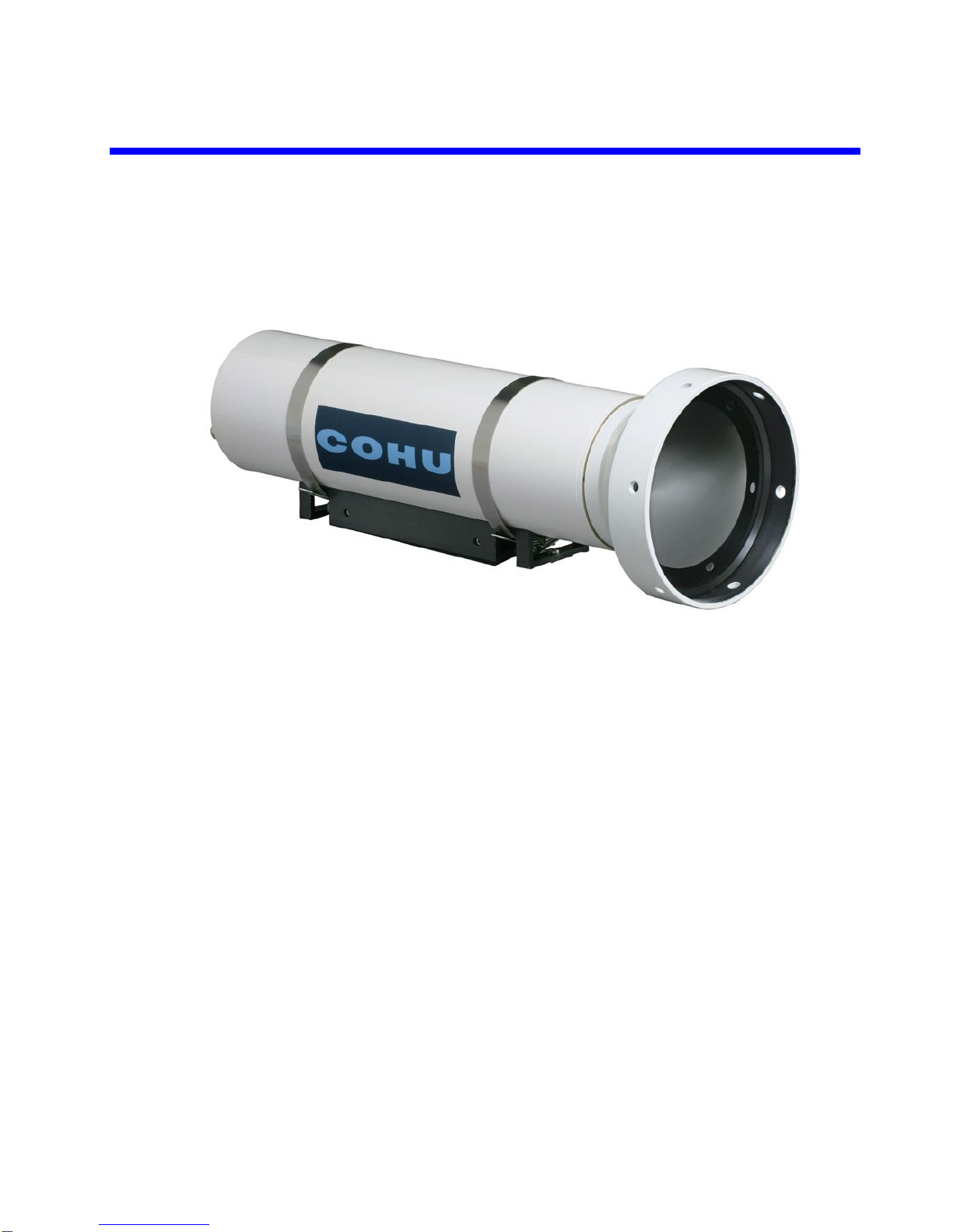
5930 Series Thermal Camera User's Manual
Cohu Electronics PAGE 2OF 17
3912 Calle Fortunada
San Diego, CA 92123-1827
Phone: 858-277-6700
Fax: 858-277-0221
Table of Contents
Product Description.......................................................................................................................................4
1.1 FPA Description............................................................................................................................4
1.2 Hardware Description ...................................................................................................................4
1.2.1 FPA Support PCB.........................................................................................................................4
1.2.2 Camera Controller PCB................................................................................................................4
1.2.3 Camera Support PCB...................................................................................................................5
1.2.4 Camera Power Supply PCB .........................................................................................................6
1.3 Camera Operation ........................................................................................................................6
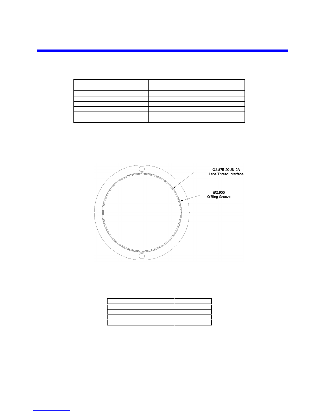
1.4 Lens Options.................................................................................................................................6
1.5 Camera Performance ...................................................................................................................7
1.6 Mechanical Characteristics...........................................................................................................8
2. Installation.....................................................................................................................................8
2.1 Unpacking and Receiving Inspection............................................................................................8
2.2 Lens Cleaning...............................................................................................................................8
2.3 Electrostatic Discharge (ESD) Precautions..................................................................................9
2.4 Tripod Mounting Interface.............................................................................................................9
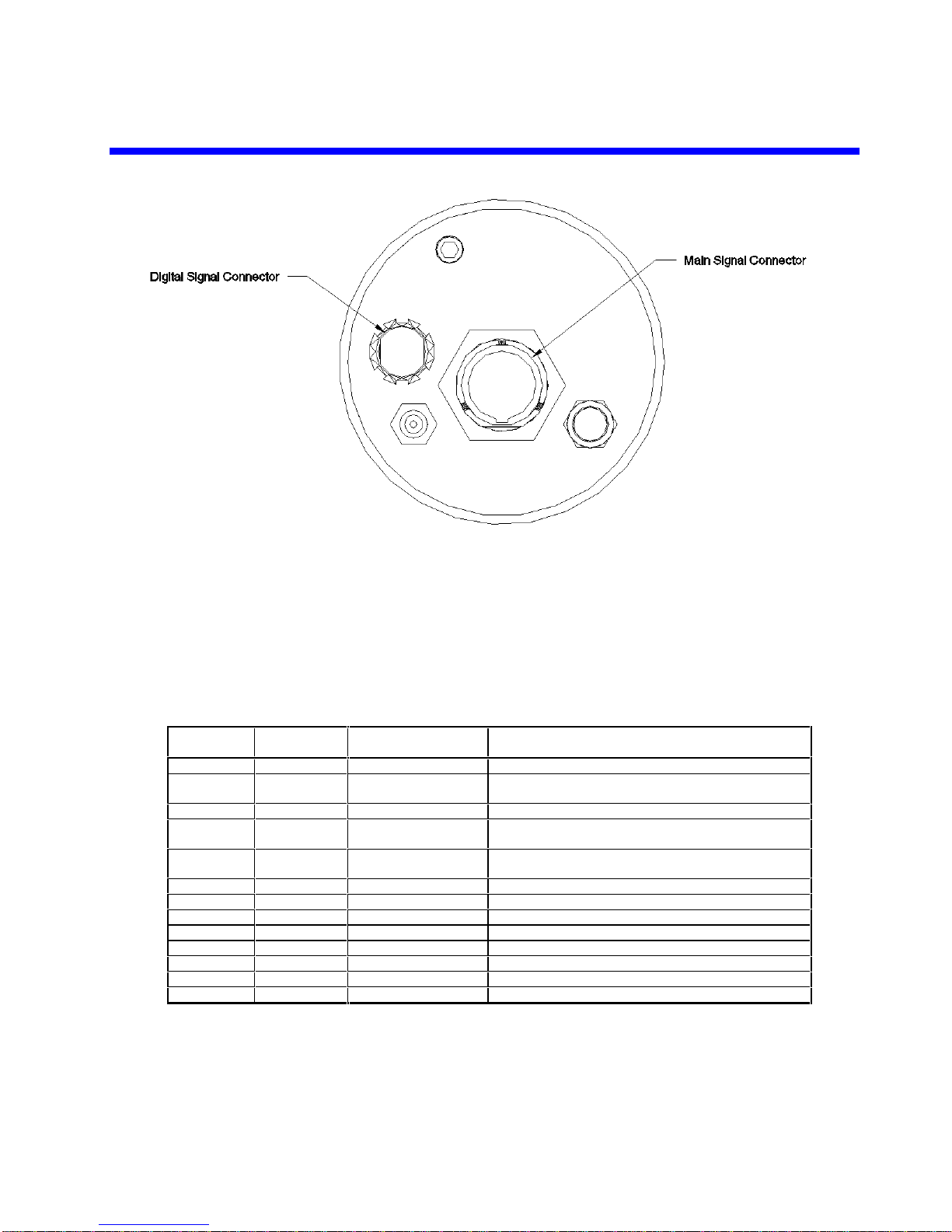
2.5 Main Rear Panel Signal Connector ..............................................................................................9
2.5.1 Camera Main Signal Connector..................................................................................................10
2.5.2 Mating Rear Panel Connector ....................................................................................................11
2.6 Main Rear Panel Digital Signal Connector .................................................................................11
2.6.1 Camera Digital Signal Connector ...............................................................................................11
2.6.2 Mating Digital Signal Connector .................................................................................................12
2.7 Power Input Selection.................................................................................................................12
2.7.1 AC Line Input Voltage Connections............................................................................................12
2.7.2 24VAC Input Voltage Connections.............................................................................................12
3. Camera Software Features.........................................................................................................13
4. Environmental Specifications......................................................................................................15
4.1 Temperature ...............................................................................................................................15
4.2 Water Resistance........................................................................................................................15
4.3 Relative Humidity........................................................................................................................15
4.4 Shock and Vibration....................................................................................................................16