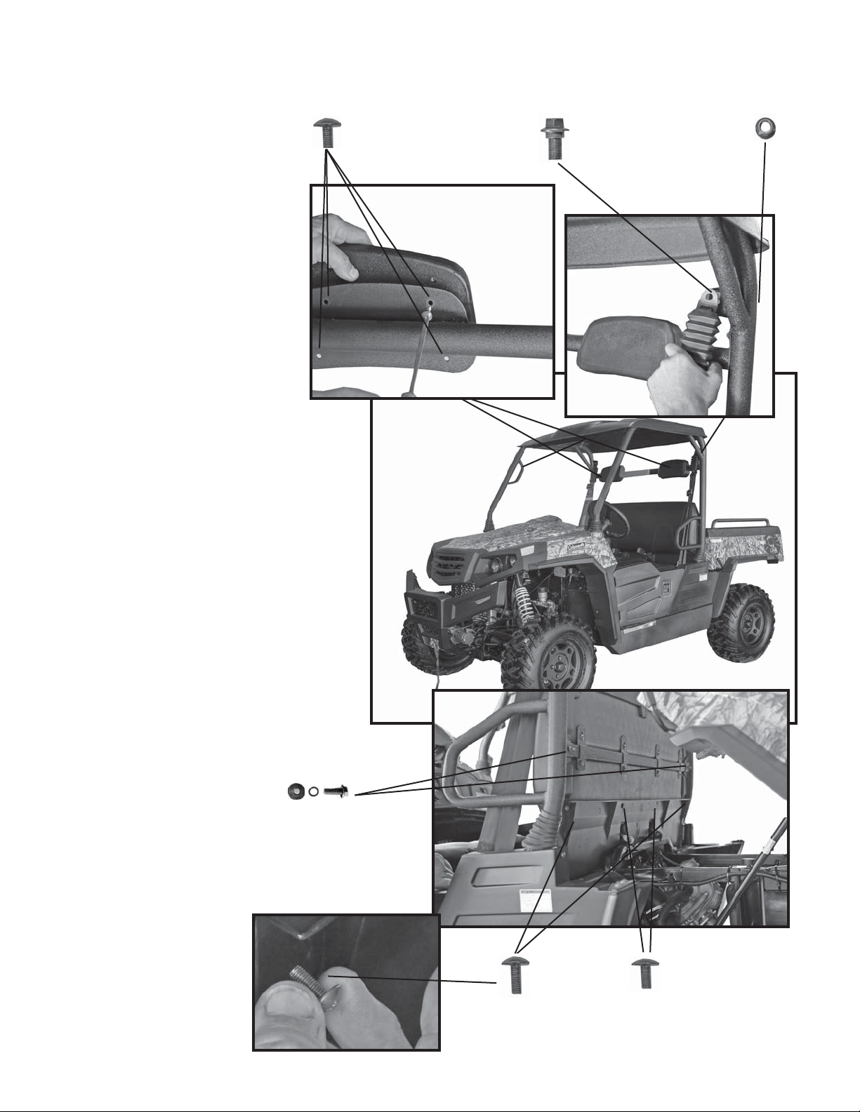
Coleman OUTFITTER 550 User manual

For questions regarding these assembly
instructions, please contact Coleman Powersports
Phone: (888) 405-8725 / Email: [email protected]
070618
OUTFITTER 550/750
ASSEMBLY INSTRUCTIONS

UTV Chassis
Seat back and bench seat
Mirrors
Front Bumper and Bars
Front Roll
Cage Boots
Rear Roll
Cage Boots
Roll Cage
Assembly
PARTS
Battery, Electrolyte & Bracket
Head Rests
Hardware Pack
Steering Wheel
Windshield
1

1
2
5
8
1
3
4
7
10
12
14 15 16 17 18 19
6
9
11
13
HARDWARE KIT REFERENCE
Ref. 19 M6 Lock Washer QTY. 2
Ref. 1 M10X45 Allen Head Bolt QTY. 4 Ref. 10 M6X20 Screw QTY. 8
Ref. 2 M8 Shoulder Bolt QTY. 2 Ref. 11 M8 Lock Nut QTY. 2
Ref. 3 M8 Shoulder Nut QTY. 2 Ref. 12 M10 Cap Nut QTY. 4
Ref. 4 M10X25 Bolt QTY. 4 Ref. 13 M10 Lock Nut QTY. 4
Ref. 5 M10 Shoulder Bolt QTY. 2 Ref. 14 M10 Concave Washer QTY. 4
Ref. 6 M6X16 Bolts QTY. 4 Ref. 15 Rubber Battery Pads QTY. 2
Ref. 7 M6X20 Wing Bolt QTY. 4 Ref. 16 M6 Flat Washer QTY. 6
Ref. 8 M8X20 Bolt QTY. 2 Ref. 17 M10 Flat Washer QTY. 4
Ref. 9 M10X20 Bolt (Spares) QTY. 2 Ref. 18 M10 Lock Washer QTY. 4
2

STEERING WHEEL INSTALLATION
Steering wheel
Center Horn
Clamp ring
Horn wire
Connector
Tools needed:
4mm - Allen Head Wrench
1. Install horn in steering wheel and attach horn
wire (located in the steering column) to back of
horn.
2. Install steering wheel with large open area on
top portion of steering wheel, facing up.
3. Insert and loosely tighten top and bottom
bolts in steering assembly
Top and Bottom
Bolts
Rotate steering column to
line up holes 2 O,Clock and
8 O,Clock
4. Rotate steering collar (piece directly behind
steering wheel, on the column) and install allen
bolts at 2 o’clock and 8 o’clock position through
the clamp ring.
Note: If these 2 bolts are not installed the
steering collar will rotate freely and the bolts
will not be secure..
5. Install remaining bolts through the clamp
ring and tighten all securely.
Line up
Steering Column
Note: Before steering wheel install, make sure
the front tires are straight and in line with the rear
tires.
Uninstall the 6 - M5X20 allen bolts and clamp
ring from the steering column.
3

1. While on the ground, place front and
rear roll cage boots onto the appropriate
bars.
2. With assistance, lift the cage assembly
onto the mounting locations.
Note: The rear points install through the
bars vertically and the front points are
side by side.
Front roll
cage boot
Rear roll
cage boot
Roll cage
assembly
ROLL CAGE INSTALL
M10 Lock Washer
(Hardware Fig. #18)
M10 Flat Washer
(Hardware Fig. #17)
M10 Cap Nut
(Hardware Fig. #12)
M10X45
Allen head bolt
(Hardware Fig. #1) 2 - M10 Concave Washer
(Hardware Fig. #14)
M8 Shoulder Bolt
(Hardware Fig. #2)
M8 Shoulder Nut
(Hardware Fig. #3)
Tools needed:
8mm - Allen Head Wrench
16mm Socket/Wrench
Note: Cap nuts should face to
the front of the UTV. This
will allow the rubber boot to fit
properly
4
3. Install roll cage with hardware provided.
Note: Do not tighten any hardware until
all hardware is in place.

2 - M6X20
Seat back screws
(outer)
1. Attach head rests to roll cage
assembly using M6X15 screws.
2. Attach back rest to roll cage
using M6X16 bolts, M8 spring
washers and M8 flat washers.
3. Attach rear plastic backing to
rear of seat back using 2 - M6X20
Screws (outer) and 2 - M6X12
Screws (inner.)
Note: M6X20 and M6X12 Screws
are already installed on seat back.
They must be removed and
reinstalled during this process.
4. Attach seat belt assembly to roll
cage using M10 shoulder bolt and
M10 lock nut.
Note: Take care in alignment of the
seat belt. Make sure it isn’t twisted
prior to install. The top curved
mount should be curving toward
the front of the UTV after install.
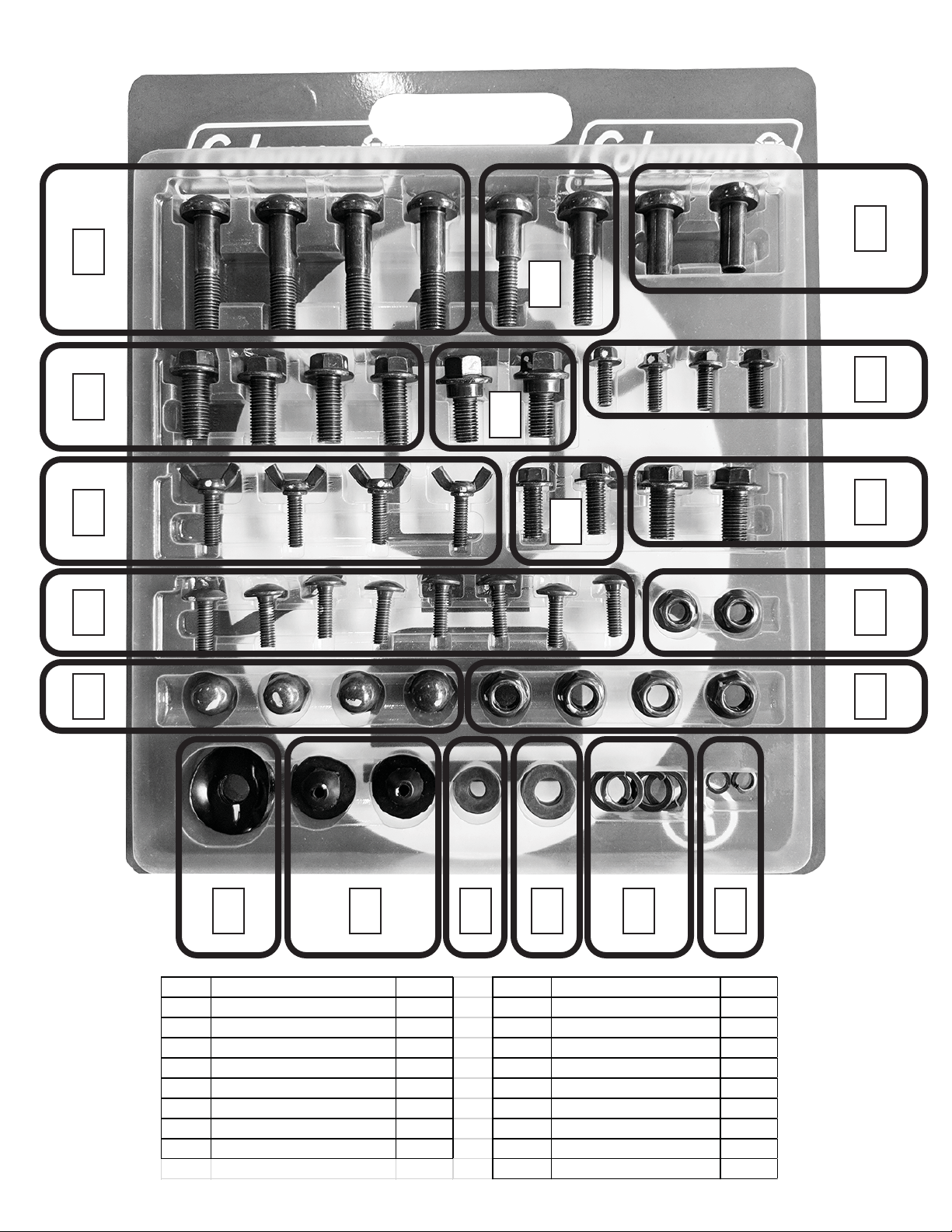
2 - M6X16 Bolts (Hardware Fig. #6)
2 - M6 Lock Washers (Hardware Fig. #19)
2 - M6 Flat Washers (Hardware Fig. #16)
4 - M6X15 Screws (per side)
(Hardware Fig. #10)
HEADRESTS, SEAT BELTS AND SEAT BACK ATTACHMENT
Tools needed:
10mm Socket/Wrench
12mm Socket/ Wrench
14mm Socket/Wrench
Phillips screw driver
M10 Shoulder Bolt (per side)
(Hardware Fig. #5)
M10 Lock Nut (per side)
(Hardware Fig. #13)
2 - M6X12
Seat back screws
(inner)
5

1. Install bumper bars on the inside
of both mounting points using M8X20
Bolts and M8 Lock Nuts.
Note: The flatter side of the bar
should be facing inside. The
circular mounting hole on the bar
is the bumper side mount. Do not
fully tighten bolts until bumper
is mounted.
2. Lift front bumper assembly in
place and attach the vehicle side
bumper bar mount with M10X25
Bolts and M10 Lock Nuts.
Note: The vehicle side bumper
bar should be mounted on the
outside. Do not fully tighten
until bottom mounts are secured.
3. Attach bottom of bumper
assembly with M10X25 Bolts.
4. Tighten bumper bar bolts and
nuts.
5. Attach wires to winch. Red wire
to top (+) and black wire to bottom
(-.)
6. Plug in headlight plugs and zip tie
wires to bumper bars.
Red wire to +
FRONT BUMPER INSTALL
Tools needed:
8mm Socket/Wrench
10mm Socket/Wrench
12mm Socket/Wrench
M8X20 Bolt (per side)
(Hardware Fig. #8)
M8 Lock Nut (per side)
(Hardware Fig. #11)
M10X25 Bolt
(per side)
(Hardware Fig. #4)
M10 Lock Nut (per side)
(Hardware Fig. #13)
2 - M10X25 Bolt
(Hardware Fig. #4)
Headlight plugs
Black wire to -
6

WINDSHIELD AND MIRROR INSTALL
3. Install buckle assemblies using
M6 Screws
Metal Washer
Bushing
Rubber
Grommet
Tools needed:
4mm Allen head wrench
Phillips screw driver
1. Insert Rubber Grommets in all
bracket holes in windshield.
Note: Hardware and parts for the
windshield are located in the the
Windshield box.
M6 Screws
Window buckles
2. Insert Metal washer bushings
through top of rubber bushings.
4. Install the rubber buckle
pads in each of the buckle
assemblies.
Buckle Pad
7

Bottom windshield
Mirror assembly
Top windshield
WINDSHIELD AND MIRROR INSTALL
Mirror bracket
Mirror
Note: Hardware and parts for the Mirror
are located in the the Mirror package.
8
7. After Mirrors are installed
attach top portion of windshield
to UTV.
5. Install bottom portion of
windshield on UTV
6. Install left and right mirrors at
the top portion of the bottom
windshield assembly.

1. Place battery in battery box under driver side
seat area and press rubber pads into battery bracket.
2. Secure battery in place with battery
bracket and 2 - M6X16 Bolts
5. Re-install battery cover and secure with M6X20
Wing Bolts and M6 Flat Washers.
6. Install M6X20 Wing Bolts and M6 Flat
Washers on passenger side fuel pump
cover.
Rubber Pads
for Battery
(Hardware Fig. #15)
Battery
Positive (+)
Red
Negative (-)
Black
Tools needed:
8 mm Socket/Wrench
10mm Socket/Wrench
2 - M6X16 Bolt
(Hardware Fig. #6)
2 - M6 Flat Washer
(per side)
(Hardware Fig. #16)
2 - M6X20 Wing Bolt
(per side)
(Hardware Fig. #7)
9
Note: Follow manufacturer’s instructions
on preparing battery with fluid before
installation. .
BATTERY INSTALLATION
4. The 3 black wires attach to
NEGATIVE (-)terminal.
3. The 3 red wires attach to
POSITIVE(+) terminal.
WARNING! ALWAYS ATTACH RED
POSITIVE (+) WIRES BEFORE
BLACK NEGATIVE (-) WIRES TO
BATTERY.

PARTS SCHEMATIC REFERENCE
10
This manual suits for next models
1
Table of contents
Popular Automobile Accessories manuals by other brands

Barite
Barite 83051 user manual

Lund Industries
Lund Industries Headlight Flasher AT-500 installation instructions

Twinny Load
Twinny Load A 39 Fitting instructions

Safe Fleet
Safe Fleet Prime Design FBM-1026 manual

Lund
Lund Interceptor installation instructions

Kleinn Air Horns
Kleinn Air Horns RNGR-102-1/220 installation manual

Lippert Components
Lippert Components Sliding Swivel Seat Base owner's manual

Toyota
Toyota PT546-52080 manual

Paxton Automotive
Paxton Automotive Novi Supercharger Owner's installation guide

Mercedes-Benz
Mercedes-Benz SEAT BELTS AND AIRBAGS user manual

Saris
Saris BONES 3 Assembly instructions

aqprox!
aqprox! appUSBCAR24B user guide