ATTENTION: Do not use pump when pool is in use.
During the season of use of the swimming pool, the filtration system must be necessarily put into
service every day, enough for a long time to assure at least a complete renewal of the volume of water.
Repair
Check pool for any leaks from valves or seams, check the ground cloth for any evident water
loss. Do not add chemicals until this has been done.
NOTE: In the event of a leak, patch your pool using the underwater adhesive
repair patch provided. Refer to the FAQs for further information.
Dismantling
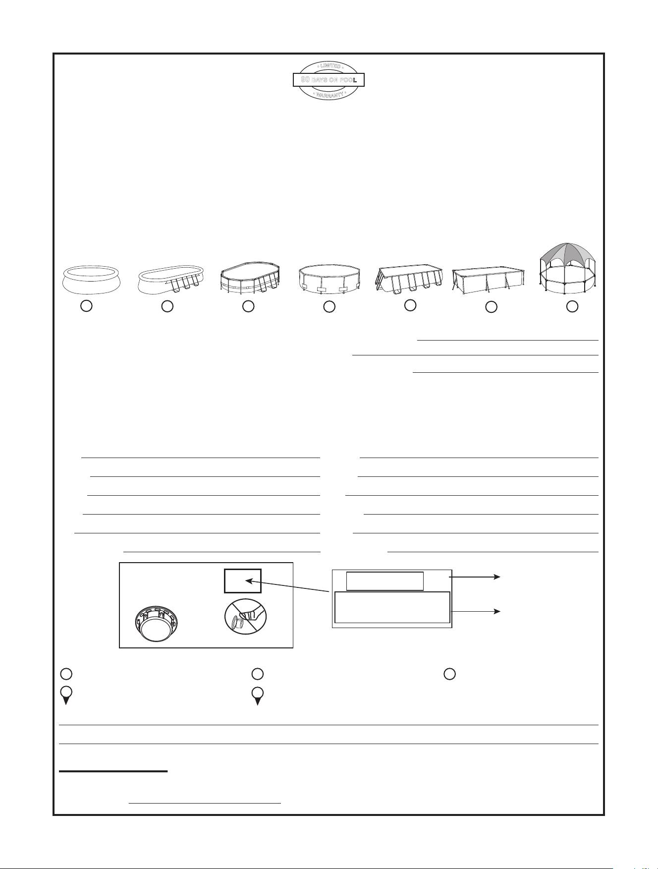
1. Unscrew the drain valve cap on the outside of the pool counter clockwise and remove.
2. Connect the adaptor to the hose and put the other end of the hose in the area where you are
going to drain your pool. (Check local regulations for drainage by-laws).
3. Screw the control ring of the hose adaptor clockwise onto the drain valve. The drain valve will
be open and water will start to drain automatically.
ATTENTION: Water flow can be controlled with the control ring.
4. When draining is finished, unscrew the control ring to close the valve.
5. Disconnect the hose.
6. Screw the cap back onto the drain valve.
7. Air dry pool.
ATTENTION: Do not leave the drained pool outside.
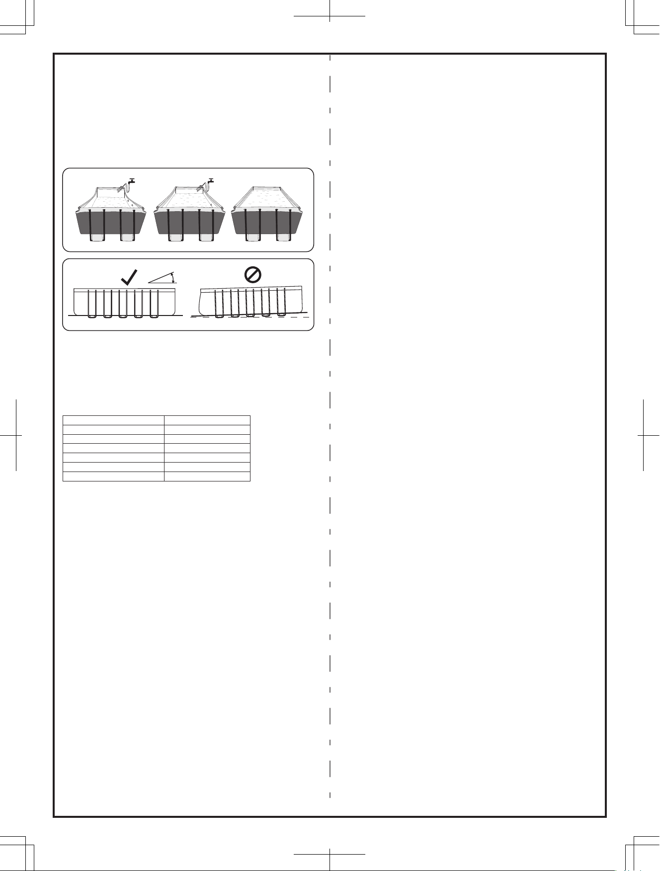
TEST
pH value
Cyanuric acid
Free chlorine
Chlorine compound
Algae
Calcium hardness
IDEAL VALUES
7.4– 7.6
30 – 50 ppm
2 – 4 ppm
0
None visible
200 – 400 ppm
Pool Maintenance
If you do not adhere to the maintenance guidelines below, your health might be at risk, especially
that of your children.
IMPORTANT: If you don’t respect the ideal values of the water chemicals the PVC
can be damaged and become discolor.
The following table lists the sequence of the tests that should be carried out for the ideal values
and possible actions. Regularly check the pH value and chlorine concentration weekly and adjust
to the ideal values.
To keep your pool clean:
1. Contact your local pool supply shop for advice and purchase of chemicals and pH kits.One of
the most important factors to increase the life of the liner is to keep continously clean and
healthy water. Please strictly follow the instructions from professional technicians for the water
treatment through the use of chemicals.
2. Locate a bucket of water next to pool to clean users’ feet before entering pool.
3. Cover the pool when not in use.
4. Skim pool regularly to avoid settled dirt.
5. Check and wash the filter cartridge regularly.
6. Gently clean any scum from below the top ring with a clean cloth.
7. Please be careful in case of rain water, kindly check that the water level is not higher than the
expected. If so, YOU HAVE TO DISCHARGE THE EXCESS WATER
Proper maintenance can maximize the life of your pool.
During the season of use of the swimming pool, the filtration system must be necessarily put into
service every day, enough time to assure at least a complete renewal of the volume of water.
Storage and Winterization
1. Please remove all the accessories and spare parts of the pool and store them clean and dry.
2. Once pool is completely dry, sprinkle with talcum powder to prevent pool from sticking together,
fold pool carefully. If pool is not completely dry, mold may result and will damage the pool liner.
3. Store liner and accessories in a dry place with a moderate temperature between 5ºC / 41ºF
and 38ºC / 100ºF.
4. During the rainy season, pool and accessories should be stored as per above instructions also.
5. Improper draining of the pool might cause serious personal injury and/or damage to personal
property.
6. We strongly recommend the pool is disassembled during the off season (winter months). Store
in a dry location out of children’s reach.
Frequently Asked Questions
1. What is a suitable base for the Rectangular Frame pool?
Almost any completely flat, solid, level surface can be used. Do not use sand as a leveling
material as it is prone to shifting under the pool. The ground should be dug out until it is perfectly
level. Do not set up on driveways, decks, platforms, gravel or asphalt. The ground should be firm
enough to withstand the weight and pressure of the water: mud, sand, soft / loose soil or tar are
not suitable. A concrete base can be used but care should be taken not to drag the pool across
the surface as abrasions could tear the liner. If the pool is to be set up on a lawn, it is
recommended that the grass is removed from where the pool will sit as it will die and may cause
odors / slime. Certain types of hardy grass can grow through the liner as can aggressive bushes /
plants by the side of the pool. Ensure adjacent vegetation is cut back where necessary. Use of a
ground cloth assists in protecting the base of the pool.
2. How will I know if my pool is set up on unleveled ground?
If your pool appears to be bulging on one side it is not set up on level ground. It is important
that you empty your pool and move the pool to a level site. If the pool is not on level ground it will
place undue stress on the seams and could result in the seams bursting which will cause
flooding, property damage and potentially personal injury or death.
Fill your pool following the instructions in the owner’s manual carefully. This will ensure that you
do not waste water and the pool can be moved easily so that the ground can be leveled at an
appropriate time and not after you have completely filled it with water.
3. Can I have my pool filled by a water service?
We recommend using a garden hose under low pressure for filling your pool. If it is necessary
to use a water delivery service, it is best to fill the pool with one inch of water by hose and smooth
wrinkles first. Use a water service that is able to regulate the flow of water to prevent damage.
Ensure you stop at each step as noted in the instruction manual to ensure your pool is level.
Bestway will not be held responsible for pools damaged or weakened by water delivery services.
4. What is the maximum fill height of the pool?
Fill pool until water capacity is 90% top rail. Never attempt to fill your pool beyond the base of
the rail. We recommend leaving extra room to account for water displacement when occupants
are inside the pool. You may have to top up the water during the season which has been lost
through evaporation or normal use.
5. My pool is leaking, what do I do to fix it?
The pool does not need to be emptied to fix any holes. Self-adhesive underwater repair
patches can be purchased at your local pool / hardware store. For external use, use the repair
patch provided. For internal holes, clean the hole on the inside of the pool to wipe off any oils and
algae. Cut a circle large enough to cover the hole and apply the patch securely onto the side in
the water. Cut a second patch and apply to the outside of the pool for extra strength. If the hole is
in the base of the pool use one patch only and weigh it down with a heavy object while it bonds. If
you have patched the pool when it is empty we recommend you leave it at least 12 hours before
filling.
6. Where can I buy filter cartridges and how often should I change them?
Filter cartridges to fit your filter pump should be available from the store where you purchased
your pool. If not, most mass retailers sell filter cartridges as an accessory. If you are unable to
obtain replacements please call our toll-free number and we will assist you in finding a source
local to you. The cartridges should be changed every 2 weeks dependent upon use of the pool.
Check the filter on a weekly basis and clean by hosing down any debris and particles.
Note: Ensure your pump is disconnected from the electrical supply before checking the
filter cartridge.
7. How many times a year should I change the water?
This is dependant on the amount of use the pool receives, and the attention paid to covering
the pool and keeping chemicals properly balanced. If maintained correctly the water should last a
full summer season. Please contact your local pool chemical supplier for detailed information
regarding chemicals, they will be able to advise you how to best maintain the cleanliness of your
water.
8. Do I need to take my pool down for the winter?
Yes, Above-ground pools may collapse under the weight of ice and snow and the PVC walls
will be damaged. We recommend taking the pool down when temperatures fall below 8ºC / 45ºF.
The pool should be stored indoors in a moderate temperature between 5ºC / 41ºF and 38ºC /
100ºF. Please store away from chemicals and rodents and out of the reach of children.
9. My pool is fading – why is that?
Excessive use of chemicals can cause the color of the inside of the liner to fade; this is similar
to a swimsuit fading over time from repeated contact with chlorinated water.
10. How many years will the pool last?
There is no set time limit for the pool to last; following the instructions in the owner’s manual
and with proper care, maintenance and storage you can considerably increase the life of your
pool. Improper set-up, use or care can result in failure of the pool.
11. Do you recommend the use of a filter pump with a Bestway pool?
Absolutely! We strongly recommend you use a filter pump which will maintain the cleanliness
of the water.
12. Which are the most important functions of my filter pump?
The most important function of a filter pump is the elimination of every sort of impurity from
the water with the aid of a filter cartridge and chemical products for its sterilization.
6
Filling Pool with Water
ATTENTION: Do not leave pool unattended while filling with water.
1. Fill pool until water capacity is 90%, DO NOT OVERFILL as this could cause the pool to collapse.
In tim
es of heavy rainfall you may
need to empty some of the water to ensure the level is correct. (See Fig. 7)
2. When filling the
pool is completed, check that
the water is not collecting on any side to ensure the pool is level.
IMPORTANT: If pool is not level, drain water and re-level ground by digging out (See Fig. 8).
Never attempt to move the pool with water in it, serious personal injury or damage to the pool may result.
WARNING: Your pool may contain a great deal of pressure. If your pool has any bulge or
uneven side then the pool is not level, the sides may burst and the water may discharge suddenly causing
serious personal injury and/or damage to property.
3. Check pool for any leaks at valves or seams, check ground cloth for any evident water loss. Do not add
chemicals until this has been done.
NOTE: In the event of a leak, patch your pool using the underwater adhesive repair patch provided.
Refer to the FAQ’s for further information.
S-S-004357/21.0x28.5cm / 90397E/ 矩形支架水池说明书 Coleman版JS-YF-2016-B-02556/英
S-S-004357
Fig. 8
0°
30% 70% 90%
Fig.7