V3
t
+44 (0) 1604 495 151 I f+44 (0) 1604 495 095 I e[email protected] I wcollingwoodlighting.comCollingwood Lighting, Brooklands House, Sywell Aerodrome, Sywell, Northampton NN6 0BT, United Kingdom
t+33 (0) 4 816 816 10 I f+33 (0) 4 816 816 11 I eventes@collingwoodgroup.com I wcollingwoodlighting.com
Collingwood Lighting, 43-47 Avenue de la Grande Armée, 75116, Paris, France
en
fr
2 year warranty
2 ans de garantie
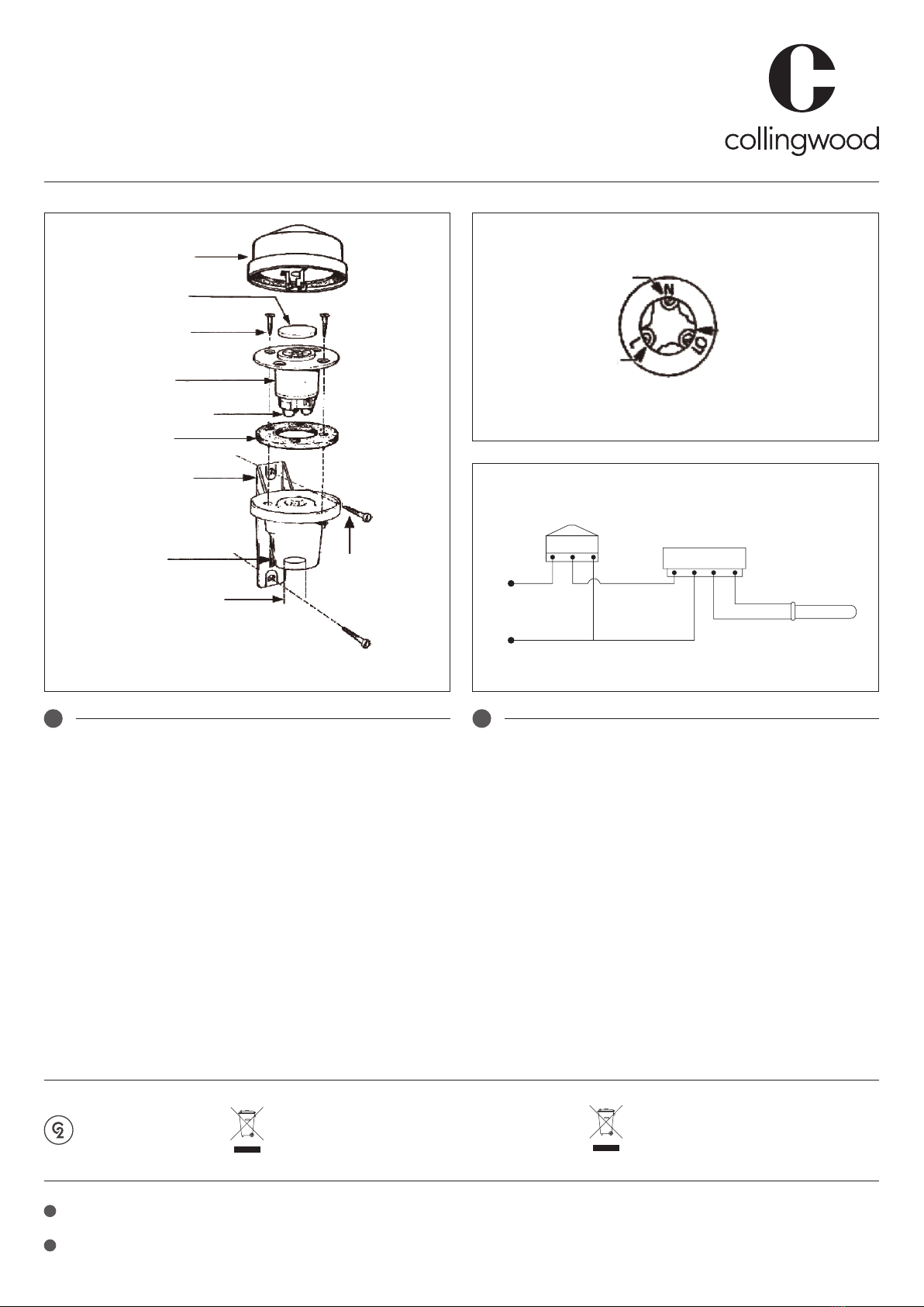
Fig 1. Fig 3.
Fig 2.
Disposal of this product should be separate from household waste.
Please separate these items from other types of waste and recycle
them responsibly to promote the sustainable reuse of material
resource. Household users should contact their local government
office for details of where and how they can take these items for
environmentally safe recycling.
Ce produit ne doit pas être éliminé avec les ordures ménagères.
Merci de le séparer des autres déchets et de le recycler de manière
responsable afin de promouvoir la réutilisation des ressources
matérielles. Les consommateurs doivent contacter leurs autorités
locales pour plus d’information quant aux lieux et méthodes de
recyclage en accord avec la protection de l’environnement.
Ballast / LED Driver
Ballast / driver LED
Photocell Kit | Kit de cellules photoélectriques
Installation instructions I Consignes d’installation
Light ing/
Luminaire
Photocell/
Cellule photoélectrique
L NLO
L
N
Neutral/
Neutre
Live/
Phase
Load/
Charge
Control unit/
Commande
Plug cover discard when
connecting control unit/
Enlever l’obturateur pour la
connexion de la commande
Mains cable entry
Alternative 20mm Conduit entry/
Entrée de câble d’alimentation
Entrée de conduit 20mm
2-Socket xing screws/
Vis pour xation de la che
(x2)
Socket/
Fiche
Gasket/
Joint
Wiring terminals (see diagram)/
Bornes de câblage (voir schéma)
Base holder bracket/
Support de xation
de la base
Base/
Base Bracket xing screws/
Vis de xation du
support
The kit consist of 3 parts-control unit, socket
and baseholder/ bracket
Le kit se compose de 3 éléments : la commande, la
che et le support/xation de la base
en fr
Installation
1. Important: This unit must be wired by a qualified electrician or suitable competent
person. Isolate the mains supply prior to wiring.
2. Choose a suitable location and establish a mains supply to the photocell unit.
Take care to avoid locations where the photocell unit will be exposed to other light
sources e.g. another light fitting.
Note: Photocell unit operates best when located out of direct sunlight.
3. Remove control unit section from base section (twist anti-clockwise and pull away)
4. Mark and drill two mounting holes for the lower section using the base holder bracket as
a template and fix to mounting surface.
Drill size (clearance hole) for the supplied screws is: Ø4mm.
Drill size for the supplied wall plugs is: Ø6mm.
5. Remove the socket section by unscrewing the 2x fixing screws.
6. Feed the mains and load cabling into the base of the product and proceed to wire in the
mains cable and load cable into the wiring terminals. (Fig 2 / Fig 3)
Note: Base section will accept M20 gland and conduit fittings (not supplied).
7. Fix the socket section back into the base section using two screws previously removed.
Ensure gasket is fitted between socket and base sections.
8. Fix the control unit section back onto the base section (match up large pin with large
hole, push control unit onto base and twist clockwise).
9. Switch on mains power.
10. Test unit operation by covering cell completely with opaque cover (box packaging can be
used for this purpose) and waiting for 40-60 seconds.
Connected light fitting will turn on when <20-80 LUX is detected.
Installation
1. Important : cette unité doit être câblée par un électricien qualifié ou une personne
compétente. Isolez l’alimentation secteur avant de procéder au câblage.
2. Choisissez un emplacement approprié et établissez une alimentation secteur pour la
cellule photoélectrique. Évitez l’exposition à d’autres sources de lumière, par ex. un autre
luminaire.
Remarque : le fonctionnement de la cellule photoélectrique est optimal lorsqu’elle est
placée à l’abri de la lumière directe du soleil.
3. Retirez la commande de la base (tournez dans le sens inverse des aiguilles d’une montre
et tirez).
4. Marquez et percez deux trous de montage pour la partie basse en utilisant le support de
fixation de la base comme modèle. Fixez à la surface de montage.
Le diamètre de perçage (trou de dégagement) pour les vis fournies est de 4 mm.
Le diamètre de perçage pour les chevilles murales fournies est de 6 mm.
5. Retirez la fiche en dévissant les 2 vis de fixation.
6. Introduisez le câble d’alimentation et le câble de charge à la base du produit et
raccordez-les aux bornes (fig. 2 / fig. 3).
Remarque : la base accepte les raccords M20 et les presse-étoupes (non-fourni).
7. Fixez la fiche à la base à l’aide des deux vis retirées précédemment. Assurez-vous de
placer le joint entre la fiche et la base.
8. Fixez la commande à la base (insérez la grande broche dans le trou correspondant,
appuyez et tournez dans le sens des aiguilles d’une montre).
9. Allumez l’alimentation secteur.
10. Testez le fonctionnement de l’unité en couvrant complètement la cellule avec une
enveloppe opaque (par exemple une boîte d’emballage). Attendez 40-60 secondes.
Le luminaire connecté s’allume lorsque <20-80 LUX est détecté.