2.1.Safety Instructions
To reduce the risk of fire, electric shock, and injury, always follow basic safety precautions.
Remember to remove power from your computer by disconnecting the AC main source before removing or installing any equip-
ment from/to the computer chassis.
2.2.Preparing the Motherboard
The motherboard shipped in the box does not contain a CPU or memory. You need to purchase a CPU, a CPU fan assembly, and
memory to complete this installation.
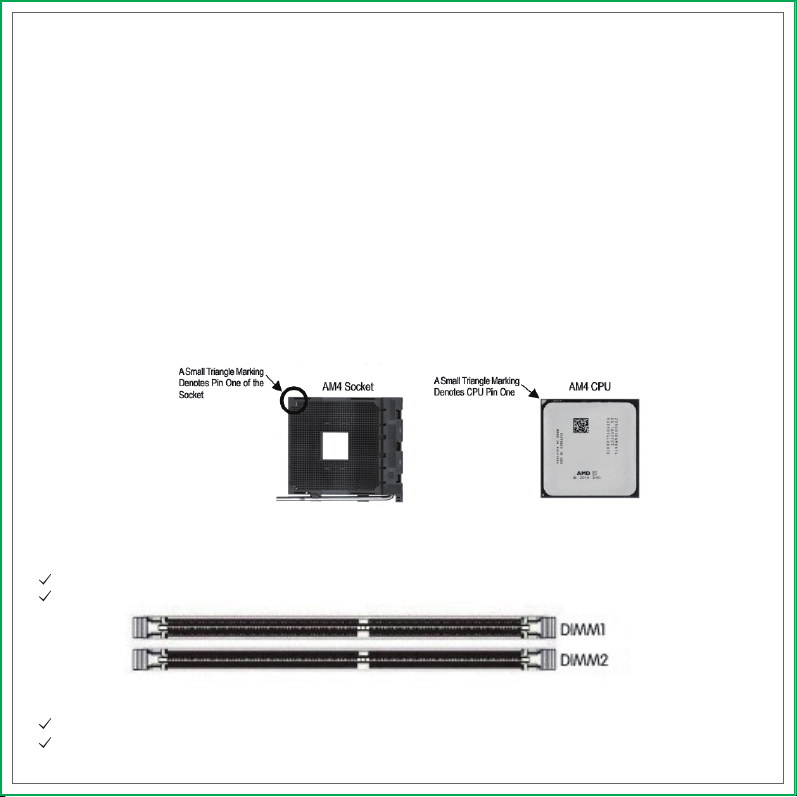
2.2.1.Installing the CPU
When installing a CPU, always remember to install a CPU heatsink. An CPU heatsink is necessary to prevent overheating and main-
tain system stability. Follow the steps below to ensure correct APU and heatsink installation. Wrong installation can damage both
the APU and the motherboard.
1. Pull the lever sideways away from the socket. Make sure to raise the lever up to a 90-degree angle.
2. Locate the pin one (denoted by a small triangle) of the CPU socket and the CPU..
3. If the CPU is correctly installed, the pins should be completely embedded into the socket and can not be seen. Please note that
any violation of the correct installation procedures may cause permanent damages to your motherboard.
4. Press the CPU down firmly into the socket and close the lever. As the CPU is likely to move while the lever is being closed, always
close the lever with your fingers pressing tightly on top of the CPU to make sure the CPU is properly and completely embedded
into the socket.
5. Locate the CPU fan connector on the motherboard.
6. Position the cooling set onto the retention mechanism. Hook one end of the clip to hook first.
7. Then press down the other end of the clip to fasten the cooling set on the top of the retention mechanism. Locate the Fix Lever
and lift up it.
8. Fasten down the lever.
9. Attach the CPU Fan cable to the CPU fan connector on the motherboard.
This section will guide you through the installation of the motherboard. The topics covered in this section are:
Preparing the motherboard
Installing the CPU
Installing the CPU fan
Installing the memory
Installing the motherboard
Connecting cables and setting switches
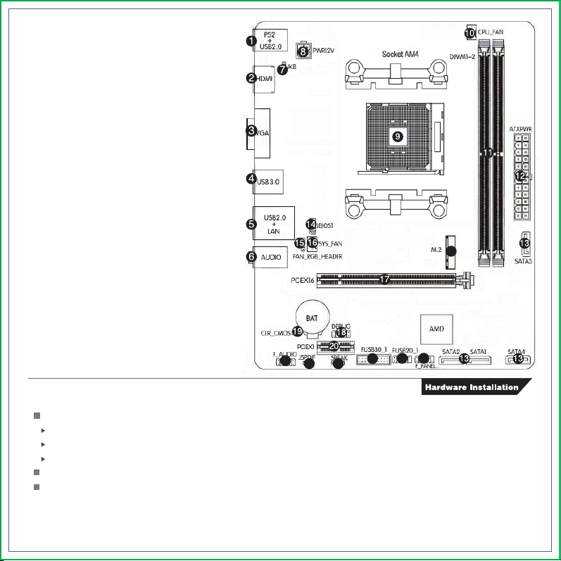
1、PS/2 Mouse/Keyboard and USB2.0 ports
2、Connect to HDMI monitor
3、Connect to VGA monitor
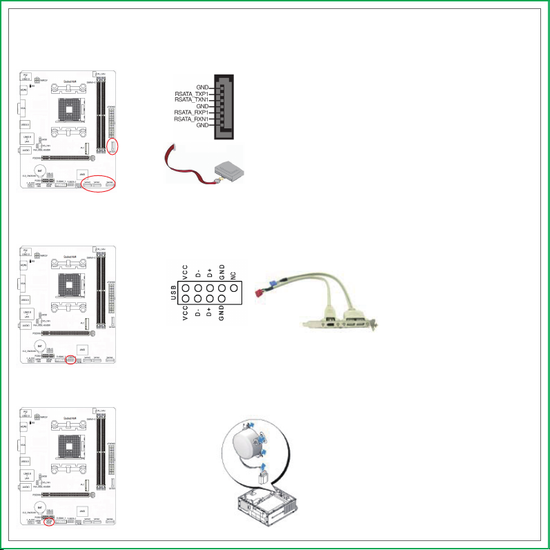
4、Connect to USB3.0 devices
5、Connect to USB2.0 devices and LAN
6、Connect to audio devices
7、Power off charging and PS2 mouse
/keyboard wake up jumper
8、4-pin Power connector
9、AMD AM4 socket
10、CPU fan connector
11、DIMM slots (DDR4)
12、24-pin ATX Power connector
13、SATA3.0 ports
14、Flash Bios header
15、12V 4Pin RGB FAN header
16、System fan connector
17、PCI Express 3.0 X16 slot, for VGA Card
18、DEBUG header
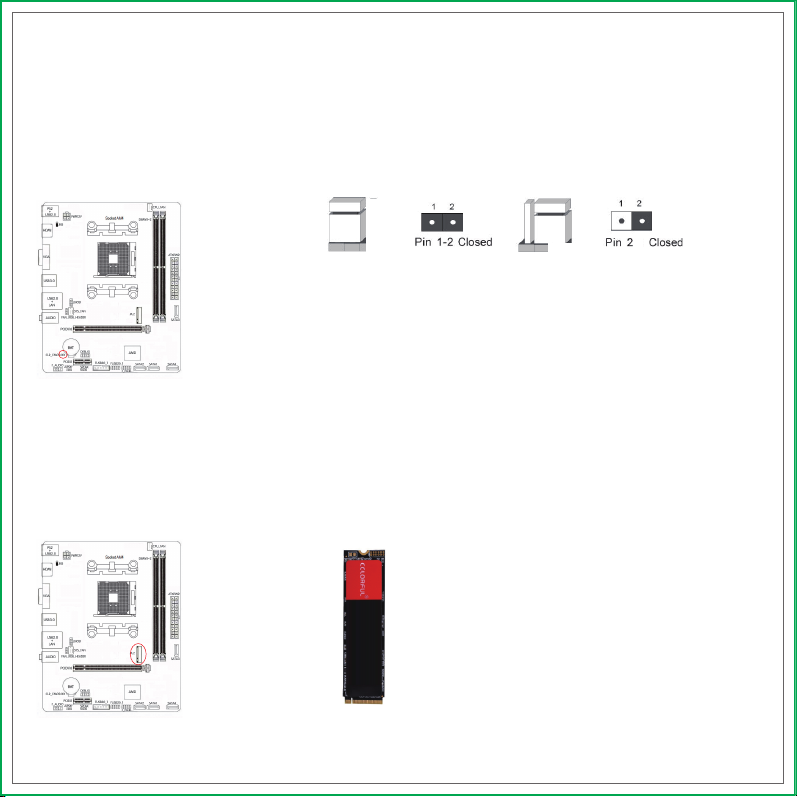
19、Clear CMOS jumper
20、PCI Express 3.0 X1 slot
21、Front panel audio connector
22、SPDIF header
23、Speaker connector
24、USB 3.0 header
25、USB 2.0 headers
26、Front power on / off , restart ,
indicator light header
27、M.2 slot
1.3.Motherboard Layout
21 22 23 24 25 26
27