GT-3600 G+
2-1
Chapter II Controls and Gauges
Content of Chapter
This chapter describes engine, hydraulic, and electrical
controls. It also gives the basic operating procedures
for the GT-3600. Read this chapter thoroughly to
identify the controls and operations. Pay particular
attention to all safety statements.
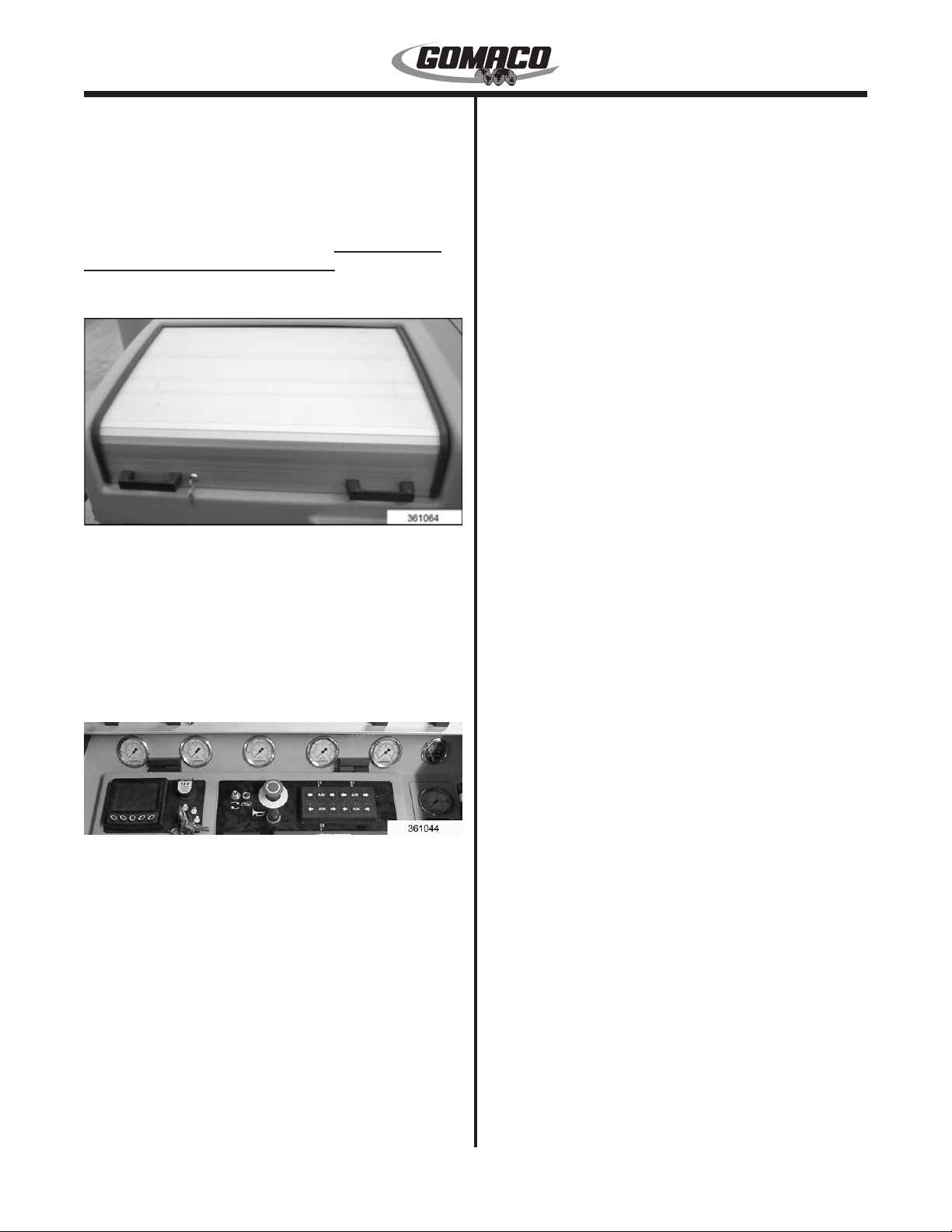
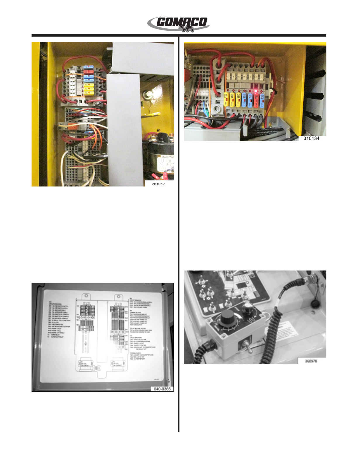
Control Console Cover
361064
The electrical control has a locking, sliding cover to
protect the switches and displays. To open, use the
key to turn the lock. Move the left handle toward the
key lock to unpin. Slide the panel upward. To close,
slide the cover all the way down. Move the left handle
away from the key lock to pin. Secure with the key
lock.
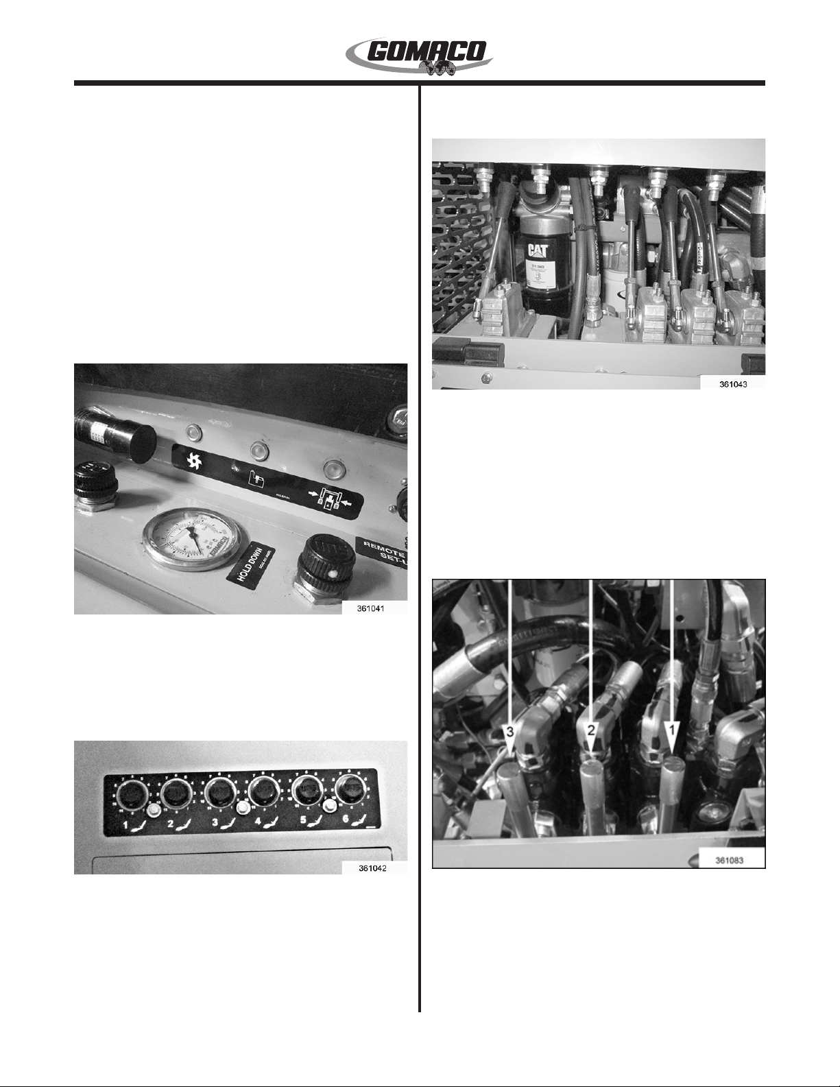
Hydraulic Controls and Gauges
361044
Vibrator Pressure Gauge: Monitors the amount
of pressure required to operate the vibrator circuit.
Amount of pressure required will depend on the
number of vibrators being operated and their speed.
Normal operating pressure range is 500 to 1500 psi
(34 to 103.4 bar). Stall pressure for the vibrator system
is 2000 psi (138 bar). One pump supplies oil to the
conveyor, vibrator and lift hydraulic systems.
Track Pressure Gauge: Monitors the amount of
pressure required to operate the track drive system in
forward or reverse. Normal operating pressure range
is 500 to 1800 psi (48 to 124 bar). Relief pressure
setting for the tractive system is 2500 psi (172 bar).
Conveyor Pressure Gauge: Monitors the amount of
pressure required to operate the charging conveyor.
Amount of pressure required will depend on the
amount of concrete on the conveyor. Normal operating
pressure range is 500 to 1800 psi (34 to 124 bar).
Relief pressure setting for the conveyor system is
2000 psi (138 bar). One pump supplies oil to the
conveyor, vibrator and lift hydraulic systems.
Note: If the machine is equipped with an auger
conveyor, the relief pressure setting on the pump
is increased to 2200 psi (151 bar).
Trimmerhead Pressure Gauge: Monitors pressure
required to drive the trimmer wheel. Normal operating
pressure range is 500 to 2500 psi (34 to 172 bar).
Pressure will vary depending on depth of cut, width
of cut, grade density and forward travel speed. Relief
pressure setting for the trimmer system is 3600 psi
(248 bar).
Lift Pressure Gauge: Monitors the amount of
hydraulic pressure available for machine elevation and
steering control. Normal lift pressure is 2000 psi (138
bar). One pump supplies oil to the conveyor, vibrator
and lift hydraulic systems.
Note: If the lift pressure drops below 1500 PSI
(103 bar), the machine control may become slow.
Hydraulic Oil Temperature Gauge: Monitors
the hydraulic oil temperature. Normal operating
temperature is 140° to 180° F (60° to 82° C)
depending on the ambient temperature. If the hydraulic
oil temperature rises above 195° F (90.5° C), locate
the cause of the overheating. Overheating can be
caused by excessive load on all systems on a warm
day, air ow through the oil cooler(s) restricted and/
or by a system that is constantly exceeding relief
pressure. The overheating can be corrected by
reducing the load on all systems on a warm day,
cleaning the oil cooler ns, and/or by reducing the load
on the various systems to maintain pressure below
relief setting.
Note: Excessive oil temperature may cause
serious damage to components.
Draw Bar Pressure Gauge: Monitors the amount of
pressure applied to the hydraulic cylinder holding the
front of the slipform mold down in contact with the
concrete. The regulated pressure range is 0 to 800 psi
(0 to 55 bar).
Drawbar Hold Down Pressure Control Valve: Used
to adjust the amount of pressure holding the front of
the slipform mold down on the concrete. Pressure