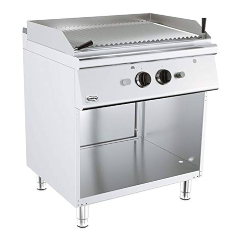
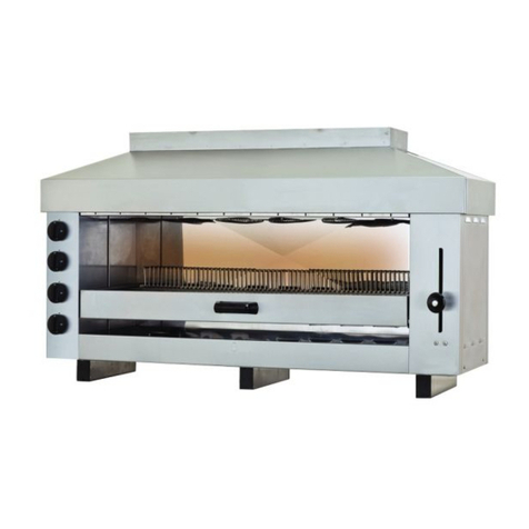
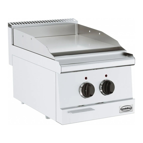
CombiSteel 7455.0900 User manual

Gas Grill
7455.0900 – 7455.0905 – 7455.0910 – 7455.0915
User Manual
Gebruikershandleiding
Gebrauchsanweisung
Le mode d’emploi

2
www.combisteel.com
CONTENT
ENGLISH
1INSTALLATION AND OPERATION MANUAL ..................................................................................................... 3
2INTRODUCTION.............................................................................................................................................. 5
3GENERAL INFORMATION................................................................................................................................ 6
4SPECIFICATIONS .............................................................................................................................................7
5OPERATING INSTRUCTIONS............................................................................................................................ 9
6OPERATOR MAINTENANCE .......................................................................................................................... 11
7SERVICE ........................................................................................................................................................13
8TROUBLE SHOOTING....................................................................................................................................15
NEDERLANDS
1INSTALLATIE- EN GEBRUIKERSHANDLEIDING ...............................................................................................16
2INTRODUCTIE ............................................................................................................................................... 18
3ALGEMENE INFORMATIE..............................................................................................................................19
4SPECIFICATIES...............................................................................................................................................20
5GEBRUIKSINSTRUCTIES ................................................................................................................................ 22
6BEDIENINGSONDERHOUD............................................................................................................................ 24
7SERVICE ........................................................................................................................................................26
8OPLOSSEN PROBLEMEN............................................................................................................................... 28
DEUTSCH
1INSTALLATIONS- UND BEDIENUNGSANLEITUNG.......................................................................................... 29
2EINLEITUNG.................................................................................................................................................. 31
3ALLGEMEINE INFORMATIONEN ................................................................................................................... 32
4SPEZIFIZIERUNGEN.......................................................................................................................................33
5BEDIENUNGSANWEISUNGEN....................................................................................................................... 35
6PFLEGE .........................................................................................................................................................37
7WARTUNG....................................................................................................................................................39
8PROBLEMBEHANDLUNG ..............................................................................................................................41
FRANÇAIS
1MANUEL D’INSTALLATION ET D’UTILISATION............................................................................................... 42
2INTRODUCTION............................................................................................................................................ 44
3INFORMATION GENERALE............................................................................................................................ 45
4SPECIFICATIONS ...........................................................................................................................................46
5INSTRUCTIONS DE FONCTIONNEMENT ....................................................................................................... 48
6OPÉRATEUR DE MAINTENANCE ................................................................................................................... 50
7SERVICE ........................................................................................................................................................52
8DÉPANNAGE .................................................................................................................................................54
EXPLODED VIEW (7455.0905)...............................................................................................................................55
BILL OF MATERIAL OF 7455.0905.......................................................................................................................... 56
EXPLODED VIEW (7455.0915)...............................................................................................................................57
BILL OF MATERIAL OF 7455.0915.......................................................................................................................... 58
EXPLODED VIEW (7455.0900)...............................................................................................................................59
BILL OF MATERIAL OF 7455.0900.......................................................................................................................... 60
EXPLODED VIEW (7455.0910)...............................................................................................................................61
BILL OF MATERIAL OF 7455.0910.......................................................................................................................... 62

3
www.combisteel.com
1 INSTALLATION AND OPERATION MANUAL
WARNINGS
IMPROPER INSTALLATION, ADJUSTMENT, ALTERATION, SERVICE OR
MAINTENANCE CAN CAUSE INJURY OR DEATH. THE INSTRUCTION MANUAL
MUST BE READ CAREFULLY BEFORE INSTALLING, OPERATING OR SERVICING
THIS EQUIPMENT
TO BE INSTALLED ONLY BY AN AUTHORISED PERSON IN ACCORDANCE WITH
AS 5601, LOCAL AUTHORITY, GAS, ELECTRICITY, ANY APPLICABLE STATUTORY
REGULATIONS AND MANUFACTURER REQUIREMENTS.
POST IN A PROMINENT LOCATION INSTRUCTIONS TO BE FOLLOWED IN THE
EVENT THE USER SMELLS GAS. THIS INFORMATION SHALL BE OBTAINED BY
CONSULTING THE LOCAL GAS SUPPLIER.
FOR YOUR SAFETY DO NOT STORE OR USE GASOLINE OR OTHER FLAMMABLE
VAPORS OR LIQUIDS IN THE VICINITY OF THIS OR ANY OTHER APPLIANCE
THIS EQUIPMENT IS DESIGNED FOR COMMERCIAL CATERING PURPOSES AND
WILL GENERATE SIGNIFICANT HEAT. HOT SURFACES WILL CAUSE BURNS.
A HAZARD AND RISK ASSESSMENT MUST BE UNDERTAKEN BY OWNERS AND
ALL OPERATORS MADE AWARE OF THESE.
DO NOT STORE OR USE FLAMMABLE LIQUIDS NEAR THIS APPLIANCE.

4
www.combisteel.com
DO NOT SPRAY AEROSOLS NEAR THIS APPLIANCE WHILE IT IS IN OPERATION.
INSTALLATION CLEARANCES AS SPECIFIED MUST BE OBSERVED.
IF YOU SMELL GAS, TURN THE UNIT OFF AND THE MAIN GAS SUPPLY VALVE TO
THE UNIT. CONTACT YOUR GAS SUPPLIER OR AN AUTHORISED PERSON.
BEFORE TURNING ON THE MAIN GAS SUPPLY, CHECK THE UNIT TO BE CERTAIN
THAT ALL THE VALVES ARE IN THE “OFF” POSITION.
PLEASE KEEP THIS MANUAL FOR FUTURE REFERENCE BY ALL OPERATORS.

5
www.combisteel.com
2 INTRODUCTION
Thank you for choosing this product and welcome you to the ever-growing customer circle. This product has
been specifically designed to meet a wide range of applications and represents the best quality and highest value
equipment.
Please read the instruction manual carefully to ensure the safe and reliable operation and performance of your
equipment.
Should you ever require service, you will be supported by trained and qualified service network – the largest
available.
We assure you of every support and wish you every business success.
2.1 GENERAL
The range is designed for commercial catering purposes and incorporates a wide range of design features.
2.2 WARANTY
This product is subject to the correct installation, operation, maintenance and care of the equipment.
Warranty does not extend to:
Damages caused in shipment
Damage as a result of incorrect installation.
Damage as a result of incorrect operation
Damages caused by unauthorised service and use of non-original parts
Gas supply issues to the equipment
Failure resulting from improper maintenance.
Failure as a result of tampering with, removal of, or changing any pre-set control or safety device
Service ‘After hours’
Conditions as defined in dealer’s terms and condition of sale
Please ensure you quote the Model and Serial Number of the unit.

6
www.combisteel.com
3 GENERAL INFORMATION
3.1 INSPECTION
Please inspect the unit on receipt. If the unit is damaged, contact the carrier immediately and file a damage claim
with them. Save all packing materials when filing a claim. Freight damage claims are the responsibility of the
purchaser and are not covered under warranty.
3.2 OPERATOR MANUAL
This manual contains important information for your safety and the installation, operation, maintenance and
service of this equipment. Please read the manual carefully and ensure all operators of the equipment are aware
of the contents and safety requirements. You must also assess all hazards and risks associated with the operation
of the equipment in your environment and advise all operators of these.
3.3 INSTALLATION
This equipment must be installed by an authorized person in accordance with local codes as well as local gas,
electricity, any applicable statutory regulations and manufacturer requirements.
An approved gas shut-off valve must be installed between the main gas piping system and the appliance.
To facilitate servicing of appliance, it is advisable to install a 3/4” pipe union between gas shut-off valve and
equipment.
3.4 GAS CONNECTION
The appliance must be connected by an authorized person to the gas type specified on the unit. The gas type is
shown adjacent to the rear gas connection point and on the data plate. Connect to and use only the correct type
of gas.
3.5 GAS PRESSURE
The authorized person installing this equipment must ensure that the gas operating pressure is the same as
shown on the rating plate and that there is sufficient gas volume.
The unit and its individual shut off valve must be disconnected from the gas supply piping system during any
pressure testing of the gas supply piping system at test pressures in excess of 1/2 PSIG (3.45 kPa).
3.6 COMMISSIONING
The authorized person installing this equipment must commission the equipment - gas leakage, operational
checking, adjustments and instructing the owner on use of the equipment are prescribed requirements.
The equipment must be isolated from the gas supply piping system by closing its individual manual shut off
valve during any pressure testing of the gas supply piping system at test pressures equal to or less than 1/2 PSIG
(3.45 kPa).
NOTICE
Adequate means must be provided to limit the movement of the appliance without depending on the
connector and the quick-disconnect device or its associated piping to limit the appliance movement.
The restraining means should be attached to a frame member on the back of the unit.

7
www.combisteel.com
4 SPECIFICATIONS
4.1 INSTALLATION
THIS EQUIPMENT MUST BE INSTALLED BY AN AUTHORIZED PERSON IN ACCORDANCE
WITH LOCAL GAS SAFETY CODE, LOCAL AUTHORITY, GAS, ELECTRICITY, ANY
APPLICABLE STATUTORY REGULATIONS AND MANUFACTURER REQUIREMENTS.
NOTE: INSTALLATION IS THE RESPONSIBILITY OF THE OWNER
Gas Inlet Connection: 3/4” BSP.
Gas Connection Point: For Range units, the gas connection point is located at the rear of the unit
810 mm (32”) above the floor and 46 mm (2”) – 160 mm (6”) from the left
hand side, depending on the model
Gas Connection: Prescribed requirements include, commission the equipment, gas leakage
testing, operational checking and adjustments.
All units are tested and adjusted at the factory; however, burners and pilots must be checked at the installed
location and adjusted if necessary.
Model
Burners Qty
7455.0905
3
7455.0915
3
7455.0900
2
7455.0910
2
Installation Clearances: The MINIMUM clearance from combustible and noncombustible surfaces is 10”
(254 mm) from the sides and 10” (254 mm) from the rear. Adequate clearance must
also be provided for service.
Levelling: Refer also to ‘Clearances Oven Base’ above.
To adjust the legs to level the unit to the floor and/or to slightly adjust the
height of the unit, raise the front of the unit and adjust the legs (ensure safe
work practices). Similarly, raise the back and adjust the legs. DO NOT LAY
THE UNIT ON ITS BACK. ENSURE THE UNIT IS LEVEL.
4.2 GAS SUPPLY PRESSURE
Refer to Table (A) for gas pressure for below. To verify gas pressure, use the special plug on the gas line or the
pilot burner line. The burner(s) should be working at maximum capacity during the pressure verification.
Pressure verification: Turn on all other gas equipment in the kitchen as well. Check gas pressure on dial of
pressure gauge with all equipment on “HI”, then turn all other equipment off except range and check again.

8
www.combisteel.com
4.3 NOMINAL GAS CONSUMPTION
I2H, I2E, I2E+
I2 (43.46 –45.3 MJ/m3 (0°C))
I3+, I3B/P30
I3B/P50
Burner (Each) kW
9.0
9.0
7.5
7.5
Note: Pressure test point is located at the gas manifold of the top section.
Table (A) shows the gas type for each country in Europe.
4.4 TEST POINT PRESSURE
The pressure test point is located on the gas manifold. The gas manifold and pressure test point is accessed by
removing the gas valve control knobs and the front panel. The test point pressure is shown in the Nominal Gas
Consumption Table.
4.5 VENTILATION AND AIR SUPPLY
All gas burners and pilots require sufficient air to operate. For optimum performance and for your safety, it is
ESSENTIAL that the equipment, in the installed position, has the proper air and ventilation and the correct
exhaust/canopy and air balance. The correct installation and compliance with all regulatory and other
requirements is the responsibility of the purchaser/owner.
Please note that a strong exhaust canopy will create a vacuum if there is insufficient replacement air. The amount
of air exhausted must be replaced by an equal amount of air.
Airflow to the appliance must not be blocked or restricted (e.g. large objects should not be placed in front of the
appliance). The flue must never be covered or restricted in any way.

9
www.combisteel.com
5 OPERATING INSTRUCTIONS
5.1 LIGHTING INSTRUCTIONS
DO NOT OPERATE THE UNIT UNLESS IT HAS BEEN INSTALLED AND
COMMISSIONED BY AN AUTHORIZED PERSON.
BEFORE TURNING ON THE MAIN GAS SUPPLY, CHECK AND ENSURE THAT
ALL THE VALVES ARE IN THE “OFF” POSITION.
THIS EQUIPMENT IS DESIGNED FOR COMMERCIAL CATERING PURPOSES AND WILL
GENERATE SIGNIFICANT HEAT. HOT SURFACES WILL CAUSE BURNS. A HAZARD AND
RISK ASSESSMENT MUST BE UNDERTAKEN BY OWNERS AND ALL OPERATORS MADE
AWARE OF THESE.
NOTE: Ensure the gas supply to the equipment is turned ON.
WARNING: When open top burners adjacent to the backguard or the side of a grill plate
are operated at high heat and covered by large cooking vessels (i.e. pots,
pans etc), dispersing heat may cause discolouration and or distortion of the
adjacent metal surface.
5.2 OPEN TOP BURNERS
Pilot Flame Ignition
Starting from the OFF● position, press the control knob and rotate to the PILOT ★ position.
Press the knob and ignite the pilot flame with a taper or flame gun - keep the knob fully depressed for
15 seconds after the pilot lights.
Release the knob and check the pilot flame stays alight. If the pilot flame did not stay alight, repeat the
ignition procedure.
Open Burner Ignition
Slightly depress the control knob and rotate to the desirable flame level
When the automatic valve senses that the pilot is alight, the gas flow to the main burner is opened.
Pilot Standby Position
To turn the main burner off and keep the pilot ON, slightly depress the control knob and rotate to the
PILOT ★ position.
Shut Down/Pilot OFF
Slightly depress the control knob and rotate to the OFF ● position.
NOTE: If the pilot flame were accidentally extinguished, the flame failure safety device would operate and cut
the gas flow to the main burner. It would then be necessary to re light the pilot by following the above procedure.
Before attempting to light the appliance, the cover, if so equipped, shall be opened.
Make sure all valves are closed before turning on the gas supply.

10
www.combisteel.com
5.3GRILL (GRIDDLE) BURNER(S)
Pilot Flame Ignition
Starting from the OFF ● position, press the control knob and rotate to the PILOT ★ position.
Press the control knob and then stick the flame gun through a hole of about 0.6” diameter to ignite the
pilot. The pilot is located 7” inside of the hole. Look in the pilot window to ensure that the pilot is lit
up. The pilot flame can be viewed through the front panel). Keep the knob fully depressed for 15
seconds after the pilot lights.
Release the knob and check the pilot flame stays alight. If the pilot flame did not stay alight, repeat
the ignition procedure.
Grill (Griddle) Burner Ignition
Slightly depress the control knob and rotate to the desirable level.
When the automatic valve senses that the pilot is alight, the gas flow to the main burner is opened.
Pilot Standby Position
To turn the main burner off and keep the pilot ON, slightly depress the control knob and rotate to the
PILOT ★ position.
Shut Down/Pilot OFF
Slightly depress the control knob and rotate to the OFF ● position.
NOTE: If the pilot flame were accidentally extinguished, the flame failure safety device would operate and cut
the gas flow to the main burner. It would then be necessary to re light the pilot by following the above procedure.
5.4 OVEN BURNER
WARNING: ENSURE THE PILOT IS ESTABLISHED BEFORE TURNING ON THE THERMOSTAT.
THE PILOT FLAME CAN BE SEEN THROUGH THE VIEWING HOLE.
Before attempting to light the appliance, the cover, if so equipped, shall be opened.
Make sure the thermostat located on the control panel is turned off.
Take off the lower panel, press the black button of the safety valve for 15 to 30 seconds. Stick the flame
gun through an opening to light up the pilot (located at about 100 mm behind the opening). Wait for 5
to 10 seconds before releasing your finger on the black button. Repeat the above process again if the
pilot flame does not stay by now.
When the pilot flame is lit, turn the thermostat to the desired temperature 121℃ to 287℃ (250 – 550oF).
You can observe the flame of the oven burner from an opening behind the lower panel. You may replace
the lower panel now.
To turn off the oven, rotate the thermostat clockwise to “OFF” position. The oven burner should go out
immediately. A 5 minute complete shutoff period should be allowed before the appliance is relighted.
Adjustment of main burners
Proper flame setting of main burners is obtained by loosening set screw on air shutters and to proceed
as follows:
Air shutters should first be opened all the way for a sharp blue flame, then slowly close until the flames
turns soft with just a minimum of yellow at the tips.

11
www.combisteel.com
6 OPERATOR MAINTENANCE
CONTACT THE FACTORY, THE FACTORY REPRESENTATIVE OR A LOCAL SERVICE COMPANY
TO PERFORM MAINTENANCE AND REPAIRS.
USE ONLY SUITABLE CHEMICALS AND OBSERVE ALL MANUFACTURER
SAFETY REQUIREMENTS FOR SAFE HANDLING AND USE.
6.1 SEASONING THE GRILL (ONLY APPLICABLE IF THERE IS A GRILL)
NOTE: The grill surface has protective coating applied at manufacture. Remove this by washing with hot water
and a mild detergent until clean.
Season the grill by applying a thin coat of cooking oil with a cloth to the entire grill surface. Remove any excess
oil with a cloth.
Light the grill burner(s) and set at the lowest level. Operate the grill for about 20 minutes and then wipe away
the oil. Repeat this procedure three times.
IMPORTANT: Only use low heat when seasoning the grill.
NOTE: The grill surface will discolour from heat. Discolouring will not affect the grill surface function and does
not render the grill surface defective.
The grill surface should be cleaned with hot water and detergent.
Normally, if maintained properly, the grill will not need to be seasoned again. If however, the grill has been
overheated and product sticks to the grill surface, it may be necessary to season the grill again.
Carbon and grease will affect the cooking performance and should be removed as follows:
After each use, clean the grill thoroughly with a sharp grill scraper and wipe off any excess debris.
NOTE: Empty the grease drawer as necessary and clean.
Weekly, clean the grill surface thoroughly with a grill pad while the surface is still warm (not hot). After cleaning,
ensure any detergent/chemical is thoroughly removed. The grill surface should be covered with a thin film of
cooking oil to prevent rusting.
Note: The grill plate is made of steel and can be easily scored or dented by careless use of scrapers and spatulas.

12
www.combisteel.com
6.2 CLEANING STAINLESS STEEL
Regularly wipe the surface with hot water and detergent. Rinse the washed area with a wet sponge and clean
water and wipe the area dry to prevent streaking. Follow this process and wash a small area at a time to prevent
chemical residue and streaking.
Stainless steel may discolour if overheated. These stains can usually be removed using an appropriate
powder/paste. To scrape off heavy deposits of grease and oil, use only wood or plastic tools as necessary.
Note: Never use steel wool to clean stainless steel.
Note: Damage may occur if chemicals not suitable for stainless steel are used.
6.3 OVEN INTERIOR (ENAMEL)
Note: Remove all oven racks and guides and clean these separately with a suitable detergent and warm water.
The enamelled oven interior surface should be cleaned regularly with a suitable oven cleaner.
Note: The wire chrome rack is designed for holding standard 18” x 26” aluminum sheet pans, not for direct
contacting with food.
6.4 OPEN TOP BURNERS
Note: Spillage is the major cause of problems to the performance of open top and pilot burners. Spillage can
block gas ports, which then causes burners to operate inefficiently or, in bad cases, not at all. Clean any spillages
as they occur.
To clean the burners, remove the burner cap and clean with a suitable detergent and warm water. If the burner
ports are blocked, clean these with a stiff brush. Place the burner cap back on the burner, ignite and check that
the flame is even and comes from all ports (this dries the burner cap).
If any ports remain clogged, remove the burner cap and complete burner and clean thoroughly with a suitable
detergent and hot water. Dry thoroughly, ensure the air shutter is fully open, reinstall (ensure the injector is
located in the burner venturi), ignite and check the flame pattern.
Note: The burner flame should be uniformly blue. If yellow flames are present, this may indicate that grease and
dirt are present in the burner throat. Remove and clean the burner per the above.
6.5 TRIVETS
The trivets should be removed from the appliance before cleaning.
To clean the trivets, wash with warm water and a suitable detergent using a soft cloth and then dry.
For heavily soiled trivets, use a suitable oven cleaner and non-abrasive pad or brush.

13
www.combisteel.com
7 SERVICE
CONTACT THE FACTORY, THE FACTORY REPRESENTATIVE OR A LOCAL SERVICE COMPANY
TO PERFORM MAINTENANCE AND REPAIRS.
FOR YOUR SAFETY, ALL SERVICE WORK MUST BE CARRIED OUT BY AN AUTHORISED PERSON
AND USE ONLY ORIGINAL SUPPLIED AND SPECIFIED PARTS.
TEST ALL FITTINGS, PIPES AND PIPE CONNECTIONS FOR LEAKS IN ACCORDANCE WITH
APPROVED GAS LEAK TEST PROCESSES AND METHODS. DO NOT USE A FLAME.
Note: When checking gas pressure, ensure that all other equipment on the same line is turned “ON”.
7.1 RECOMMENDED SERVICE
It is recommended that your appliance be serviced by an authorized person. It is for guidance purpose only and
may vary based on usage of the equipment and operator care. Prescribed service tasks include:
Functional test of all components and clean and adjust as necessary.
Inspect and clean all gas valves and lubricate with an industry approved lubricant.
Inspect all gas piping.
Check and adjust specified gas pressures.
Leak test.
Full operational, performance and safety test.
7.2 SERVICE INFORMATION
To access gas valves, remove control knobs and the front panel.
To remove a gas valve, disconnect the gas valve from the manifold connection and remove the valve.
To access oven burner thermocouples/pilots, remove oven base.
7.3 OPEN AND GRILL BURNER ADJUSTMENTS
Leak Test
Ensure that all valves are in the OFF position.
Turn on the main gas supply valve.
Light all pilots.
Leak test all valves and fittings using approved methods.
Correct any leaks as required and re-check.
Shut off all valves and set thermostat dials to “OFF” position.
Test Point Pressure
The open top and grill gas pressure test point is located on the gas manifold. The gas manifold and pressure test
point is accessed by removing the gas valve control knobs and the front panel. The test point pressure is shown
in the Nominal Gas Consumption Table and is set with two open top burners operating at maximum setting.
Burner Adjustment
The open top, grill and oven burner orifices are fixed as specified and cannot be adjusted. The specified gas rate
will be achieved if the gas supply pressure and test point pressure is correct.
A distinct blue flame over the entire port area of the burner will be achieved at full rate when the air supply is
correct and the air shutter is properly adjusted.
If the flame is yellow and wavy, the cause needs to be established.

14
www.combisteel.com
7.4 OVEN CONTROL SETTINGS AND ADJUSTMENTS
Test Point Pressure
The oven burner pressure test point is located also on the manifold test point on the top section. The test point
pressure is shown in the Nominal Gas Consumption Table.
7.5 CONVERSION INSTRUCTIONS
TO BE COMPLETED BY AN AUTHORISED PERSON
ENSURE GAS IS ISOLATED WHILE PERFORMING CONVERSION WORK.
PERFORM A LEAK TEST BEFORE IGNITING AND CALIBRATING BURNER
AND PILOT ADJUSTMENTS.
TO PROPANE GAS
Regulator Change regulator to PROPANE gas configuration and adjust as necessary
Open Burner/Grill Burner Access and change the injectors to PROPANE Gas injectors
(refer Nominal Gas Consumption Table)
Oven Burner Access and change the injector to a PROPANE Gas Injector
(refer Nominal Gas Consumption Table)
LEAK TEST IN ACCORDANCE WITH APPROVED METHODS
Ignite burners and adjust.
AMEND DATA PLATE AND APPLY ‘PROPANE’ GAS LABEL
TO NATURAL GAS (NG)
Regulator Change regulator to NG gas configuration and adjust as necessary
Open Burner/Grill Burner Access and change the injectors to a NG Injectors
(refer Nominal Gas Consumption Table)
Oven Burner Access and change the injector to a NG Injector
(refer Nominal Gas Consumption Table)
LEAK TEST IN ACCORDANCE WITH APPROVED METHODS
Ignite burners and adjust
AMEND DATA PLATE AND APPLY ‘NATURAL GAS’ LABEL
SPARE PARTS
A list of major spare part items is shown at the end of this manual.

15
www.combisteel.com
8 TROUBLE SHOOTING
ALL SERVICE WORK TO BE COMPLETED BY AN AUTHORISED PERSON.
ALL BURNERS
CONDITION
CHECK
Pilot will not light
Gas supply is on and gas pressure is correct
Blocked pilots
Pilot adjusting screw
Pilot repeatedly goes out
Pilot flame size and position
Yellow Burner Flame
Primary air and adjust air shutter
Flame lifting off burner ports
Primary air
Air shutter
‘Popping’ after turning off
Primary air
Air shutter
Burner flame too large
Gas pressure
Delayed ignition
Pilot flame
Burner and ports clean
Air shutter
Gas pressure
Flame burns back to orifice
Primary air
Air shutter
OVEN
CONDITION
CHECK
Incorrect oven temperature
Oven thermostat and control dial position
Burner shuts off at set temperature
Thermostat/by-pass

16
www.combisteel.com
1 INSTALLATIE- EN GEBRUIKERSHANDLEIDING
WAARSCHUWINGEN
ONJUISTE INSTALLATIE, AANPASSING, WIJZIGING, SERVICE EN ONDERHOUD
KUNNEN LETSEL EN OVERLIJDEN VEROORZAKEN.
LEES DE GEBRUIKSHANDLEIDING AANDACHT DOOR ALVORENS
DIT APPARAAT TE INSTALLEREN, GEBRUIKEN OF ONDERHOUDEN.
ALLEEN TE INSTALLEREN DOOR EEN ERKEND PERSOON IN OVEREENSTEMMING
MET AS 5601, GEMEENTE, GAS, ELECTRICITEIT, TOEPASSELIJKE WETGEVIING
EN INSTRUCTIES FABRIKANT.
PLAATS DE TE VOLGEN INSTRUCTIES INDIEN GEBRUIKER GAS RUIKT, OP EEN
PROMINENTE PLAATS. DEZE INFORMATIE KAN VERKREGEN WORDEN DOOR
CONTACT OP TE NEMEN MET DE PLAATSELIJKE GASLEVERANCIER.
VOOR UW VEILIGHEID, BEWAAR OF GEBRUIK GEEN GASOLIE OF ANDERE
BRANDBARE STOFFEN OF VLOEISTOFFEN IN DE NABIJHEID VAN DIT OF ANDER
APPARATUUR
DIT APPARATUUR IS ONTWIKKELD VOOR COMMERCIËLE CATERING
DOELEINDEN EN GENEREERT VEEL WARMTE. HETE OPPERVLAKTES KUNNEN
BRANDWONDEN VEROORZAKEN. EEN GEVAREN- EN RISICOANALYSE MOET
UITGEVOERD WORDEN DOOR DE EIGENAAR EN ALLE OPERATORS MOETEN
HIERVAN OP DE HOOGTE ZIJN.
BEWAAR OF GEBRUIK GEEN BRANDBARE VLOEISTOFFEN
IN DE BUURT VAN DIT APPARATUUR.

17
www.combisteel.com
SPUIT GEEN AEROSOLS IN DE BUURT VAN DIT APPARATUUR
WANNEER HET IN WERKING IS.
INSTALLATIEAFSTANDEN ZOALS VERMELD MOETEN IN ACHT
WORDEN GEHOUDEN.
ALS U GAS RUIKT, ZET HET APPARAAT UIT EN DE HOOFDGASTOEVOER
NAAR HET APPARAAT. NEEM CONTACT OP MET UW GASLEVERANCIER
OF ERKEND PERSOON.
ALVORENS DE HOOFDGASTOEVOER IN TE SCHAKELEN, CONTROLEER
HET APPARAAT OM ER ZEKER VAN TE ZIJN DAT ALLE SCHAKELAARS
OP “UIT” STAAN.
BEWAAR DEZE HANDLEIDING VOOR TOEKOMSTIG GEBRUIK DOOR ALLE OPERATORS.

18
www.combisteel.com
2 INTRODUCTIE
Bedankt voor het kiezen van dit product en welkom bij onze groeiende klantenkring. Dit product is speciaal
ontworpen om te voldoen aan een ruime scala van toepassingen en dit apparatuur vertegenwoordigt de beste
kwaliteit en hoogste waarde.
Graag de gebruikshandleiding zorgvuldig doorlezen om te zorgen voor een veilige en betrouwbare werking van
uw apparatuur.
Mocht u ooit service nodig hebben dan wordt u ondersteunt door een opgeleid en gekwalificeerd servicenetwerk
– die grootste die beschikbaar is.
We garanderen u alle ondersteuning en wensen u veel succes met uw onderneming.
2.1 ALGEMEEN
Deze reeks is ontworpen voor commerciële catering doeleinden en omvat een wijd scala aan designkenmerken.
2.2 GARANTIE
Dit product is onderworpen aan correcte installatie, bediening, onderhoud en service van de apparatuur.
Garantie geldt niet voor:
Schade veroorzaakt tijdens vervoer
Schade veroorzaakt door onjuist installatie.
Schade veroorzaakt door onjuist bediening
Schade veroorzaakt door onbevoegde service en gebruik van niet-originele onderdelen.
Gastoevoer problemen naar de apparatuur.
Storing veroorzaakt door onjuist onderhoud.
Storing als gevolg van knoeien aan, verwijderen of veranderen van ingestelde controle van
veiligheidsapparaat.
Service ‘Na kantooruren’
Voorwaarden zoals omschreven in verkoopvoorwaarden van de dealer.
Zorg ervoor dat u het model- en serienummer vermeldt van het apparaat.

19
www.combisteel.com
3 ALGEMENE INFORMATIE
3.1 INSPECTIE
Inspecteer het apparaat bij ontvangst. Als het apparaat beschadigd is, neem dan meteen contact op met de
vervoerder en dien een schadeclaim in bij hen. Bewaar alle verpakkingsmaterialen wanneer u een claim indient.
Schadeclaims met betrekking tot vervoer zijn de verantwoordelijkheid van de koper en vallen niet onder de
garantie.
3.2 GEBRUIKSHANDLEIDING
Deze handleiding bevat belangrijke informatie voor uw veiligheid en de installatie, bediening, onderhoud en
service van dit apparatuur. Lees de handleiding zorgvuldig en zorg ervoor dat alle operators van de apparatuur
op de hoogte zijn van de inhoud en veiligheidseisen. U moet tevens alle gevaren en risico’s vaststellen met
betrekking tot de bediening van de apparatuur in uw omgeving en adviseer alle operators hierover.
3.3 INSTALLATIE
Dit apparatuur moet geïnstalleerd worden door een erkend persoon in overeenstemming met plaatselijke
normen evenals, plaatselijke gas, elektriciteit, toepasselijke wetgeving en instructies van de fabrikant.
Een goedgekeurde gasafsluiting moet geïnstalleerd worden tussen de hoofdgaspijp en de apparatuur. Om
onderhoud van de apparatuur te vergemakkelijken raden wij u aan om een 3/4" pijpaansluiting te installeren
tussen de gasafsluiting en apparatuur.
3.4 GASAANSLUITING
De apparatuur moet aangesloten worden door een erkend persoon op het type gas dat vermeld staat op het
apparaat. Het type gas staat vermeld naast de achterste gasaansluitingen op het typeplaatje. Alleen aansluiten
en gebruiken op het correcte type gas.
3.5 GASDRUK
De erkende persoon die dit apparatuur installeert moet ervoor zorgen dat de gasdruk waarmee gewerkt wordt
hetzelfde is als vermeld op he typeplaatje en dat er voldoende gasvolume is.
Het apparaat en individuele afsluitklep moet losgekoppeld zijn van het gastoevoersysteem tijdens het testen van
de druk van het gastoevoersysteem als de druk meer is dan 1/2 PSIG (3.45 kPa).
3.6 INBEDRIJFSTELLING
De erkende persoon die dit apparatuur installeert moet bij de inbedrijfstelling van het apparaat controleren of
er geen gaslekken zijn, of het goed werk en eventueel aanpassen, de eigenaar gebruiksinstructies geven in
overeenstemming met de voorgeschreven eisen.
De apparatuur moet afgesloten zijn van het gastoevoersysteem door de individuele afsluitklep dicht te doen
tijdens het testen van de druk van het gastoevoersysteem als de druk gelijk of minder is dan 1/2 PSIG (3.45 kPa).
LET WEL
U moet voldoende maatregelen nemen om ervoor te zorgen dat de beweging van het apparaat beperkt is
zonder dat dit invloed heeft op de aansluiting of het afkoppelingssysteem of bijbehorende leidingen.
De aansluiting moeten bevestigd zijn aan een frame aan het achterkant van het apparaat.

20
www.combisteel.com
4 SPECIFICATIES
4.1 INSTALLATIE
DIT APPARATUUR MOET GEÏNSTALLEERD WORDEN DOOR EEN ERKEND PERSOON IN
OVEREENSTEMMING MET PLAATSELIJKE GASVEILIGHEIDSNORMEN, GEMEENTE, GAS,
ELECTRICITEIT, TOEPASSELIJKE WETGEVING EN INSTRUCTIES FABRIKANT.
LET WEL: INSTALLATIE IS DE VERANTWOORDELIJKHEID VAN DE EIGENAAR
Gastoevoeraansluiting: 3/4” BSP.
Gasaansluitpunt: Voor Range apparaten bevindt het gasaansluitpunt zich aan de achterkant
van het apparaat 810 mm (32”) boven de vloer en 46 mm (2”) – 160 mm (6”)
van de linkerkant, afhankelijk van het model.
Gasaansluiting: De voorgeschreven eisen zijn: inbedrijfstelling apparaat, controleren op
gaslekken, bediening controleren en eventueel aanpassen.
Alle apparaten worden in de fabriek getest en aangepast; echter branders en waakvlammen moeten
gecontroleerd worden bij het installeren en eventueel aangepast worden.
Model
Aantal branders
7455.0905
3
7455.0915
3
7455.0900
2
7455.0910
2
Installatieruimte: De MINIMALE ruimte voor brandbare en niet-brandbare oppervlaktes is 10”
(254 mm) aan de zijkanten en 10” (254 mm) aan de achterkant. Er moet
voldoende ruimte zijn om het apparaat te bedienen.
Nivellering: Zie ook ‘Ruimte Oven’ hierboven.
Om de poten aan te passen zodat het apparaat gelijk staat op de vloer en/of
om de hoogte van het apparaat iets te verhogen, til het voorste deel van het
apparaat op en pas de poten aan (doe dit op een veilige manier). Dan til het
achterste deel op van het apparaat en pas de poten aan. LEG HET APPARAAT
NIET OP ZIJN ACHTERKANT. ZORG ERVOOR DAT HET APPARAAT GELIJK STAAT.
4.2 GASTOEVOERDRUK
Zie tabel (A) hieronder voor gasdruk. Om de gasdruk te controleren, gebruik de speciale stekker op de gaspijp of
de waakvlam. De brander(s) moeten op maximale capaciteit werken tijdens het controleren van de druk.
Controleren druk: Schakel alle andere gasapparatuur aan in de keuken. Controleer gasdruk via de manometer
terwijl al de apparatuur op “HI” staat dan schakel al de apparatuur uit behalve de range en controleer nogmaals.
This manual suits for next models
3
Table of contents
Languages:
Other CombiSteel Grill manuals
Popular Grill manuals by other brands

Weber
Weber Master-Touch E-5750 Assembly guide

Ducane
Ducane Meridian 2020802 owner's manual

Caliber
Caliber Rockwell CRGSS60R-L Installation use & care instructions

Omcan
Omcan PG-CN-0515-F instruction manual

Empire Comfort Systems
Empire Comfort Systems Broilmaster OPTIONS PCB1-3 owner's manual

Gardenline
Gardenline KT-001 Assembly instructions