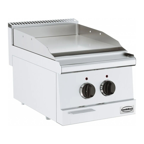
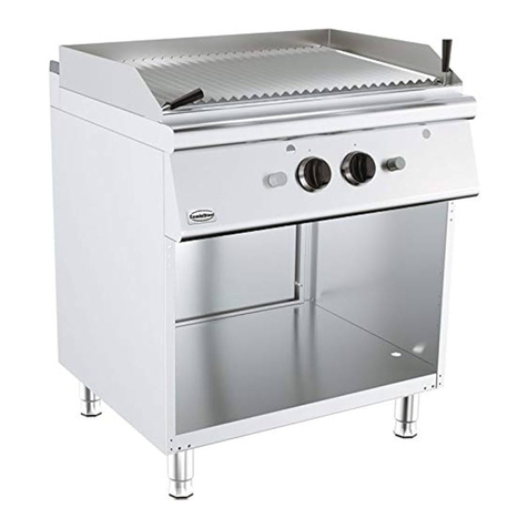
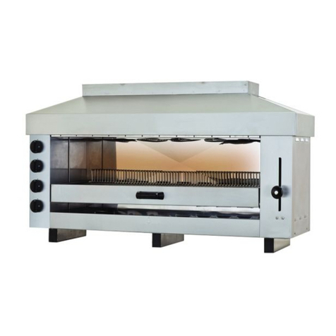
CombiSteel 7478.0110 User manual

1/39
7478,0110, 7478,0520
7478.0420, 7478.0422
GGL721
LAVA CHAR GRILL
INSTRUCTION MANUAL

2/39
CONTENTS
INSTALLATION INFORMATION
A. AIMS AND SCOPE
B. RESPONSIBLITIES
C. SIGNS
1. DEVICE SPECIFICATIONS
1.1. TECHNICAL SPECIFICATIONS
2. TRANSPORTATION AND INSTALLATION OF THE PRODUCT
3. SAFETY WARNINGS
4. COMING THINGS TOGETHER WITH THE PRODUCT
5. DEVICE DESCRIPTION/EXPLANATION
6. PLACING THE DEVICE AND PREPARING IT FOR START UP
7. PRE-INSPECTIONS TO BE PERFORMED FOR START UP
8. START UP
9. GAS CONTROL
10. GAS DIAGRAM
11. GAS EQUIPMENTS
12. CLEANING THE DEVICE
14. SAFE LIFE
15. CHANGE THE GAS ENJECTOR

3/39
A. AIMS AND SCOPE
Descriptions for safe use and maintenance of the product
B. RESPONSIBLITIES
Responsibilities of Product’s Owner: The product’s owner is responsible for applying of safety rules stated in this Instruction Manual or
getting them applied by delegating his authorities and risks, which may arise due to not applying. The product’s owner is also responsible
for the periodical maintenance of the machine.
Responsibilities of the Manufacturers: The manufacturer is responsible for the risks due to manufacturing and assembling faults, even
though all requirements stated in this manual have been fulfilled.
C. SIGNS
WARNING: This sign indicates that it must be complied with the instructions related to the subject; otherwise, the risky
conditions, in which there can occur some damages and dangers
CAUTION: This sign indicates any risky conditions, which can cause damages in material and injuring of people, provided
that one does not pay attention and states that one must be careful.
DANGER: This sign indicates high risky conditions in which people can be injured, provided that one does not pay attention
and the rules always to be complied with.
DANGER: This sign indicates high risky conditions in which the people can be injured or can die due to electrical shock.
Equipotential connection terminal
(If necessary, it must be connected to other equipment to make equal the potential)

4/39
1. Device Specifications
1.1 Technical Specifications

5/39
7478.0420

6/39
Heat input of one burner
Total heat input
Type
Number of nozzles
G20-
20mbar
G20-
25mbar
G30-
30mbar
G30-
50mbar
G31-
37mbar
7478,0110
2
4,8
4,8
4,8
4,8
4,8
9,6
9,6
9,6
9,6
9,6
7478,0520
7478.0420
1
6
6
6
6
6
GGL721
7478.0422
2
12
12
12
12
12
Nozzle Diamater
Type
Nozzle diamter
G20-
20mbar
G20-
25mbar
G30-
30mbar
G30-
50mbar
G31-
37mbar
7478,0110
7478.0520/GGL721/7478.0420/7478.0422
Burner
1,90
1,90
1.10
1.00
1.10
Pilot Burner
0,5
0,5
0,25
0,25
0,25
Burner
1,90
1,90
1.20
1.00
1.20
Pilot Burner
0,5
0,5
0,25
0,25
0,25
7478.0422

7/39
2. TRANSPORTATION AND INSTALLATION OF THE PRODUCT
During transportation, take necessary precautions against the risk of falling down and being turned upside down for the
product.
Place the product onto a flat and solid ground.
Do not install the product near the flammable and explosive materials and do not keep any flammable and explosive
material near the furnace, while it is working.
Keep surely a fire extinguisher near the furnace and check whether the periodical checking of the fire extinguisher has
been implemented or not.
3. SAFETY WARNINGS
It is deemed that the users have accepted to conform to the rules stated in instruction manuals and their products will be out of
guarantee scope, unless they conform these rules.
The users are responsible for every sort of abstract and tangible cases, which can arise in case of not conforming to the rules stated
instruction manual.
Do not put any living on the devices. Device must be used to the purpose.
The children and unauthorized people are not allowed to use the device.
While the device is working, do not open in any way the cover of the device with cover.
Be careful not to squeeze your hands while closing the covers.
The device and covers should not be treated as step or ladder in any case.
During cleaning, do not use scratching and abrading means.
All safety checking has been performed. All tests have been implemented related to the product and the product is in active.
Use rubber gloves during cleaning and maintenance.
Do not remove the label of the devices and warning labels
Manufacturer firm is not responsible for the printing errors, which take place in the instruction manual and device description catalogue,
coming together with the device.
Manufacturer reserves the right to make changes related to the every kind of improvement, if it is necessary.
The regulations of the device except for the control can only be performed by the unhorsed services. Do not be involved in the device
adjustments.
Gas Type
Gas
Category
Gas supply
pressure mbar
Country of destination
I2E
20
DE,LU,PL.RO
I2E+
20/25
BE,FR
I3B/P
50
AT,DE,HU
I3+
28-30/37
BE,CH.CY,CZ,EE,ES,FR,GB,GR.IE,IT,LT,LV,PT,SI,SK
I I 2E3B/P
20/50
DE
I I 2E+3+
20/25,28-30/37
BE,FR
I2H
20
AT,CH,CZ,DK,EE,ES,FI,GB,GR,IE,IT,LT,LV,NO,PT,SE,SI,SK,RO,BG,TR
I3B/P
28-30
CY,CZ,DK,EE,FI,GR,HU,IT,LT,LV,MT,NL,NO,SE,SI,SK,RO,BG,TR
I I 2H3B/P
20,28-30
CZ,DK,EE,FI,GR,IT,LT,LV,NO,SE,SI,SK,RO,BG,TR

8/39
In case of needing to drive the device by a different gas, this transformation must be carried out a certified specialist or an authorized
service.
When determining any gas leakage, gas valve must be closed and burning must be ended up.
This appliance is only for professional use and that it shall be used by qualified people
If the fire stops continuously, authorized service must be called.
It is necessary to call an authorized service for installing the device, and if necessary, for changing in order to use it with other gases.
The information about gas installation has been given in instruction manual.
Gas adjustments can only be changed by your authorized service. Do not be involved in the adjustments.
Qualified installer should be called in to install the appliance and, if necessary, to convert it for use with other gases, in keeping with
currently installation regulations in country in whıch the apliance is to be installled.
4. COMING THINGS TOGETHER WITH THE PRODUCT
A. Description Catalogue
B. User/Maintenance/Assembling Manual
C. Guarantee Document
5. DEVICE DESCRIPTION/EXPLANATION
The device have wholly manufactured regarding to hygienic standards.
The legs are in adjustable feature and manufactured by stainless steel material.
For the insulation purposes, glass- wool and stone–wool have been used. Thanks to this application, wasting of energy can be able to
prevent.
It can work by LPG or natural gas.
Burner has safety valve and thermocouple. If the fire puts off, gas flow stops.
6. PLACING THE DEVICE AND PREPARING IT FOR START UP
While the devices are in operation, do not keep burning material (plastic bags, table napkin, clothe etc.) near them.
Read the instruction and maintenance manual absolutely.
Open the packing of the device and remove all protective tapes.
Opening the cover of the device, take out the instruction manual and guarantee document.
Place on the ground the machine with adjustable leg in type by adjusting its legs, for fixed the devices with fixed leg, by smoothing the
ground.
There must be sufficient ventilation in the area, where you operate the device.
Place your device 10 cm away from the surfaces not heat resistant and the wall.
7. PRE-INSPECTIONS TO BE PERFORMED FOR START UP
Be sure that appropriate gas is used.
Be sure that there isn’t any leakage on the gas connection of the device.
Read the instruction manual absolutely
8. START UP
On the figures in gas control section, the figures of control panels existing on the device have been shown. According to these figures,
check whether or not gas connection have been made exactly and correctly, as mentioned earlier.
Because Control switches existing on the device are graded, we can provide any cooking in power we desire. (FIGURE 2

9/39
9. GAS CONTROL
C
B
A
Figure 3
A- PINPOINT FLAME
B- FULL FLAME
C- HALF FLAME
IGNITION OF THE PILOT BURNER
Press the knob and turn it counterclokwise until it reach position .Wait 20 seconds all the air expelled from the pipes then push
piezoelectric button until the pilotflame alights.After 5 seconds release the konb desired position.Repeat oparation if the pilotflame should go
out.
IGNITION OF THE BURNER
Turn to knob desired flame level ;the gas will fallow the main burners,which will ignated.
10. GAS DIAGRAM
07
17
18
10-01
10-02
01-03
01-02
13
14
09
08
19
20
06
05
04
10
11
10-03
16
15
12
01-01
01
03
02
0

10/39
11. GAS EQUIPMENTS
NO
PART NAME
DIMENTION/
STANDART
01
Pilot Burner
02
Burner
4,8 kW
03
Collector
Ø21x2 1000mm
05
Nut
M16x10
06
Olive
Ø 10 (İnlet)
08
Olive
3/8’’ (Outlet)
07
Gas valve
ECA 703883112
09
Pipe
Ø4
10
Ünion
Ø 10
10-01
Olive
3/8’’
10-02
Nut
Ø 10
11
Nozzle
M8
12
Pipe
Pilot burner pipe
13
Olive
Ø4
14
Nut
Ø4
15
Termocouple
M9x1000
16
Piezoelectric
17
İgnition cable
2.5 mm
18
Knob
19
label
2.5mm²x200mm
12. CLEANING THE DEVICE
Device must be cleaned every day after use, after being sure that it is completely cooled down.
Cleaning must be made by a clean wet cloth by wiping the device. It is recommended that stainless steel surfaces should be wiped by
inox cleaners.
During cleaning, do not use sharp edged, cutting and drilling tools such as scraper, emery in no way.
Cleaning must not be done by spraying the water onto the device in no way.
13. INTERVENTION AFTER FAILURE
FAILURES / CAUSES
There is no cooking.
Be sure that the gas connection to the device has been made and there is gas flow to the device.
Be sure that you have opened the right control valve.
Be sure that you have fired up pilot fire.

11/39
14. SAFE LIFE
The safe life of the product is 10 years.
15. CHANGE THE GAS ENJECTOR
15.1 Main Burner
1) Remove the control panel by unscrew the secrews ‘2’.
2
2)Raplace the main burner nozzles with disered gas type nozzle according to nozzle daimeter chart.
Main
burner
nozzle

12/39
Primary air
a
-adjustment of the diffuser for gas types
G20-20 mbar:a=15 mm G20-25 mbar:a=15mm
G30-30 mbar:a=15 mm G30-50 mbar:a=12 mm
G31-37 mbar:a=12 mm
15.2 Pilot Burner
The pilot flame is the nozzle type with fixed air.The only adjustment required is replacement of the nozzle depending on the type of gas.
01-03
01-02
01-01
- Lossen the taper nut (01-01) remove the taper (01-02) and pilot nozzle (01-03)
- Replace the pilot nozzle with desired gas type nozzle according to nozzle chart.
- After replacing the pilot nozzle place the taper and tighten the taper nut.

13/39
7478,0110, 7478,0520
7478.0420, 7478.0422
GGL721
LAVAKOHLENGRILL
BEDIENUNGS- UND WARTUNGSANLEITUNG

14/39
INHALT
A. ZWECK UND UMFANG
B. AUFGABEN
C. SYMBOLE
1. GERÄTEIGENSCHAFTEN
1.1 TECHNISCHE EIGENSCHAFTEN
2. TRANSPORT UND INSTALLATION DES PRODUKTS
3. SICHERHEITSWARNUNGEN
4. MIT DEM PRODUKT ZUSAMMEN GELIEFERTES ZUBEHÖR
5. GERÄTBESCHREIBUNG / ERKLÄRUNGEN
6. INSTALLATION DES GERÄTS UND VORBEREITUNG ZUR INBETRIEBNAHME
7. VORBEREITUNG ZUR INBETRIEBNAHME
8. INBETRIEBNAHME
9. GASKONTROLLE
10. GASSCHEMA
11.GASAUSTATTUNGEN
12. REINIGUNG DES GERÄTS
13. WAS IM STÖRFALL ZU TUN IST
SICHERE NUTZUNGSDAUER
15.WECHSELN DER GASINJEKTOREN

15/39
1. ZWECK UND UMFANG
Beschreibung der sicheren Anwendung und Wartung des Produkts.
2. AUFGABEN
Verantwortungen des Produktbesitzers: Der Produktbesitzer ist verantwortlich für die Einhaltung der in dieser Gebrauchsanleitung
beschriebenen Regeln, auch falls die Nutzungsrechte übertragen werden, bzw. für die Risiken, die durch die Nicht-Einhaltung dieser
Sicherheitsregeln entstehen können. Er ist auch für die periodischen Wartungen des Produkts verantwortlich.
Verantwortungen des Herstellers: Der Hersteller ist verantwortlich für alle Produktions- und Montagefehler, welche durch die in dieser
Anleitung beschriebenen Vorgänge entstanden sind.
3. SYMBOLE
WARNUNG: Dieses Symbol weist darauf hin, dass die bezüglich des Themas gegebenen Anweisungen eingehalten werden
müssen, da sonst ein Risiko besteht, dass Schäden und Gefahren entstehen können.
ACHTUNG: Dieses Symbol weist darauf hin, dass bei Unachtsamkeit das Risiko besteht, dass Personen verletzt oder Material
beschädigt werden kann. Es weist darauf hin, dass Vorsicht angebracht ist.
GEFAHR: Dieses Symbol weist darauf hin, dass eine erhöhte Verletzungsgefahr für Personen besteht. Es weist auf
Anweisungen hin, die unbedingt eingehalten werden müssen.
GEFAHR: Dieses Symbol weist darauf hin, dass eine erhöhte Gefahr besteht, dass Personen infolge von Stromschlägen
verletzt werden und sterben könnten.
ISOELEKTRISCHE ANSCHLUSSKLEMMEN: Dieses Symbol weist darauf hin, dass nebeneinander benutzte Geräte miteinander
geerdet werden müssen.

16/39
1. GERÄTEIGENSCHAFTEN
1.1 TECHNISCHE EIGENSCHAFTEN

17/39
7478.0420

18/39
Wärmezufuhr des Brenners
Gesamte Wärmezufuhr
Typ
Anzahl der Düsen
G20-
20mbar
G20-
25mbar
G30-
30mbar
G30-
50mbar
G31-
37mbar
7478,0110
2
4,8
4,8
4,8
4,8
4,8
9,6
9,6
9,6
9,6
9,6
7478,0520
7478.0420
1
6
6
6
6
6
GGL721
7478.0422
2
6
6
6
6
6
12
12
12
12
12
Düsendiameter
Typ
Düsendiameter
G20-
20mbar
G20-
25mbar
G30-
30mbar
G30-
50mbar
G31-
37mbar
7478,0110
Brenner
1,9
1,9
1.10
1.00
1.10
Pilotbrenner
0,5
0,5
0,25
0,25
0,25
7478,0520/7478.0420/7478.0422/GGL721
Brenner
1,9
1,9
1.20
1.00
1.20
Pilotbrenner
0,5
0,5
0,25
0,25
0,25
7478.0422

19/39
2. TRANSPORT UND INSTALLATION DES PRODUKTS
Treffen Sie während des Transports des Produkts die nötigen Vorkehrungen, die ein Fallen und Kippen verhindern.
Stellen Sie Ihr Produkt auf einen geraden, stabilen Untergrund.
Installieren Sie das Produkt nicht neben brennbaren und explosiven Materialien und deponieren Sie keine brennbaren und
explosiven Materialien neben dem Ofen, während er in Betrieb ist.
Lagern Sie unbedingt einen Feuerlöscher in der Nähe des Produkts. Und kontrollieren Sie, dass die periodischen
Wartungen des Ofens durchgeführt wurden.
3. ALLGEMEINE REGELUNGEN UND WARNUNGEN (SICHERHEITSWARNUNGEN)
Die Benutzer akzeptieren im Voraus, dass sie die in der Bedienungsanleitung festgelegten Bestimmungen einhalten, ansonsten dass das
Gerät AUßER GARANTI ist.
Die Benutzer akzeptiert auch, dass die begrenzte Garantieverantwortungsangaben bekannt gegeben sind.
Auf den Geräten sollen es keine lebenden oder leblosen Substanzen gelegt werden. Keine Lebewesen sollen in die Geräte gelegt werden.
Kindern und Personen, die nicht befugt sind, darf nicht erlaubt und ermöglicht werden, die Geräte zu benutzen.
Bei Geräten mit Klappe darf die Klappe auf keinen Fall geöffnet werden, während das Gerät in Betrieb ist.
Wenn Sie die Klappe des Geräts schließen, achten Sie darauf, Ihre Hand nicht einzuklemmen.
Die Geräte und ihre Klappen dürfen nicht als Leiter oder Stütze benutzt werden.
Während der Reinigung dürfen keine kratzenden oder schabenden Geräte benutzt werden.
Diese Bedienungsanleitung bestätigt, dass die Sicherheitskontrollen aller Geräte durchgeführt, völlig getestet und in gutem Zustand
Funktionsfähig sind.Benutzen Sie Handschuhe ausKunststoff während der Reinigung.
Entfernen Sie die Etiketten und Paneele der Geräte nicht.
Der Hersteller ist nicht verantwortlich für die Druckfehler in der Bedienungsanleitung und Einleitungsbochure des Geräts.
Der Hersteller ist frei nötige oder für den Benutzer oder für sich nützliche Änderungen der Herstellung zu machen.
Die Einstellungen durch unsere Firma, können nur vom zuständigen Service geändert werden.
Für die Montage des Geräts und falls es nötig wird, soll ein fachkundiger Installateur für die Umwandlung mit den Gasen gerufen
werden.
Falls eine Gas-Leckage festgestellt wird, soll das Gasventil und Brennung geschlossen werden.
Das Gerät ist für die professionelle Anwendung und soll vom qualifiziertem Personal benutzt werden.
Gastyp
Gaskatergorie
Gasfufuhr Druck
mbar
Herrkunftsland
I2E
20
DE,LU,PL.RO
I2E+
20/25
BE,FR
I3B/P
50
AT,DE,HU
I3+
28-30/37
BE,CH.CY,CZ,EE,ES,FR,GB,GR.IE,IT,LT,LV,PT,SI,SK
I I 2E3B/P
20/50
DE
I I 2E+3+
20/25,28-30/37
BE,FR
I2H
20
AT,CH,CZ,DK,EE,ES,FI,GB,GR,IE,IT,LT,LV,NO,PT,SE,SI,SK,RO,BG,TR
I3B/P
28-30
CY,CZ,DK,EE,FI,GR,HU,IT,LT,LV,MT,NL,NO,SE,SI,SK,RO,BG,TR
I I 2H3B/P
20,28-30
CZ,DK,EE,FI,GR,IT,LT,LV,NO,SE,SI,SK,RO,BG,TR

20/39
Falls es häufige Unterbrechungen gibt, soll der zuständige Service gerufen werden.
Die Gasinstallation ist in der Bedienungsanleitung beschrieben. Die Teile, deren Gebrauchsdauer beendet sind, sollen von unserem
zuständigen Service gewechselt werden.
Der Gasanschluss ist in der Bedienungsanleitung beschrieben.
Die Gaseinstellungen werden von unserem Service gemacht. Bitte ändern Sie die Einstellungen nicht.
Falls das benutzte Gas geändert wird, sollen die Einstellungen vom Service gemacht werden.
4. MIT DEM PRODUKT ZUSAMMEN GELIEFERTES ZUBEHÖR
A. Broschüre
B. Betriebs-/Wartungs-/Montageanleitung
5. GERÄTBESCHREIBUNG / ERKLÄRUNGEN
Die Geräte wurden unter Kenntnisnahme der Hygiene-Standards hergestellt.
Alle Zubehörteile, deren Außen- und Innenseiten und Oberflächen, die mit dem Lebensmittel in Berührung sind, wurden aus AISI 304(Cr-Ni
18/10) Edelstahl hergestellt.
Die Beine sind einstellbar und aus Edelstahl hergestellt.
Bei der Isolation wird İZOCAM Steinwolle benutzt. Durch diese Vorgehensweise wird eine Energieverschwendung verhindert.
Der Körpe und die Paneelen sind aus AISI304 (Cr-Ni 18/10) Edelstahl.
Kann mit Flüssiggas betrieben werden.
Der Brenner ist mit elektrischer Zündung, Sicherheitsventil und Thermokupplung ausgestattet. Wenn die Flamme ausgeht, wird das Gas
gesperrt.
INSTALLATION DES GERÄTS UND VORBEREITUNG ZUR INBETRIEBNAHME
Halten Sie die brennbaren Materialien fern, wenn das Gerät betrieben wird.
Lesen Sie die Bedienungs- und Montageanleitung vorsichtig durch.
Öffnen Sie die Verpackung des Geräts. Entfernen Sie alle Schutzstreifen.
Öffnen Sie die Klappe des Geräts und nehmen Sie die Einleitungs,- Bedienungs,- Instandhaltungs,- Reparatur- und Montageanleitung
heraus.
Stellen Sie die einstellbaren Beine ein, falls die Beine nicht einstellbar sind, ebnen Sie den Boden, bevor Sie das Gerät aufstellen.
Btreiben Sie das Gerät nicht in Räumen, in denen keine ausreichende Ventilation gibt.
Stellen Sie sicher, dass geeigneter Druck in das Gerät kommt. Dieser Druck soll für Gase der Klasse G20 (lpg) 17-25 mbar, für Gase der
Klasse G30 (Erdgas) zwischen 20-35 mbar und 25-45 mbar. Betreiben Sie auf höheren und unteren Druckwerten Ihr Gerät nicht..
Stellen Sie die Oberflächen des Geräts, die nicht der Wärme beständig sind mindestens 5 CM fern.
7. VORKONTROLLEN FÜR DAS BETÄTIGEN DES GERÄTS
Stellen Sie sicher, dass Sie geeignets Gas für die Zufuhr benutzen.
Stellen Sie sicher, dass es keine Gas-Leackage gibt.
Lesen Sie unbedingt die Gebrauchs- und Wartungsanleitung durch.
8. INBETRIEBNAHME
Die Kontrolpaneele sind im Abschnitt der Anhänge gezeigt worden. Laut diesen Zeichnungen, ist das Gerät, dessen Gasverbindungen
vorher ganz und richtig gemacht wurde, bereit für die Nutzung.
Achten Sie auf Drehung des richtigen Kontrollschalters.
This manual suits for next models
4
Table of contents
Languages:
Other CombiSteel Grill manuals