Comdronic AC6-SP User manual

1
Electronic Commissioning Unit
Instructions
1. The Comdronic AC6 Electronic Commissioning Unit
2. Health and Safety
3. Description of Unit
4. Connection and Set-up Procedure
5. Menu System
a. Main Menu
b. Units Menu
c. Display Menu
d. Damping Menu
e. Advanced Menu
6. ‘Quick Valve’ Storing Function
7. PcomPRO Project Application Software
8. Spares and Accessories
9. Technical Specification
10. Statement of Conformity
11. Contact Us
12. Glycol/Water SG Chart
1. The Comdronic AC6 Electronic Commissioning Unit
The Comdronic AC6 electronic commissioning unit has been developed in response to demand
from discerning commissioning engineers requiring an improvement in measuring techniques for
differential pressures in heating and air conditioning systems.
The Comdronic AC6 unit utilises state-of-the-art technologies in the field of electronics, software and
hydraulic protection for the sensitive measuring element.

2
2. Health and Safety
Comdronic Ltd takes every reasonable precaution to ensure that AC6 commissioning units
are designed, constructed, calibrated and tested for safe and trouble-free operation when
used in accordance with the operating instructions.
For safe operation, it is important that commissioning engineers read and understand the
instructions contained within this manual. It is also very important that those employed in
the function of commissioning are aware of the general hazards associated with the systems
being commissioned.
When working with the AC6, it is the user’s responsibility to ensure that any Personal
Protective Equipment (PPE) or clothing is worn as appropriate to the hazards potentially
present.
It is also the user’s responsibility to understand the Health and Safety issues relating to high
pressure systems, high temperature systems and systems containing flushing agents,
cleaning agents and/or antifreeze agents. This list is, however, not exhaustive.
Please note: whilst every effort is made to ensure that valve data is correct, Comdronic Ltd
cannot be held responsible for modifications, updates and new product additions. Valve
manufacturers invariably reserve the right to modify their products without notice and, as
such, delays in updating the Comdronic™ software may result. The user is advised to check
performance data (Kvs values) of specific valves prior to use.
3. Description of Unit
The Comdronic AC6 Unit comprises the following:
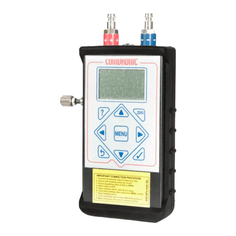
Hand-held electronic manometer, enclosed in a removable rubber protector.
Quick-connect tubing set, complete with manually operated isolation valves.
A variety of adapters to connect to the majority of currently manufactured balancing valves.
Toolkit.
Lanyard for attachment of the unit to pipework etc.
Spare battery.
Instruction Manual
Quick Start Guide and Menu Map.
All above incorporated in a lightweight carrycase.

3
4. Connection and Set-up Procedure
For immediate operation of the unit, please refer to the Quick Start Guide.
Press the MENU button to switch the unit on.
Use the button for cancelling entries or for returning to previous screens. The button also
allows the unit to be switched off.
Use the MENU button to show the display options.
Press ?at any time for context-sensitive help files. Use the ▲▼buttons to scroll through help
files.
System Defaults
The AC6 unit has been set up with default values for all the editable functions as follows:
Language = English
Pressure = kPa
Flow = l/s
Design Flow = 0 l/s
Target Flow = 0%
Flow Alerts = Disabled
Back Light Timer = 5 minutes
Auto-off Timer = 5 minutes
Update Time = 1 second
Sample Time = 3 seconds
Specific Gravity = 1.0
Details of how to change these settings are provided later in this manual.
Automatic Alerts
In addition to the menu options which can be selected by the user, there are a series of automatic
functions which will be displayed on the message bar at the top of the screen. These include:
Zero Sensor
Low Battery
Change Battery
Specific Gravity (displays when not set to 1.0sg)
Temperature Warning (when internal temperature is high)

4
Connection
Select the correct connection adaptors for the device being measured.
Attach adaptors to the connection tubes before attachment to the valve or measuring device.
Each connection tube is fitted with an isolating valve and it is a matter of personal preference
whether the hoses are used with the isolating valves adjacent to the AC6 unit or adjacent to the
subject measuring device.
1 Before starting, please ensure that:
oNeither tube is connected to the AC6, and
oBoth isolating valves on the connection tubes are in the CLOSED position.
2 Attach the red plastic connection tube to the high-pressure test point on the subject
measuring valve or device.
3 Attach the blue plastic connection tube to the low-pressure test point on the subject
measuring device.
4 Ensure that the equalising valve on the AC6 is OPEN (turn anti-clockwise) and then attach
the AC6 unit to the free ends of the red and blue connection tubes.
5 Open the isolating valves on the red and blue connection tubes. The differential pressure
across the subject measuring device will generate flow through the connection tubes from
the high-pressure side to the low-pressure side – thus expelling the air from the tubes.
6 Close the isolating valves on both the red and blue connection tubes.
7 Press the ZERO button to set datum at zero.
8 Open the isolating valves on both the red and blue connection tubes.
9 Close the equalising valve.
10 The unit will now read differential pressure.
Notes:
1 When extremes of temperature change are apparent i.e. when used on a hot system or if
the instrument is transferred from a warm environment to a cold environment, it may be
necessary to zero the AC6 unit after a period of time has elapsed and the unit has
stabilised.
2 The Auto-off Timer will switch the unit off after a defined period of inactivity.
IMPORTANT SAFETY NOTE:
For safe removal of the AC6 unit, ensure that the equalising valve is OPEN before CLOSING
the isolating valves on connection tubes. The AC6 unit and the connecting tubes can now be
removed safely from the subject measuring valve or device.

5
5. Menu System
The AC6 has been designed with 5 menus for ease of use. Each AC6 is supplied with a ‘Quick Start
Guide’ which shows the layout of each menu.
Main Menu Units Menu Display Menu Damping Menu Advanced Menu
Select Valve Pressure Flow/Pressure Update Time Flow Alerts
Valve Position Flow Multi Display Sample Time Back Light Timer
Design Flow Pressure Auto Off Timer
Target Flow About View Size As
Pipe Size
User Kvs
Change SG
The menu system is accessed using a single press of the MENU button. Each menu can then be
selected by using the ◄► keys. When the correct menu is shown on the screen, use the ▲▼
keys to select the correct function which is then accepted using the button.
Press the MENU button twice for language options. Language options apply to Menus and Help
screens only.
Menu functions that require a numeric value to be added use a system which is best described
using the following example:
Example- Setting the design flow to 1.05 l/s.
MENU selects the Main Menu option
▼▼ moves the cursor down to the Design Flow option
accepts the Design Flow option
▲will change the value of the first column to 1
►selects the next column
▼selects a decimal point
►selects the next column
▲▲▲▲▲,changes the digit to 5
accepts the selected value of 1.05
returns to the main display
To enter a negative number, use the ZERO key before any number is added.
To enter a decimal point, use the ▼arrow when the zero digit is showing.

6
5a. Main Menu
Within the Main Menu there are 7 functions
Select Valve
To select the manufacturer, use the ◄► keys.
To select the type of valve, cat no. and size, use the ▲▼ keys followed by the ◄► keys for
individual selections.
Important: Select all items on screen before using button to accept.
Valve Position
This must be entered when variable orifice valves are being measured.
The handwheel position for variable orifice valves is required so that the correct value of Kvs is used
for the derivation of the flowrate. This screen allows the position to be edited.
The display shows the maximum and minimum recommended positions for the valve. The minimum
position shown ensures that the valve maintains reasonable accuracy.
MAIN
SELECT VALVE
VALVE POSITION
DESIGN FLOW
TARGET FLOW
PIPE SIZE
USER Kvs
CHANGE SG
Valve make
r
Fixed
Cat No.
Size
0
x = 4
Min = 1 Max = 4
Edit box.
Minimum and
maximum usable
settings.
Current setting.
Press
to retain.

7
Design Flow
The design flow for the selected valve can be edited in this screen.
When a value is entered, the actual flow will be calculated as a percentage of the design flow and
will be displayed on the Multi Display in the design flow box. Design flow can be entered in any of
the units selectable in the Units Menu.
Target Flow
The target flow for the selected valve can be edited in this screen.
When a value is entered it will be displayed on the main display in the target flow box.
Target flow must be entered as a percentage and is generally derived when carrying out
proportional balancing. Typically, the value used will be the same as the calculated design flow
percentage on the index circuit.
Balancing to 100% target on subsequent valves will ensure that valves adjacent to the index valve
are balanced.
0
x = 10 L/S
Enter design flow
Current setting.
Press
to retain.
0
x = 94%
Enter Target flow
Edit box.
Edit box.
Current setting.
Press
to retain.

8
Pipe Size
Pipe size is entered if the user wishes to use the meter to establish the velocity in the pipe. To
display velocity, choose a velocity unit from the Units Menu.
User Kvs
This screen allows for the user to enter the Kvs value of a measuring device that is not held in the
database of valves. Typically this would be a fixed orifice device. When a Kvs is required for a
variable orifice device, the Kvs is required for each position of the handwheel.
Change SG (Specific Gravity)
This screen allows the user to enter the value of the SG (see Chapter 12). Typically this would be
used when glycol or other antifreeze agents are used in the system.
Note: When an SG is set to a value other than 1.0, an advisory note is added to the top of the
display.
0
x = 4 Kvs
Enter user Kvs
Current setting.
Press
to retain.
Edit box.
0
Enter SG
x = 1.0
Current setting.
Press
to retain.
Edit box.
Current setting.
Press
to retain.
Edit box.
0
x = 0 mm
Enter Pipe size

9
5b. Units Menu
This screen gives the user the option of selecting the preferred units for display on the AC6.
Use ▲▼ keys to select option followed by the button to accept.
Pressure
This screen will display differential pressure units. The ►button will change the displayed units to
kPa, psi, bar, cmH2O, IWGA (inches water gauge), Ft HD (feet head) or Pa. Use the button to
accept.
Flow
This screen will display volume flow units. The ►button will change the units through l/s, l/m, l/h,
USGPM, UKGPM, m3/h, m3/m, m3/s. Use the button to accept.
UNITS
PRESSURE
FLOW
kPa
0.00
Pa
1000
Select D.P Unit
Conversion factor
from base unit. Edit box.
L/S
0.00
L/S X 1
Select Flow Unit
Conversion factor
from base unit.
Edit box.

10
Note: Velocity units are available (Metres per second and Feet per second)
In order to display the current velocity in the system being measured it will be necessary to select
the following:
1 – The valve being measured (Main Menu >> Select Valve)
2 – The pipe size (Main Menu >> Pipe Size)
3 – The velocity units (Units Menu >> Flow)
Use ▲▼ keys to select option followed by the button to accept.
5c. Display Menu
The Display Menu has four options:
Flow/Pressure Display when a Fixed / Variable Orifice Valve is Selected
The Flow/Pressure Display is designed for most general commissioning purposes.
The type of valve selected (Fixed or Variable) is shown as a schematic symbol along with
handwheel and Kvs data.
The differential pressure and flow are displayed and continuously updated according to the signals
being received from the valve being measured.
DISPLAY
FLOW/PRESSURE
MULTI DISPLAY
PRESSURE
A
BOUT
Valve being
measured.
This message
scrolls across
screen.
Kvs of valve
bein
g
measured.
Reminder for user to
zero unit at start up.
Schematic for valve
type.
FODRV shown.
Differential pressure
being measured by
AC6.
Flow calculated by
AC6 from DP and Kvs
value.
2.2 Kvs
5.3 kPa
0.14 L/S
Crane D931 Fixed 15mm
ZERO DP

11
Flow/Pressure Display When an Automatic Balancing Valve is Selected
If the design differential pressure is not met, the message LOW FLOW will be displayed. If the
design differential pressure is met, the message will be FLOW OK.
Multi Display – when a Fixed / Variable Orifice Valve is Selected
For commissioning engineers wishing to carry out commissioning using design and target flow the
Multi Display can be selected. This is the most appropriate display when variable orifice valves are
being measured.
Design flow and target flow are displayed. If the values for these parameters are set to zero, a
series of dashes are displayed.
When variable orifice balancing valves are selected and a design and target flow have been
entered, the Comdronic AC6 unit automatically uses the predictive handwheel position and displays
this above the design or target flow in their respective boxes on the display. When the valve has
been adjusted to the predicted position, use the ◄► keys to adjust the handwheel setting. Note:
The design flow and the target flow could be different values so it is important to use the correct
navigation button.
The predictive process is iterative due to the unknown valve authority in the circuit so it will be
necessary to use this feature more than once.
The measuring valve selected is described in the scrolling bar at the base of the screen.
DESIGN TARGET
103 % 89 %
2.9
4.0
4.0 Kvs
5.3 kPa
0.26 L/S
CRANE Variable D930/DM930 15mm
Handwheel position.
Only shown on
VODRV.
Use the ▲key to manually
ad
j
ust handwheel
p
osition.
Kvs value for
measured valve. This
will change when
handwheel position
changes.
Flow shown as a percentage
of the entered design flow.
Flow shown as a
percentage of the
entered tar
g
et flow.
The ►key will
automatically set
the handwheel
position to suit the
target flow. This is
iterative and will
need 2-3 attempts
to be accurate.
0.210 L/S
ZERO DP
8.48
Flowcon Green ‘0’
LOW FLOW
5.0
0.153 L/S
kPa
Current DP
across valve.
Current flow
status.
Design flow for
this setting.
Current valve
setting.
Selected valve.

12
Multi Display – When an Automatic Balancing Valve is Selected
Unique to the AC6 is the ability to display variables associated with automatic balancing valves. The
valve shown is an externally adjustable type.
The design flow for any automatic flow controller will be achieved if the differential pressure across
the valve reaches the design value. Each automatic balancing valve and each setting for the valve
will possibly have a different design DP. The AC6 database holds the design DP for each
valve/setting. Many of the automatic balancing valves programmed into the AC6 have their actual
characteristic in the data. The level of differential pressure across the valve will determine which
data is used. Generally, with automatic valves there is a slight fall in flow when the DP reaches high
values. This fact is true for most automatic valves but normally the fall in flow is within the stated
tolerance for the valve.
When the AC6 is adjusted to select the correct valve/setting, the design flow is displayed within the
valve image. If the DP is not sufficient to create correct flow conditions, the box above the inlet pipe
to the valve will display an up arrow and a value indicating that the DP will need to be increased to
achieve the design flow. The value displayed is the design DP less the actual DP.
In the event of the actual DP being higher than the design DP, the box will display a down arrow
and a DP value that suggests a reduction in actual DP. On an Index circuit, this would suggest that
the pump speed could be decreased to achieve the correct DP value.
ZERO DP 0.210 L/S
FLOW
LOW
5.0
8.48 kPa
Flowcon Green ‘0’
7.52
0.153 L/S
16.0
Indicates that DP must be
raised to achieve design
flow. Arrow will point down
if pressure can be lowered.
DP required to achieve
desi
g
n flow.
Scrolling arrows
indicate ‘some’ flow.
Arrows will continue to
outlet pipe when
desi
g
n flow achieved.
Design flow for
this setting.
Current
flow status.
Setting Tab shows
current setting. Use ▲to
edit. Not shown if the
valve is fixed setting.
Current DP across valve.
Current valve
selection.
Actual flow for this
setting.

13
Pressure Display
The differential pressure is displayed in large text. This screen is useful for users wishing to use the
AC6 unit as a simple manometer.
About
The About screen gives the unique serial number of the unit plus the firmware version.
5d. Damping Menu
Use the ▲▼ keys to select option followed by button to accept.
COMDRONIC AC6
www.comdronic.co.uk
6.03.200AC6-0123
0.00
kPa
Uni
q
ue Serial No.
Firmware version.
DAMPING
UP-DATE TIME
SAMPLE TIME

14
Up-Date Time
This screen allows the user to change the apparent sensitivity of the AC6.
This value is set by the user to increase or decrease the time delay between each screen update. If
the time is short then the screen updates often. A long update time will give the appearance of a
steadier reading.
Use ▲▼ keys for coarse adjustment and ◄► keys for fine adjustment. A typical setting would be
1 second. Note: Increase this time on an unstable system.
Sample Time
This screen allows the user to change the period over which the readings are averaged.
Use ▲▼ keys for coarse adjustment and ◄► keys for fine adjustment. A typical setting would be
3 seconds.
This value can be edited up to 11 seconds and it represents the base time over which the readings
are taken for the rolling average system.
A typical time of 3 seconds allows a large number of readings to be taken before the mean
calculation is made.
The averaging system continues to use 3 seconds of measured values but on a rolling average
basis.
Increasing the sample time will make the screen appear to update slower but with a more stable
reading.
The sample time is also used as a time base when using the pressure chart display to study the
pressure signal from the device being measured.
1.01 Sec
Up-Date time Sample time
3.0 Sec
Sample time

15
5e. Advanced Menu
Flow Alerts
Flow Alerts can be switched between Enabled and Disabled. The alerts relate to the flow through
the selected valve. High/Low Flow Alerts mean that the measured flow is outside the range normally
expected in the valve.
When working on unstable systems – or systems that have little regulation – the alerts can
sometimes impede commissioning operations.
Back-Light Timer
The Back-Light Timer sets the period of time that the light remains on. Pressing any key will re-
activate it. Setting the light to a short time will preserve battery life.
Use the ▲▼ keys to select option followed by button to accept.
Auto-Off Timer
The Auto off timer sets the time the unit remains on. Setting the time to a short time will preserve
battery life.
Use the ▲▼ keys to select option followed by button to accept.
Enabled
Disabled
High/low flow alerts
Select light on time
1 Min
5 Min
10 Min
Always on
Select auto off time
1 Min
5 Min
10 Min
Always on

16
View Size As
This screen allows the user to select the preferred units for selecting valve size. The default unit is
metric (mm).
Use the ▲▼ keys to select option followed by button to accept.
6. ‘Quick Valve’ Storing Function.
This display allows the user to save the data from the current valve to a project. To use this feature
press the button whilst viewing any of the display screens.
The project can be made up from up to ten groups of valves, each with ten valves. The group
number can be selected using the ▲▼ keys and the valve number can be selected using the
◄► keys.
The MENU button gives the user the option to save or delete. If the screen is black, a valve is
already in the location. However, if the screen is white it is possible to load a valve to this location.
MM
Inches
View size as
MENU
TO EXIT
Group 1 Valve 1
0.00 kPa
0.000 l/s
Group No. - 10
Groups available.
Valve No.-10 valves
per group available.
Use ▲▼ keys to
select group.
Use ◄► keys to
select valve No.
DP and flow data
for selected valve.
Use MENU when group
and valve No. have
been selected.
Group 1 Valve 1
Load
Clea
r
Save
Exit

17
Using the SAVE command will overwrite the location with the current valve data.
The Quick Valve feature allows the user to save the selected valve to a memory location which is
quickly accessible without having to use the ‘Select Valve’ option. The purpose of this is to reduce
time when commissioning a system with, for example, 3 different types of valve. The 3 types of
valve could be saved to the Quick Valve memory including the design flow designated for that valve.
When recalled, the valve will be loaded to the unit including the design flow.
Follow the on-screen instructions to save the current selection or delete the existing saved valve.
An additional use for this feature is the ability for the user to save the commissioned data for up to
100 valves for later reference.
When the data for the selected valve has been saved, the following screen appears. The example
shown is for a variable orifice double-regulating valve (all other valve types have a simpler screen).
When using automatic balancing valves, the procedure for using ‘Quick Valve’ is the same as if
traditional balancing valves but the screen showing saved data is different as shown below.
The above example shows that the actual DP is greater than the design DP therefore the flow
status is displayed as FLOW OK.
Further options for saving valve data are available if PcomPRO Project Application Software is
purchased with the AC6 unit – see Chapter 7.
Group 1 Valve 1
19.23 kPa 0.487 l/s
Crane Variable D930DM930 15mm
DESIGN 244 % TARGET 271 %
DESIGN FLOW TARGET FLOW
0.2 90%
4
Valve saved to
this location.
DP and flow data
currentl
y
saved.
Design flow and
target flow %
currently saved.
Handwheel setting
currently saved.
Design and target
flow currentl
y
set.
Group 1 Valve 1
21.5 kPa 0.210 l/s
Flowcon green ‘0’
FLOW OK
5
16.00 kPa
Group and
valve No.
Selected valve.
Current flow
status.
Design flow.
Actual DP
across valve.
Valve setting.
DP required for
design flow.

18
7. PcomPRO Project Application Software
Further options for saving valve data are available if PcomPRO Project Application Software is
purchased with the AC6 unit. PcomPRO gives the user the option of preparing a project on a PC
prior to commissioning the system. The data from the commissioning process can be saved to the
AC6 for later use.
8. Spares and Accessories
Replacement hose sets.
Binder-style adaptors.
Mechseal-style adaptors.
Industry-standard insertion test points.
Temperature and pressure gauges.
Replacement strainers.
9. Technical Specification
Measurement Range / Accuracy
Model: AC6-SP AC6-HP
Accuracy: +/- 1% of reading or +/- 0.1 kPa,
whichever is greater
+/- 1% of reading or +/- 0.2 kPa,
whichever is greater
Max Allowable
Static Pressure: 10 Bar 20 Bar
Measurement
Range: 0.5 kPa to 200 kPa 2 kPa to 600 kPa
Effective Operating Time
20 hours with standard Alkaline PP3 battery
Calibration
Standard factory calibration is carried out in controlled conditions using calibrators traceable to
National Standards. It is recommended that AC6 units are recalibrated at least once per year. This
recommended period is not fixed. Should the AC6 unit be used on systems with dirty water or a high
concentration of cleaning agents, treatments or the user suspects that readings are not perfect then
recalibrate more often.
Valve Database
The performance characteristics of over 4,500 valves – from 70 manufacturers – are pre-
programmed into the AC6.
Valve data is automatically updated whenever an AC6 meter is serviced by Comdronic Ltd.

19
10. Statement of Conformity
This is to certify that the Comdronic AC6 Electronic Commissioning Unit is manufactured in the EU,
has been calibrated in accordance with standards traceable to national standards and conforms to
the published specification. It is CE marked in accordance with the relevant EC directives.

20
12. Glycol / Water SG Chart
SPECIFIC GRAVITY OF WATER / GLYCOL MIXTURES
Temperature % Glycol Additive
Deg. C 0 10 20 30 40 50 60 70 80 90 100
80 0.991 1.003 1.017 1.026 1.036 1.046 1.054 1.062 1.068
70 0.990 1.000 1.010 1.023 1.034 1.042 1.053 1.062 1.069 1.075
60 0.995 1.007 1.017 1.030 1.041 1.050 1.060 1.070 1.076 1.083
50 1.000 1.013 1.013 1.035 1.048 1.057 1.067 1.077 1.084 1.090
40 0.990 1.004 1.018 1.029 1.042 1.054 1.064 1.074 1.085 1.091 1.098
30 0.996 1.007 1.022 1.034 1.047 1.059 1.070 1.080 1.092 1.099 1.105
20 0.999 1.010 1.026 1.038 1.052 1.065 1.076 1.088 1.099 1.106 1.114
10 1.000 1.013 1.028 1.042 1.056 1.070 1.082 1.094 1.105 1.113 1.120
0 1.000 1.015 1.029 1.045 1.061 1.075 1.088 1.100 1.112 1.120 1.128
-10 1.048 1.065 1.079 1.092 1.107 1.118 1.127 1.135
-20 1.068 1.083 1.097 1.113 1.124 1.133 1.136
-30 1.087 1.100 1.118 1.128 1.137 1.137
-40 1.102 1.122 1.133 1.138 1.138
E&OE
This manual suits for next models
1
Table of contents
Other Comdronic Measuring Instrument manuals