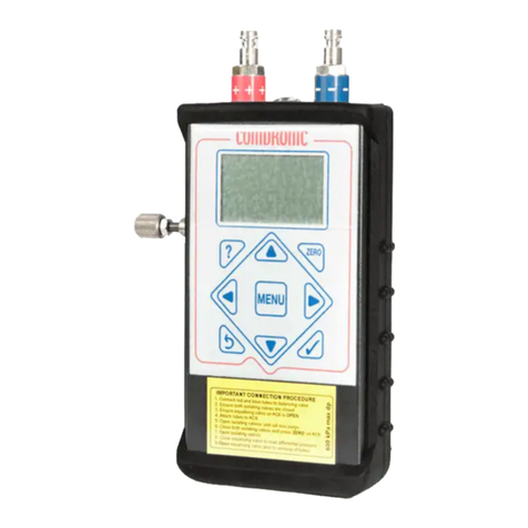
Comdronic AC6 User manual

www.comdronic.co.uk
AC6OperatingInstructions
Contents
HealthandSafety1
StatementofConformity1
MeasurementRange&Accuracy1
ContactUs1
DescriptionofAC62
ConnectionProcedure3
DisconnectionProcedure3
MenuMap4
DisplayMenu5
MainMenu8
UnitsMenu11
DampingMenu12
AdvancedMenu13
Quick‐ValveStoringFunction15
Appendices
Glycol/WaterSpecificGravityChart A1
RecommendedUserMaintenanceProcedures A2

www.comdronic.co.uk

www.comdronic.co.uk
HealthandSafety
Comdronic Ltd takes every reasonableprecaution to ensure that AC6Electronic Commissioning Meters are
designed,constructed,calibratedandtestedforsafeandtrouble‐freeoperationwhenusedinaccordancewith
theseoperatinginstructions.
It is the user’s responsibility to be aware of the general hazards associated with the systems being
commissioned(e.g.highpressures;high/lowtemperatures;thepresenceofflushing/cleaning/antifreeze
agents; etc.) and to use appropriate personal protective equipment / clothing for the hazards potentially
present.
StatementofConformity
This is to certify that the Comdronic AC6 Electronic Commissioning Meter is manufactured in the UK and
conformstothepublishedspecification.ItisCEMarkedinaccordancewiththerelevantEUlegislation.
MeasurementRange&Accuracy
Model: AC6‐SP
(STANDARD‐PRESSURE)
AC6‐HP
(HIGH‐PRESSURE)
Accuracy
(%ofreading):
+/‐1%ofreadingor+/‐0.10kPa
(whicheverisgreater)
+/‐1%ofreadingor+/‐0.20kPa
(whicheverisgreater)
MaxAllowable
StaticPressure: 10bar 20bar
Measurement
Range: 0.5kPato200kPa 1.0kPato600kPa
Factory calibration is carried out, in controlled conditions, using reference equipment which has been
independentlycalibratedtoUKASstandards.
Generally,itisrecommendedthatAC6handsetsareservicedandcalibratedannually–please‘ContactUs’for
further information. However, this is not a fixed period and shorter service intervals may be necessary for
extremelyhigh‐usemetersorformeterswhichare regularlyusedonverydirtysystemsoronsystems that
containhighconcentrationsofcleaningagents/treatments.
Betweenservices,therearesomesimplemaintenanceprocedureswhichcanbe performedtohelp prolong
theaccuracyandperformanceoftheAC6–pleaserefertoAppendixIIforfurtherinformation.
ContactUs
Forallsales,technicalortroubleshootingenquiries:
Tel: +44(0)1473715589
Address: Unit7AlphaTerrace,WestRoad,Ipswich,Suffolk,IP39FD,UK
1

www.comdronic.co.uk
DescriptionofAC6
Press&holdtheMENUbuttontoswitchtheAC6‘ON’.
MENU
?ZERO
Comdronic
- - + +
ConnecttheBLUE
connectiontube
tothisconnector.
Securingring.Usethe
lanyardsuppliedtosuspend
theAC6fromadjacent
pipework(orsimilar)while
takingreadings.
Presstosetazero
datumbeforetakinga
measurement(see
opposite).
Presstoentermenu
screens.
PressMENUagainfor
languageoptions.
Usethe▲ ► ▼ ◄buttons
formenunavigationandto
enternumericaldata.
Presstoaccept
menuselections
andscreenentries.
ConnecttheRED
connectiontube
tothisconnector.
Internalstrainersprotectthe
sensor‐unitfromsmalldirt
particles.Theseareserviceparts.
Note:blockedstrainerswillslow
performanceandreduce
accuracy.
Equalisingvalve.
Presstocancelanentryorto
returntoapreviousscreen.
AlsousetoswitchtheAC6 ‘OFF’.
2
9VBattery
1xAlkaline9VPP3battery.
Batteryaccessatrear.
Typicaleffectiveoperating
time=upto20hours.
ENGLISH
ESPANOL
FRANCAIS
ITALIANO
NORSK
SVENSKA
SelectLanguage
Usethe▲▼ buttonstoselectalanguage.
Presstoaccept.
Key
Throughouttheseinstructions,thereare
twoabbreviationsusedfor‘differential
pressure’asfollows:
Δpisusedinthebodytext.
DPisusedinthescreenimages.
Press?
Buttonon
AC6for
Context‐
Sensitive
Help.

www.comdronic.co.uk
TheAC6handsetissuppliedinalightweightcarrycasewiththefollowingaccessories:
Aremovablerubberprotector.
Apairofconnectiontubes,completewithmanually‐operatedisolationvalves.
Apairofangle‐patternBinder‐styleconnectionadaptorswith3.3mmdiameterneedles.
Apairofstraight‐patternBinder‐styleconnectionadaptorswith2.0mmdiameterneedles.
Asetofhexkeys(3mm,4mm,5mm,6mm&8mm)andascrewdriver.
Alanyardtosuspendthehandsetfrompipeworkwhilstinuse.
Astrainermaintenancekit.
Asparebattery.
OperatingInstructions,aQuick‐StartGuideandaFactoryCalibrationCertificate.
ConnectionProcedure
Note:eachconnectiontubeisfittedwithanisolatingvalveanditisamatterofuser‐preferencewhether
thetubesareusedwiththeisolatingvalvesadjacenttothe
AC6
or,alternatively,adjacenttothesubject
measuringvalve/device.
1.
Selectthecorrectconnectionadaptorsforthevalve/devicebeingmeasuredandattachthemto
theconnectiontubes.
2.
Ensurethatbothisolatingvalvesontheconnectiontubesareinthe
CLOSED
position.
3. AttachtheconnectionadaptorontheREDconnectiontubetothehigh‐pressure(upstream)testpoint
onthesubjectmeasuringvalve/device.
4. AttachtheconnectionadaptorontheBLUEconnectiontubetothelow‐pressure(downstream)test
pointonthesubjectmeasuringvalve/device.
5. EnsurethattheequalisingvalveontheAC6isOPEN.
6. AttachthefreeendsoftheREDandBLUEconnectiontubestothecolour‐codedconnectionpointson
theAC6.
7. OPENtheisolatingvalvesontheconnectiontubestoallowthelinefluidtopurgeanyairfrominside
thetubes.*
8. CLOSEtheisolatingvalvesontheconnectiontubes.
9. FindasafeandstaticpositionfortheAC6.**
10. SwitchtheAC6‘ON’andpresstheZERObuttontosetthedatumatzero.***
11. OPENtheisolatingvalvesontheconnectiontubesandCLOSEtheequalisingvalveontheAC6.
12. TheAC6willnowbereadingΔp.
*
Ifthe
Δp
acrossthevalve/deviceislow,thepurgingprocesswillbeslowduetotheinternalresistance
ofthe
AC6
.
**
The
AC6
is very sensitive and readings will be affected if the position of the handset is moved or
adjustedafter a datum hasbeenset.Alanyardisprovidedand can beusedtosuspend the
AC6
from
adjacentpipework,asappropriate.
***IftheAC6isbeingsubjectedtoanextremechangeoftemperatureatthispoint,thedatummaydriftfrom
zero as the internal temperature of the meter changes and, in these circumstances, it will be necessary to
repeatthisstepuntiltheinternaltemperaturehasstabilisedandazerodatumismaintained.
DisconnectionProcedure
1. OPENtheequalisingvalveontheAC6.
2. CLOSEbothisolatingvalvesontheconnectiontubes.
3. DisconnectthetubesfromboththeAC6andthevalve/device.
3

www.comdronic.co.uk
MenuMap
TheAC6hasfivemenusforeaseofuse:
MAIN
MENU
►UNITS
MENU
►DISPLAY
MENU
►DAMPING
MENU
►ADVANCED
MENU
◄◄◄◄
SelectA
Valve
SelectDP
Units
DPAnd
Flow
Change
Update
Time FlowAlerts
▼▲▼▲▼▲▼▲▼▲
Valve
Setting
SelectFlow
Units Advanced
Change
Sample
Time
Backlight
Timer
▼▲▼▲▼▲
Specific
Gravity
DPOnly
Auto‐off
Timer
▼▲▼▲▼▲
Design
Flow
FlowOnly
On‐Screen
SizeUnits
▼▲▼▲▼▲
Target
Flow%
About
PipeID
▼▲
ChangeKvs
Note: menu options shown in red will require numerical data to be entered and this is achieved using the
buttonsonthekeypad.Thedefaultstartingdigitisalwayszero–thenusethe▲▼buttonsto changethe
value.Usethe►buttontoaddadigitandthe◄buttontoremoveadigit.Ifadecimalpointisrequired,press
the▼buttonwhenthezerodigitisshowing.Toenteranegativenumber,presstheZERObuttonbeforeany
numberisadded.ThefollowingexampleshowshowauserwouldsetaDesignFlowof1.05:
MENUenterstheMainMenu
▼▼▼movesthecursordowntotheDesignFlowoption
acceptstheDesignFlowoption
▲changesthevalueofthefirstcolumnto1
►selectsthenextcolumn
▼selectsadecimalpoint
►selectsthenextcolumn
▲▲▲▲▲changesthedigitto5
acceptstheon‐screenvalueof1.05
returnstothechosendisplayscreen
4

www.comdronic.co.uk
DisplayMenu
TherearefourdifferentdisplayformatsavailablefortheAC6.Themostappropriateformatwilldependonthe
typeofvalve/devicebeingmeasuredandthecommissioningmethodbeingapplied.Thefourdisplayformats
aredescribedbelowbut,first,itisimportanttoexplainsomeautomaticalerts
whichmayappearonanyof
thesescreensasandwhencertaincircumstancesexistasfollows:
*The pressure sensor within the AC6 ceases to compensate for temperature at temperatures above 50°C.
However,aslongaspurgetimesarekepttoaminimum,thetemperature of the fluid within the meter is
usuallyverymuchclosertoambientthanthetemperatureofthelinefluid.Asaconsequence,itisverynormal
fortheAC6tobeusedveryeffectivelyonlowtemperaturehotwatersystems.
The DP And Flow Display is suitable for most general commissioning purposes. Fig. 1 shows an example of
displayed data when a fixed orifice valve has been selected and fig. 2 shows an example of displayed data
whenanautomaticbalancingvalvehasbeenselected.
Fig.1
5
Schematicofthe
selectedvalve.
Kvsofthe
selectedvalve. Detailsofthe
selectedvalve.
DerivedFlow.
CalculatedbytheAC6
usingthemeasuredΔp
andtheKvs.
MeasuredΔp.
5.30
CraneFixedD93115mm
KPa
l
/
s
0.141
Kvs
2.20
ZERODP SG TEMPHIGH
Thissymbolwillshowwhenthe
remainingbatterypowerdrops
below8.0volts.Thisisfor
INFORMATIONONLYasthereis
stillplentyofrun‐timeavailable.
TheZERObuttonwillneedtobe
pressedtosetadatum(see
ConnectionProcedureonpage3)
beforereadingscanbetaken.
SpecificGravityisnot set
to1.0,soreadingsare
currentlybeingauto‐
correctedforSG.
Thetemperatureatthe
sensoristoohighfor
readingstobetemperature‐
compensated.*
Remainingbatterypower
hasdroppedbelow6.5volts
andistoolowfortheAC6
tofunction.Action:FITA
NEWBATTERY.
Thissymbolwillshowwhenthe
remainingbatterypowerdrops
below7.5volts.Action:ensure
thatareplacementbatteryis
on‐hand.
Press?
Buttonon
AC6for
Context‐
Sensitive
Help.

www.comdronic.co.uk
Fig.2
*IfthemeasuredΔpreachesthedesignΔpfortheselectedvalve,theflowstatusmessagewillbeFLOWOK.
However,ifthedesignΔpisnotmettheflowstatusmessagewillbeLOWFLOW.
The Advanced Display can show more complex commissioning data and it may be preferred to the DP And
FlowDisplayifautomaticbalancingvalvesarebeingmeasuredorifasystemofproportionalbalancingisbeing
adopted.Fig.3showsanexampleofdisplayeddatawhenavariableorificevalvehasbeenselectedandfig.4
shows an example of displayed data when an externally adjustable automatic balancing valve has been
selected.
Fig.3
**Theseareiterativeprocessesduetotheunknownvalveauthorityinthecircuitandso2‐3attemptsmaybe
requiredtoachievethedesiredreading.Pleasealsonotethatinconjunctionwithpressingthe◄or►button
ontheAC6,thephysicalhandwheelsettingofthevalvewillalsoneedtobechangedtomatchthenewvalue.
6
Currentcartridge
setting.
Flowstatus
message.*Detailsofthe
selectedvalve.
DerivedFlow.
Measured
Δ
p.
20.48
FlowConGreenGreen.015‐25mm
KPa
l
/
s
0.210
FLOW
OK
l
/
s
0.210
5.00
DesignFlowfor
thisvalveatthis
setting.
Pressthe▲
buttontochange
valvesetting.
Current
handwheelsetting.
Kvsoftheselected
valveatthecurrent
handwheelsetting.
DerivedFlowasa%ofthe
TargetFlow.IfnoTarget
Flowhasbeenentered,
“‐‐‐“isdisplayed.
DerivedFlow.
MeasuredΔp.
5.30
CraneVariableD930/DM93015mm
KPa
l
/
s
0.256
DESIGN
4.00Kvs
4.00
101%
103% TARGET
3.82 3.95
Pressthe▲buttontoMANUALLY
changethehandwheelsettingthat
theAC6isusing.
DerivedFlowasa%ofthe
DesignFlow.IfnoDesign
Flowhasbeenentered,
“‐‐‐“isdisplayed.
Predictivehandwheel
settingtoachievethe
DesignFlow.
Usethe◄buttonto
AUTOMATICALLY
changethe‘Current
HandwheelSetting’
beingusedbytheAC6
tothisvalue.**
Predictivehandwheel
settingtoachievethe
TargetFlow.
Usethe►buttonto
AUTOMATICALLY
changethe‘Current
HandwheelSetting’
beingusedbytheAC6
tothisvalue.**
Press?
Buttonon
AC6for
Context‐
Sensitive
Help.
Press?
Buttonon
AC6for
Context‐
Sensitive
Help.

www.comdronic.co.uk
Fig.4
*The Design Flow for any automatic balancing valve will be achieved if the Δp across the valve reaches (or
exceeds)thedesignvalue.
IftheDesign
Δp
ismet,thedisplayedmessagewillbe
FLOWOK
.
IftheDesign
Δp
isnotmet,thedisplayedmessagewillbe
LOWFLOW
.
TheDPOnlyDisplay(showninfig.5)isthesimplestoptionavailableandmaybepreferredwhentheAC6is
beingusedasasimplemanometer.
Fig.5
The Flow Only Display (shown in fig. 6) would normally only be the preferred display screen when fluid
velocitiesarebeingmeasuredforthepurposesofsystemflushing.
Fig.6
7
Uparrowindicates
thattheΔpmustbe
increasedtoachieve
theDesignFlow.
Approx.
actualflow. DesignFlowforthis
valveatthissetting.
Δprequiredto
achieveDesignFlow. Currentvalve
setting.
FlowConGreenGreen.015‐25mm
LOW
FLOW
0.210 l
/
s
5.00
14.50KPa
0.200 l
/
s
16.00
1.50
Downarrowindicates
thattheΔpis
unnecessarilyhigh.
Measured
Δ
p.
DifferencebetweenMeasured
Δ
pandDesign
Δ
p.
Flowstatus
message.*
Usethe▲buttontoedit
the‘CurrentValveSetting’.
(▲notshownifvalveisafixedsettingtype).
Chevronsintheinlet
pipeindicatethatthe
flowisgreaterthanzero.
Chevronswillshowin
theoutletpipewhen
DesignFlowisachieved.
|KPa
4.27 MeasuredΔp.
Unitsofmeasure.
Kvs=2.3|m/s
1.37 CalculatedFluid
Velocity.
Unitsofmeasure.
16.1mm
InternalPipeDiameter
beingusedtocalculate
thefluidvelocity.
Press?
Buttonon
AC6for
Context‐
Sensitive
Help.
Press?
Buttonon
AC6for
Context‐
Sensitive
Help.
Press?
Buttonon
AC6for
Context‐
Sensitive
Help.

www.comdronic.co.uk
The‘About’menuoption(showninfig.7)givestheuniqueserialnumberoftheAC6(pleasequotethisinany
correspondencewithComdronic)plustheinstalledfirmwareversion.
Fig.7
MainMenu
The Main Menu is concerned with the various selections / parametersthatausermaywishtoenter
dependingonthevalve/devicebeingmeasuredandthecommissioningtechniquesbeingutilised.
The performance characteristics of over 5,000 valves – from 70+manufacturers/brands–arepre‐
programmedintotheAC6andthisdataisautomaticallyupdatedwheneveranAC6isservicedbyComdronic.
Alternatively,itispossibleforuserstoremotelyupdatethevalvedatabaseontheirAC6,usinglatestdatafiles
whichareavailablefromComdronic.Please‘ContactUs’forfurtherinformation.
Note: w
hilst every effort is made to ensure that
storedvalvedataiscorrect,valvemanufacturers
invariablyreservetherightto
modifytheirproducts,withoutnotice,andsoComdroniccannotbeheld
responsibleforanyinaccuraciesor
omissions
.
Fig.8
Make selections for all four parameters (i.e. Manufacturer, Type, Fig. No.&Size) before pressing the
buttontoacceptthem.
8
CRANE
Variable
D902
15mm
Manufacturer/Brand.
ValveType
e.g.Fixed,Variable,
PICV,etc. ValveFig.No.
ValveSize.
Usethe◄►buttons
toscrollthroughthe
availableoptionsfor
eachparameter.
Usethe▲▼buttons
toselectaparameter.
Firmwareversion.
Uniqueserialnumber. AC6‐01236.03.200
COMDRONICAC6
www.comdronic.co.uk
Press?
Buttonon
AC6for
Context‐
Sensitive
Help.

www.comdronic.co.uk
Whenvariableorificevalvesoradjustableautomaticbalancingvalvesarebeingmeasured,thehandwheel
position/cartridgesettingmustbeenteredsothatthecorrect flow data is used forthe
derivation of
flow.
Fig.9
Oncethenewvalueiscorrectonthescreen,pressthebuttontoacceptit.Or,pressthebuttontoexit
thescreenandretainthecurrentsetting.
*Theminimumhandwheelpositionshownensuresthatthevalvemaintainsreasonableaccuracy.
ThismenuoptionallowstheusertoentertheSGofthelinefluid. Typically, this would be necessary when
glycol(orsimilar)ispresentinthesystem.PleaserefertoAppendixIforfurtherinformation.
Fig.10
Oncethenewvalueiscorrectonthescreen,pressthebuttontoacceptit.Or,pressthebuttontoexit
thescreenandretainthecurrentsetting.
Note:whileSGissettoavalueotherthan1.0,“SG”willshowatthetopofthechosendisplayscreenasa
remindertotheuserthatreadingsarebeingsubjectedtoacorrection.Itisstronglyrecommendedthat
usersregularlycheckthatthesetvalueforSGisappropriateforthesystembeingcommissioned.
9
=4
Usethe►button
toaddadigit.
Currentsetting.
Min=1Max=4
2.4
Usethe◄button
toremoveadigit.
Usethe▲▼buttons
toincreaseor
decreaseavalue.
Min.*&Max.
usablesettingsfor
theselectedvalve.
=1
Usethe►button
toaddadigit.
Currentsetting.
EnterSG
1.017
Usethe◄button
toremoveadigit.
Usethe▲▼buttons
toincreaseor
decreaseavalue.
Press?
Buttonon
AC6for
Context‐
Sensitive
Help.
Press?
Buttonon
AC6for
Context‐
Sensitive
Help.

www.comdronic.co.uk
TheDesign Flowfortheselected valvecan beentered/editedin thisscreen. Whenavalue isentered, the
derivedflowwillbecalculatedasapercentageoftheDesignFlowandthiswillbedisplayedontheAdvanced
DisplayintheDesignFlowbox.
Fig.11
Oncethenewvalueiscorrectonthescreen,pressthebuttontoacceptit.Or,pressthebuttontoexit
thescreenandretainthecurrentsetting.
TheTargetFlow%fortheselectedvalvecanbeentered/editedinthisscreen.Whenavalueisentered,itwill
bedisplayedontheAdvancedDisplayintheTargetFlowbox.TargetFlowmustbeenteredasapercentage
andisgenerallyrequiredwhencarryingoutadvancedproportionalbalancing.Typically,thevalueusedwillbe
the same as the calculated Design Flow percentage on the index circuit. Balancing to 100% target on
subsequentvalveswillensurethatvalvesadjacenttotheindexvalveare‘balanced’.
Fig.12
Oncethenewvalueiscorrectonthescreen,pressthebuttontoacceptit.Or,pressthebuttontoexit
thescreenandretainthecurrentsetting.
10
=10.2l/s
Usethe►button
toaddadigit.
Currentsetting.
EnterDesignFlow
10.8
Usethe◄button
toremoveadigit.
Usethe▲▼buttons
toincreaseor
decreaseavalue.
=94%
Usethe►button
toaddadigit.
Currentsetting.
EnterTargetFlow%
97
Usethe◄button
toremoveadigit.
Usethe▲▼buttons
toincreaseor
decreaseavalue.
Press?
Buttonon
AC6for
Context‐
Sensitive
Help.
Press?
Buttonon
AC6for
Context‐
Sensitive
Help.

www.comdronic.co.uk
Ifthevalve/deviceisnotlistedintheAC6’sdatabase,thismenuoptionenablestheusertomanuallyentera
KvsvaluesothataderivedflowcanstillbecalculatedbytheAC6.
Fig.13
Oncethenewvalueiscorrectonthescreen,pressthebuttontoacceptit.Or,pressthebuttontoexit
thescreenandretainthecurrentsetting.
UnitsMenu
Default=kPa
AvailableoptionsarekPa,psi,bar,cmH2O,
IWGA(incheswatergauge),FtHD(feethead)orPa.
Fig.14
Default=l/s
Availableflowoptionsarel/s,l/m,l/h,USGPM,UKGPM,m3/h,m3/morm3/s.
Availablevelocityoptionsarem/sorf/s.
Fig.15
11
=2.2Kvs
Usethe►button
toaddadigit.
Currentsetting.
EnterNew Kvs
2.3
Usethe◄button
toremoveadigit.
Usethe▲▼buttons
toincreaseor
decreaseavalue.
Pax0.000145
Conversion
factorfrom
pascals.
SelectDPUnit
0.0
Decimalplace
formatforthe
selectedunits.
Usethe ◄►buttons
toscrollthroughthe
availableoptions.
Presstoaccept.
PSI
l/sx60
Conversion
factorfrom
litrespersecond.
SelectFlowUnit
0.00
Decimalplace
formatforthe
selectedunits. l/m Usethe ◄►buttons
toscrollthroughthe
availableoptions.
Presstoaccept.
Press?
Buttonon
AC6for
Context‐
Sensitive
Help.
Press?
Buttonon
AC6for
Context‐
Sensitive
Help.
Press?
Buttonon
AC6for
Context‐
Sensitive
Help.

www.comdronic.co.uk
DampingMenu
Default=1.00SEC
ThisscreenallowstheusertoadjusttheapparentsensitivityoftheAC6bychangingthetimedelaybetween
eachscreenupdatefromaminimumvalueof0.1SECtoamaximumvalueof2.55SEC.AlongUpdateTimemay
beadvisableonanunstablesysteminordertogiveasteadierreading.
Fig.16
Oncethenewvalueiscorrectonthescreen,pressthebuttontoacceptit.Or,pressthebuttontoexit
thescreenandretainthecurrentsetting.
Default=3.0SEC
Thisscreenallowstheusertoadjusttheperiodoftimeoverwhichreadingsareaveraged,fromaminimum
valueof0.6SECtoamaximumvalueof11.0SEC.IncreasingtheSampleTimewillmakethescreenappearto
updatelessfrequently,butwithamorestablereading.
Fig.17
Oncethenewvalueiscorrectonthescreen,pressthebuttontoacceptit.Or,pressthebuttontoexit
thescreenandretainthecurrentsetting.
12
UpdateTime
2.00SEC
Usethe▲▼
buttonsforcoarse
adjustment.
SAMPLETIME
3.0SEC
NewUpdateTime.
Presstoaccept.
Usethe◄►
buttonsforfine
adjustment.
CurrentSample
Timeisalsoshown
forinformation.
SampleTime
5.0SEC
Usethe▲▼
buttonsforcoarse
adjustment.
NewSampleTime.
Presstoaccept.
Usethe◄►
buttonsforfine
adjustment.
Press?
Buttonon
AC6for
Context‐
Sensitive
Help.
Press?
Buttonon
AC6for
Context‐
Sensitive
Help.

www.comdronic.co.uk
AdvancedMenu
Default=Disabled
TherearethreeFlowAlerts:HIGHFLOW*,LOWFLOWandFLOWOKandtheserelatetotheflowthroughthe
selectedvalve.
Fig.18
*Forstaticbalancingvalves,HIGHFLOWconditionswouldnormallymeanthattheflowthroughthedeviceisin
excessofrecommendedmaximumflowsasquotedinBS7350.Forautomatic balancing valves, HIGH FLOW
conditions would normally mean that the maximum working Δp for the device has been exceeded. The
presence of the HIGH FLOW alert on the screen will almost certainly be accompanied by significant system
noise.
Note:ifFlowAlertsareEnabledwhenworkingonanunstablesystem,thedisplayedalertmaychange,quite
frequently,betweentheHIGH/LOW/OKoptionsandthismayonlyserveto
impede–ratherthanassist–the
commissioningprocess.Hence,itisstronglyrecommendedthatFlowAlertsremainDisabledwhenwork
isbeingcarriedoutonanunstablesystem,oronasystemthathaslittleregulation.
Default=5min
TheBacklightTimersetstheperiodoftimeafterwhichthebacklightwillturnoffafteraperiodofinactivity.
Ashorttimewillpreservebatterylife.
Fig.19
13
High/LowFlowAlerts
Enabled
Usethe▲▼
buttonstomove
betweenthe
settings.
Presstoaccept.
Disabled
SelectLight‐OnTime
5min
Usethe▲▼
buttonstomove
betweenthe
settings.
Presstoaccept.
10min
1min
Alwa
y
sOn
Press?
Buttonon
AC6for
Context‐
Sensitive
Help.
Press?
Buttonon
AC6for
Context‐
Sensitive
Help.

www.comdronic.co.uk
Default=5min
TheAuto‐OffTimersetstheperiodoftimeafterwhichtheAC6willturn‘OFF’afteraperiodofinactivity.
Ashorttimewillpreservebatterylife.
Fig.20
Default=mm
Thismenuoptionallowstheusertospecifythepreferredunitsforviewingandselectingvalvesizes.
Fig.21
Thisistheinternalpipediameterofthepipeworkthatthetargetmeasuringvalve/deviceisinstalledinandit
isusedbytheAC6toestablishthevelocityinthepipeforflushingpurposes.Velocityunitsareavailable(m/s
orf/s)andthesecanbeselectedintheUnitsMenu.Avalvewillneedtobeselected(seepage8)inorderfor
thisfeaturetobeused.
Fig.22
Oncethenewvalueiscorrectonthescreen,pressthebuttontoacceptit.Or,pressthebuttontoexit
thescreenandretainthecurrentsetting.
14
SelectAuto‐OffTime
5min
Usethe▲▼
buttonstomove
betweenthe
settings.
Presstoaccept.
10min
1min
Alwa
y
sOn
ViewSizeAs
mm
Usethe▲▼
buttonstomove
betweenthe
settings.
Presstoaccept.
Inches
=16.1 mm
Usethe►button
toaddadigit.
Currentsetting.
InternalPipeDiameter
21.6
Usethe◄button
toremoveadigit.
Usethe▲▼buttons
toincreaseor
decreaseavalue.
Press?
Buttonon
AC6for
Context‐
Sensitive
Help.
Press?
Buttonon
AC6for
Context‐
Sensitive
Help.
Press?
Buttonon
AC6for
Context‐
Sensitive
Help.

www.comdronic.co.uk
Quick‐ValveStoringFunction
Quick‐Valve allows the user to quickly save commissioning data for individual valves to the AC6’son‐board
memory. Within Quick‐Valve, there are 100 storage locations and these are arranged in 10 Groupsof10
Valves.
Quick‐Valvecanbeaccessedfromanyofthedisplayscreens(i.e.DPAndFlowDisplay,AdvancedDisplay,DP
Only DisplayorFlow Only Display). Simply press the button whilst in any of these screens and the last‐
viewedstoragelocationwillbeshownonthescreen.Atthefirsttimeofuse,thedisplayedstoragelocation
willbeGroup1,Valve1.
OnceQuick‐Valvehasbeenaccessed,thestoragelocationsarenavigablebyusingthe▲▼buttonstochange
theGroupNo.andthe◄►buttonstochangetheValveNo.Asthevariousstoragelocationsareviewed,the
on‐screen display will change depending on whether the location is ‘empty’ or whether it already contains
storeddata.Examplesofthesescreensandthefurtherfeatureoptionsareshownbelow.
Note:evenwhenauseriswithintheQuick‐Valvescreens,theAC6willbecontinuingtotakereadings(evenif
theAC6 isnotconnected toasystem itwillstill betakinga reading!)anditmayhaveavalveselectedora
manual Kvs entered. Also, values for Target Flow and / or Design Flow may have been entered. For the
purposesofthissection,thisdatawillbereferredtoasthe‘LiveData’.
Example1–Iftheselectedstoragelocationalreadycontainsdata,thestoreddatawillbeshown:
Fig.23
Withtheabovescreeninview,pressingtheMENUbuttonwilldisplaythefollowingoptions:
Fig.24
15
5.30KPa
CraneVariableD930/DM93015mm
0.256l
/
s
DESIGN103%
0.249
TARGET101%
4.0
Group1Valve1
DESIGNFLOW TARGETFLOW
102%
Group1Valve1
►Save
Pressthe▲ button
toCLEAR(delete)
thestoreddata
fromthislocation.
Pressthe◄ buttonto
LOADthevalve,Design
FlowandTargetFlow
sothattheybecome
partofthe‘LiveData
’
fortheAC6.
▼Exit
◄Load
▲Clear Pressthe▼ button
toEXITtothe
previousscreen.
Pressthe► buttonto
SAVE(overwrite!)thedata
currentlystoredinthis
locationwiththe
‘LiveData’.
Press?
Buttonon
AC6for
Context‐
Sensitive
Help.
Press?
Buttonon
AC6for
Context‐
Sensitive
Help.

www.comdronic.co.uk
Example2–Iftheselectedstoragelocationis‘empty’,thefollowingscreenwillbedisplayed:
Fig.25
Withtheabovescreeninview,pressingtheMENUbuttonwilldisplaythefollowingoptions:
Fig.26
Forcommissioningprofessionalsrequiringmoreadvancedfunctionality,itispossibletoupgradeQuick‐Valve
toPcomPRO.ThePcomPROupgradesoftwareisavailableonaCDand,onceinstalled,itwillenabletheuserto
preparea‘project’onacomputerpriortoattendingsite.Onceonsite,thedataforupto9,000valvescanbe
storedtotheAC6duringthecommissioningprocess.Then,uponreturntotheoffice,thesaveddatacanbe
transferredfromtheAC6tothecomputerforthepurposesofcreatingcommissioningreports.Please‘Contact
Us’forfurtherinformation.
Group6Valve9
TOEXIT
Δ
pandFlowfromthe
‘LiveData’.
5.30KPa
MENU
0.256l
/
s
Usethe▲▼
buttonstoselecta
GroupNo.
Usethe◄►
buttonstoselecta
ValveNo.
Currentlyselected
GroupNo.&ValveNo.
Group6Valve9
►Save
Pressthe▼button
toEXITtothe
previousscreen.
Greyedoutbecause
thereisnosaveddatain
thislocationtoLOAD.
▼Exit
◄Load
▲Clear
Greyedoutbecause
thereisnosaveddatain
thislocationtoCLEAR.
Pressthe► buttonto
SAVEthe‘LiveData’to
thisstoragelocation.
16
Press?
Buttonon
AC6for
Context‐
Sensitive
Help.
Press?
Buttonon
AC6for
Context‐
Sensitive
Help.

www.comdronic.co.uk
AppendixI
Glycol/WaterSpecificGravityChart
% Glycol Additive
Temperature
O
C
0
10
20
30
40
50
60
70
80
90
100
80
0.991
1.003
1.017
1.026
1.036
1.046
1.054
1.062
1.068
70
0.990
1.000
1.010
1.023
1.034
1.042
1.053
1.062
1.069
1.075
60
0.995
1.007
1.017
1.030
1.041
1.050
1.060
1.070
1.076
1.083
50
1.000
1.013
1.023
1.035
1.048
1.057
1.067
1.077
1.084
1.090
40
0.990
1.004
1.018
1.029
1.042
1.054
1.064
1.074
1.085
1.091
1.098
30
0.996
1.007
1.022
1.034
1.047
1.059
1.070
1.080
1.092
1.099
1.105
20
0.999
1.010
1.026
1.038
1.052
1.065
1.076
1.088
1.099
1.106
1.114
10
1.000
1.013
1.028
1.042
1.056
1.070
1.082
1.094
1.105
1.113
1.120
0
1.000
1.015
1.029
1.045
1.061
1.075
1.088
1.100
1.112
1.120
1.128
-10
1.048
1.065
1.079
1.092
1.107
1.118
1.127
1.135
-20
1.068
1.083
1.097
1.113
1.124
1.133
1.136
-30
1.087
1.100
1.118
1.128
1.137
1.137
-40
1.102
1.122
1.133
1.138
1.138
E&OE
A1

www.comdronic.co.uk
AppendixII
RecommendedUserMaintenanceProcedures
PressureSensorFlushing
ThepressuresensorwithintheAC6isprotectedfromthemajorityofsystem‐dirtbythepresenceofastrainer
ineachoftheRedandBlueconnectionportsonthetopoftheunit. These strainers have been carefully
selectedandwillpreventallbutthesmallestofdirtparticlesfromenteringthesensor‐unit.Theyarevitalfor
maintainingtheproperperformanceoftheAC6.
Overtime,however,theremaybeabuild‐upoftinydirtparticleswithinthesensor‐unitandifthisisallowed
tocontinuetheperformanceoftheAC6maybecomeaffectedintwoways:
A. Readingsmaybesignificantlylessthanthetruevalue,and/or
B. On‐screenreadingsmaychangeveryslowlywhenadjustmentsaremadetothebalancingvalve.
Regularlyperformingasimpleflushwillhelptoreduceanybuild‐upofdirtwithinthesensor‐unit:
1. EnsurethattheequalisingvalveontheAC6isfullyOPEN.
2. HoldtheAC6upsidedownandconnectacool,clean,watersupplytotheBlueconnectorandallow
thewatertoflowoutoftheRedconnector.Thisistheback‐flushandshouldalwaysbedonefirst.
3. Whilst keeping the AC6 upside down, disconnect the water supply from the Blue connector and
reattach it to the Red connector and allow water to flow out oftheBlueconnector.Thisisthe
forward‐flush.
Inadditiontoperformingsimpleflushes,iftheAC6isregularlyusedonextremelydirtysystemsitmayalsobe
necessarytoperiodicallyperformanadvancedflush.Anadvancedflushisthesamebasicprocessasasimple
flushbutitisperformedwiththestrainerstemporarilyremoved(seestrainerremovalinstructionsopposite).
Duringanadvancedflush,itisadvisabletocleanthestrainersinasoapysolutionandthenflushthemwitha
pressurised air / water source. However, if the strainers are inverypoorconditionitmaybenecessaryto
replacethemwithnew(sparepartordercode=CA019).
IfanAC6continuestoreadincorrectlyevenafteranadvancedflushandstrainerchange,please‘ContactUs’
forfurtheradvice.
HoseMaintenance
TheconnectiontubessuppliedwiththeAC6arefittedwithsnap‐connectorsonbothends.Overtime,these
snap‐connectorsmay become a bit stifftooperate as systemdirtaccumulates in the ‘snapping’ mechanism
andcontinuedusemayresultindamagetotheAC6.Toavoidthis,theregularapplicationofasmallamountof
multi‐purposegreaseineachofthesnap‐connectorswillhelptokeepthemingoodworkingorder.
A2
Other manuals for AC6
1
Table of contents
Other Comdronic Measuring Instrument manuals