Overview
2
TC67U is a lo -cost multifunctional
programmable process indicator.
Its universal input accepts the most
common RTDs, thermocouples,
and linear signals. The device can be
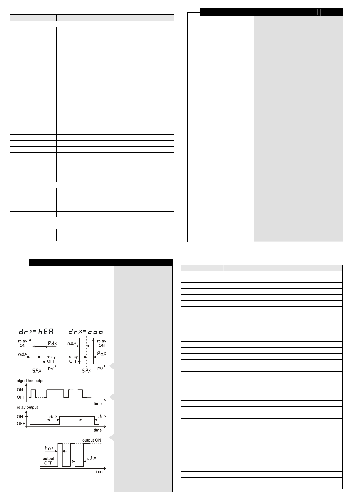
equipped ith up to 2 alarm outputs,
hich can control various actuators
using ON/OFF control algorithm,
and the optional RS485 interface
enables net orking.
The TC67U indicator allo s
adjusting of the built-in digital filters
and the programmable output delay,
resulting in increased operation reliability
in case of industrial interferences.
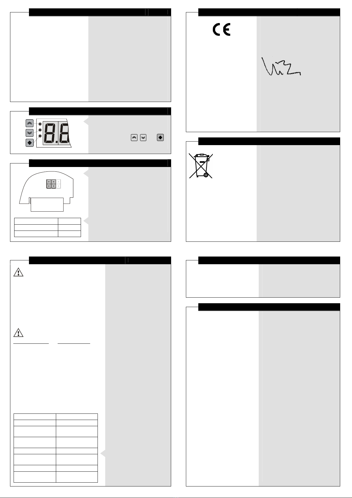
Controls
♦
Remove the front frame and panel
to reach the 3 hidden keys
next to the display.
♦
The key symbols , , and
are used further in this manual.
Input Setting
J1 J2
Input type short out
0...10 V J2
all the rest J1
♦
Open the case to reach
the configuration jumpers J1 and J2,
located on the main board.
♦
To set the desired input type,
short out the respective
configuration jumper.
Declaration of Conformity
15
The undersigned hereby declares,
on behalf of COMECO Inc.,
that this device has been manufactured
in compliance ith standards
EN 61000 and EN 61010,
and meets the requirements
of Directives 73/23/EEC and 89/336/EEC.
Vladimir Sakaliyski
CEO
COMECO Inc.
Waste Disposal
Do not dispose of
electronic devices
together with
household waste
material!
If disposed of ithin European Union,
this product should be treated
and recycled in accordance ith the la s
of your jurisdiction implementing
the WEEE Directive 2002/96
on the Waste Electrical and Electronic
Equipment.
Communication Protocol
14
Notes:
♦
TC67U adds 3 spaces
in the beginning of the response.
♦
TC67U returns decimal point
even when the value is integer.
♦
#13 (CR) is byte 0x0D;
#10 (LF) is byte 0x0A.
♦
The
U
255 command should be used
only in case just one slave is presented.
Protocol exa ples:
PC or other device: TC67U response:
activating device number 10
U10#13#10 ok.#13#10
reading filter time
f.t#13#10 f.t 0015.#13#10
riting filter time of 30
f.t 30#13#10 f.t 0030.#13#10
reading input value of 27.5
p.v#13#10 p.v 027.5#13#10
invalid command.
command not recognized
parity rror. parity error detected
not a numb r. attempt to write symbols
for numerical parameter
point rror. value resolution greater
than parameter’s one
out of rang . value out of range
unit is busy. writing is allowed only
to device at Basic level
r ad only. parameter is read-only
can't sav . problem with writing
in non-volatile memory
♦
The device remains active
until it receives another
U
х
command, but ith different
device address, a FAL
error, or ith reset.
♦
Any Baud Rate value change
through the communication
interface also deactivates
the device.
Reading fro a device
♦
If the frame consists of only
one ord, it is recognized
as a command for reading.
♦
The device responds to it by
returning the same ord and
its value, according to Table 2.
Writing in a device
♦
If the frame consists of
t o ords, it is recognized
as a command for riting.
♦
With riting, transferred
are the same t o ords
that ould have been
received at the respective
command for reading
from the device.
♦
After successful riting,
the device responds ith
the respective command
for reading, except for
the baud command.
Other device responses
♦
When Error Info value is -1,
the device substitutes any
command for rror reading.
♦
TC67U responses in case
of incorrect protocol use
are given on the left.
Reset
To reset the device,
send command r s t.
Mounting
3
♦
Place TC67U into a 136x66 mm
panel cut-out.
♦
Tighten it into place using
the enclosed mounting brackets.
Electro-Magnetic Interference (EMI) Issues
♦
All signal ires must be shielded.
They must not be packaged together
ith po er cables!
♦
Never lay the signal ires close
to inductive or capacitive noise
sources, such as relays, contactors,
motors, etc.!
♦
All shields have to be grounded ONLY
at one end, as closer as possible
to the indicator terminals!
♦
Avoid sharing supply lines
ith po erful consumers,
especially ith inductive loads,
s itched on and off.
♦
To stop un elcome interference
signals entering through the po er
supply lines, use shielded 1:1
isolation transformer!
♦
Shunt all s itched (not only those
s itched by the indicator) inductive
consumers ith special suppression
net orks: RC group and varistor -
for AC loads, or diode - for DC loads.
♦
If the indicator operates in a very
po erful EMI area, it has to be
mounted inside a grounded metal
shielding box!
♦
To protect the interface from electro-
magnetic disturbances, follo
the RS485 standard guidelines.