Comelit 41CPE118 User manual

Passion.Technology.Design.
EN
TECHNICAL
MANUAL
INSTALLATION AND PROGRAMMING MANUAL FOR
LOGIFIRE PANEL - 41CPE118

Table of contents
Warning
1. INTRODUCTION..................................................................................................................................................................................................4
1.1 GENERAL FEATURES ............................................................................................................................................................................................................... 4
1.1.1 Main technical features.................................................................................................................................................................................................. 5
1.1.2 Working environment ..................................................................................................................................................................................................... 5
1.1.3 Electrical specifications ................................................................................................................................................................................................. 6
2. INSTALLATION ....................................................................................................................................................................................................7
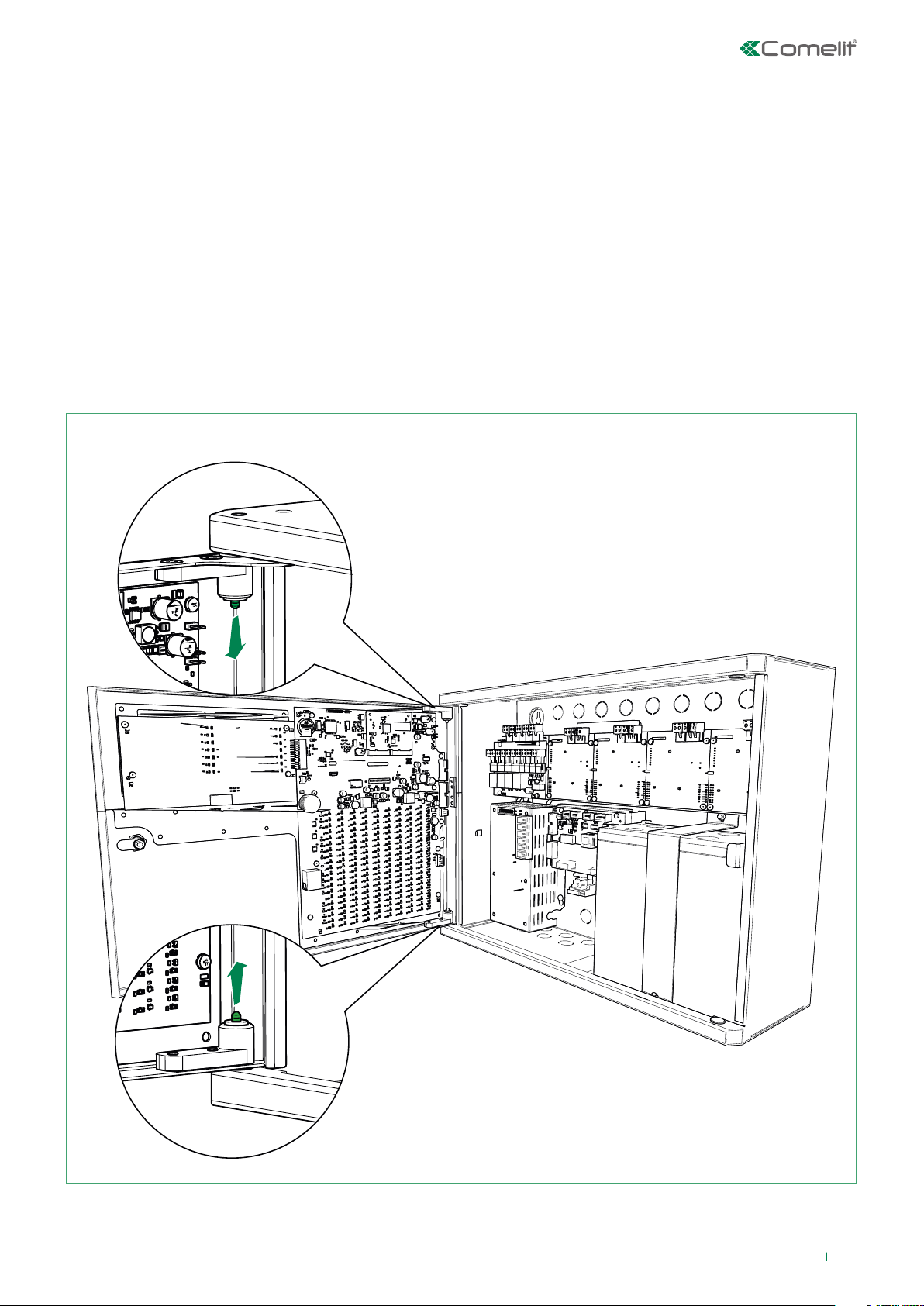
2.1 Removing the front door .......................................................................................................................................................................................................... 7
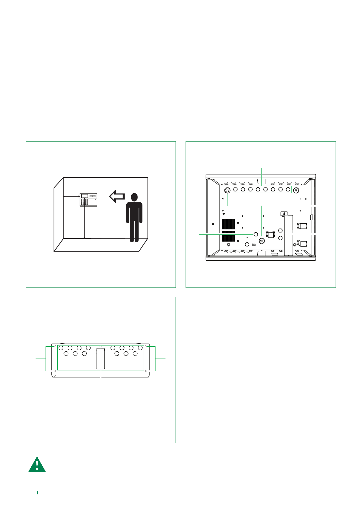
2.2 Wall mounting............................................................................................................................................................................................................................ 8
3. SYSTEM COMPONENTS....................................................................................................................................................................................9
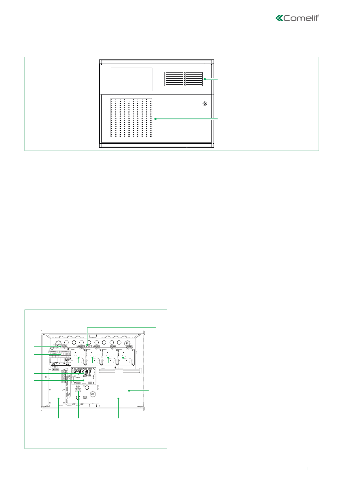
3.1 Front panel................................................................................................................................................................................................................................. 9
3.2 Internal modules for panel 41CPE118 (full configuration)..................................................................................................................................................... 9
3.3 Description of the motherboard elements............................................................................................................................................................................ 10
3.4 Monitored output module and relay module ........................................................................................................................................................................ 11
3.5 Connecting devices to the output module ........................................................................................................................................................................... 11
3.6 Loop Controller ....................................................................................................................................................................................................................... 12
3.6.1 4-Loop expansion box - 41CPE104 (optional) ............................................................................................................................................................ 14
3.7 Power supply unit - panel 41CPE118 .................................................................................................................................................................................... 15
3.7.1 Additional power supply unit – 41ALM172 (optional) ................................................................................................................................................ 16
3.8 Connecting the thermal printer - 41PRN100 (optional) ....................................................................................................................................................... 18
3.9 CONNECTING AND PROGRAMMING RS485 MODULE - 41ECB000 (optional)................................................................................................................. 19
3.10 CONNECTING THE LAN ....................................................................................................................................................................................................... 20
3.11 REPEATER PANEL 41CPR100 (optional)............................................................................................................................................................................. 21
4. PROGRAMMING ...............................................................................................................................................................................................22
4.0 BASIC PROGRAMMING VIA PANEL 41CPE118 TOUCHSCREEN....................................................................................................................................... 22
4.0.1 INITIAL STARTUP .......................................................................................................................................................................................................... 22
4.0.2 CHANGING THE LANGUAGE....................................................................................................................................................................................... 22
4.1 ACCESS CODES...................................................................................................................................................................................................................... 23
4.2 PROGRAMMING MENU.......................................................................................................................................................................................................... 25
4.3 DEVICES................................................................................................................................................................................................................................... 26
4.3.1 PERIPHIERY DEVICES.................................................................................................................................................................................................. 26
4.3.1.1 Current device state .................................................................................................................................................................................................. 27
4.3.1.2 Adding a new periphery device to the configuration ...................................................................................................................................... 27
4.3.2 LOOP DEVICES ............................................................................................................................................................................................................. 28
4.3.3. Addressing devices ..................................................................................................................................................................................................... 46
4.3.3.1 Setting an address.............................................................................................................................................................................................. 48
4.3.3.2 Changing an address ......................................................................................................................................................................................... 49
4.4 Zones........................................................................................................................................................................................................................................ 49
4.5 Logic inputs ............................................................................................................................................................................................................................. 51
4.5.1 Submenus for selecting the input type....................................................................................................................................................................... 53
4.5.2 INPUT GROUP - View and change .............................................................................................................................................................................. 59
4.6 Logic Outputs .......................................................................................................................................................................................................................... 59
4.6.1 Submenus for selecting the output type .................................................................................................................................................................... 61
4.6.2 Edit Outputs Map menu (entering input groups and checking the outputs)........................................................................................................... 64
4.7 PANEL....................................................................................................................................................................................................................................... 65
4.7.1 Changing the code and access level .......................................................................................................................................................................... 65
4.7.2 Network menu............................................................................................................................................................................................................... 66
4.7.2.1 Network Settings: ............................................................................................................................................................................................... 66
4.7.2.2 Panels .................................................................................................................................................................................................................. 67
4.7.3 Disablements menu...................................................................................................................................................................................................... 68
4.7.4 Sounders Mode............................................................................................................................................................................................................. 68
4.7.5 FIRE / EVAC panel interface module........................................................................................................................................................................... 70
4.7.6 Callpoints mode ............................................................................................................................................................................................................ 72
4.7.7 Selecting the language................................................................................................................................................................................................. 72
4.7.8 Delay (T1) ....................................................................................................................................................................................................................... 72
4.7.9 Printer ............................................................................................................................................................................................................................ 73
4.7.10 Company Logo............................................................................................................................................................................................................ 73
4.8 Restore Default ....................................................................................................................................................................................................................... 73
4.9 Save.......................................................................................................................................................................................................................................... 73
5. Maintenance .....................................................................................................................................................................................................74
5.1 Maintenance Menu.................................................................................................................................................................................................................. 74
5.2 Entering the time..................................................................................................................................................................................................................... 74
5.3 Entering the date..................................................................................................................................................................................................................... 74
2

5.4 Day Mode................................................................................................................................................................................................................................. 75
5.5 Setting Output Delays............................................................................................................................................................................................................. 75
5.6 View Event log ......................................................................................................................................................................................................................... 77
5.7 Tests ......................................................................................................................................................................................................................................... 78
5.7.1 Zone Test ....................................................................................................................................................................................................................... 78
5.7.2 Indication Test............................................................................................................................................................................................................... 79
5.7.3 Device Test .................................................................................................................................................................................................................... 79
5.7.4 Sounder Output Test..................................................................................................................................................................................................... 79
5.8 Disablements........................................................................................................................................................................................................................... 79
5.8.1 Disabling Loop Devices................................................................................................................................................................................................ 80
5.8.2 Zone Disablements....................................................................................................................................................................................................... 80
5.8.3 Zone Devices................................................................................................................................................................................................................. 81
5.8.4 Output Disablements.................................................................................................................................................................................................... 81
5.9 Software Revision ................................................................................................................................................................................................................... 81
5.10 Display.................................................................................................................................................................................................................................... 82
5.11 View enabled Isolators ......................................................................................................................................................................................................... 84
6. USER GUIDE .....................................................................................................................................................................................................85
6.1 System status bar ................................................................................................................................................................................................................... 85
6.2 Panel Status icons................................................................................................................................................................................................................... 85
6.2.1 Panel 41CPE118 mode icons ....................................................................................................................................................................................... 86
6.2.2 “Sounder Output” status icons.................................................................................................................................................................................... 86
6.2.3 “Fire Brigade Output” status icons ............................................................................................................................................................................. 86
6.2.4 “Fire Protection Output” status icons......................................................................................................................................................................... 87
6.3 Messages................................................................................................................................................................................................................................. 87
6.4 Access levels........................................................................................................................................................................................................................... 87
6.5 Main Display screen................................................................................................................................................................................................................ 87
7. Appendices .......................................................................................................................................................................................................88
4 Centrale di allarme antincendio 41CPE024 – Manuale di installazione e programmazione
Comelit Group S.p.A.
Via Don Arrigoni 5 - 24020 Rovetta S. Lorenzo BG Italy tel. +39 0346 750 011 - fax +39 0346 71436
DoP No: 045
EN 54-2:1997/A1:2006/AC:1999; EN 54-4:1997/A2:2006/AC:1999
41CPE118
Requisiti per la progettazione di centrali di controllo e segnalazione controllate via software
Caratteristiche essenziali
Prestazioni in caso di incendio Passato
Ritardo nella risposta (tempo di risposta all’incendio) Passato
Passato
Passato
Passato
Passato
Passato
ATTENZIONE!
Leggere attentamente le istruzioni prima di iniziare l’installazione del prodotto e conservarle per eventuali
necessità future. Le informazioni contenute in questo documento possono essere soggette a cambiamenti senza
preavviso.
ATTENZIONE!
Questo manuale contiene informazioni relative alle restrizioni e al funzionamento del prodotto, ed anche
informazioni sulle limitazioni nelle responsabilità del produttore. Il manuale va letto attentamente!
NORME E CONFORMITÀ
La centrale di allarme antincendio 41CPE118 è disegnata ai sensi, ed è conforme alle esigenze della norma EN
Prodotti da Costruzione).
21
1293
41CPE118
3

41CPE118 is an analogue fire alarm panel that can cover up to 500 zones; it is supplied by default with 1 Loop but this can be
expanded up to 4 using additional boards (Art. 41ECL120) connected directly in the panel itself. Its maximum expansion of 8
Loops in total can be achieved using the external 4-Loop box Art. 41CPE104 (1 Loop board by default).
The panel uses Comelit communication protocol which allows it to communicate with all new and old series of Comelit
analogue devices.
System installation must be planned carefully before the panel and devices are fitted, to avoid or considerably reduce problems
during this stage. This includes: assigning an address to every device and planning a name of up to 40 characters (including
spaces) for each address, thereby ensuring easy traceability of the device.
The devices must be grouped by Zone in compliance with current regulations for the construction of fire protection systems,
and with the safety plan for the building.
1. INTRODUCTION
Each 41ECL120 loop (Comelit communication protocol) offers the opportunity of connecting 250 devices
(modules and/or sensors, regardless of type).
FRONT VIEW OF PANEL 41CPE118
1.1 GENERAL FEATURES
The front panel has a colour touchscreen display (dimensions 155x86 mm) and LED indications for viewing events and zone
statuses.
Access to panel functions takes place via password for three individual access levels, while access to the internal components
of the panel is protected by a special mechanical key. The panel box is almost 150 mm deep, guaranteeing easy access and
laying of cables during installation, as well as quicker and easier wiring procedures.
Between one and four expansion boards 41ECL120 can be added to the output module.
The system can be expanded by connecting the panels in an Ethernet or RS485 network, where communication between them
takes place via TCP/IP PROTOCOL, up to a maximum of 64 control panels / repeater panels linked.
The panel has a built-in real-time clock and a calendar, allowing operation in day and night mode. Switching between the
two modes can take place automatically or manually. Events such as: FIRE, RESET, FAULT, etc., are saved in the memory, by
creating an Event Log file, which records the time, date, device address, device type (module or sensor), device name, zone,
zone name, etc. Events which can be easily viewed via the panel or printed directly on the thermal printer in real time (Art.
41PRN100) or by exporting the Log file via programming software.
4

1.1.1 Main technical features
• Loop controller - from 1 to 4 internal units (41ECL120), from 5 to 8 using box 41CPE104 (optional)
• Up to 250 devices (modules and/or sensors, regardless of type) for every Loop 41ECL120
• Max. current for each Loop board - 700 mA
• Display - 7” Resistive colour touchscreen (155x86 mm)
• Number of zones in the panel - 500
• Zone status repeater LED - 200
• Zone Groups - 48
• Communication protocol for Loop expansion devices 41ECL120 - Comelit
• ESPA 4.4.4 protocol - output from RS232 port (if selected)
• Monitored outputs - 4 (Sounders, Fire Brigade alarm transmission, Fault, Fire Protection):
◊ Sounders (SND) = 1A @ 24 VDC
◊ Fire Brigade alarm transmission (Fire R) = 100 mA @ 24 VDC
◊ Extinguishing (Fire P) = 100 mA @ 24 VDC
◊ Fault = 100 mA @ 24 VDC
• Monitored inputs - 4 (PrConf, FltPr, AlConf, Vds)
• Unsupervised relay outputs - 4 programmable - 30 VDC/10A (each)
• Logic inputs per panel - 250
• Logic outputs per panel - 250
• Programming in Day / Night mode
• Two alarm status levels - T1 and T2
• T3 for evacuation countdown
• Panel links - 64 max. between Comelit analogue panels or Repeater Panels 41CPR100
• Panel configuration via Ethernet or USB
• Connection with repeater panel 41CPR100 (optional)
• Connection with thermal printer 41PRN100 (optional)
• Connection with additional power supply unit 41ALM172 (optional)
• Flush mounting with frame 48BIA100 (optional)
• Designed for mounting in modular structures
• Multilingual menu
• Certification according to EN54-2, EN54-4, complies with EN54-13.
• 41CPE118 dimensions (LxHxD) - 430x330x150 mm
• Material – Metal
• Protection rating - IP 30
• Colour - Grey RAL 7045
• Weight - 7 kg
1.1.2 Working environment
• Operating temperature – from -10 to +50°C
• Relative humidity - up to 95% (without condensation)
• Storage temperature - from -10°C to +60°C
5

1.1.3 Electrical specifications
• Earthing
Earthing must be carried out in compliance with electrical safety regulations; the total resistance of the circuit must be lower
than 10Ω.
The earth wire must be connected to the “earth” input of the fire panel terminal.
• Main power supply
In normal conditions, the fire panel is powered by the mains electricity supply. If the mains power is cut o, the power supply
is guaranteed by means of a rechargeable backup battery. The electrical specifications of the main power supply are provided
below:
◊ Main power supply - 110-230 VAC
◊ Frequency - 50/60 Hz
◊ Backup power supply - for 4 Loops 1 x 12 V / 18 Ah SLA (Sealed lead-acid)battery; 2 batteries for 8 Loops
◊ Internal battery resistance - <0.3 Ohm
◊ Max. continuous output current Imax.a - 2.7A
◊ Max. output current (batteries not charged) Imax.b - 5.0A
◊ Min. output current lmin. - 0.2A
◊ Output voltage (U) - from 10.2 V to 14.3 V (13.65 V @ 20°C)
◊ Electrical output - 4 loops 14.8A / 8 loops 29.6A
◊ Operating temperature - from -5°C to +40°C
◊ Protection rating - IP 30
• Consumption
From the electricity mains in standby mode:
◊ Configuration with 1 loop: 65 mA AC
◊ Configuration with 2 loops: 75 mA AC
◊ Configuration with 3 loops: 85 mA AC
◊ Configuration with 4 loops: 95 mA AC
Only with backup power in “Fault” condition, generating the message “AC loss”:
◊ Configuration with 1 loop: 285 mA DC
◊ Configuration with 2 loops: 360 mA DC
◊ Configuration with 3 loops: 435 mA DC
◊ Configuration with 4 loops: 510 mA DC
• Power supply and battery
◊ Output voltage (U): 13.8 V
◊ Output current: 20A
◊ Internal rechargeable battery resistance Ri: <0.3 Ohm
◊ Battery: 1 x 12 V/18 Ah, SLA (Sealed lead-acid) type
◊ Battery dimensions: 167х181х76 mm
◊ Battery connection type: with ring terminal Ø5 mm (M5)
• List of fuses
◊ Main power supply: 4А, Type Т
◊ Outputs: 0.1А, Type PTC (3); 0.3A Type PTC (1); 1A, Type PTC (1)
◊ Battery: 15А, Type PТC
CAUTION: the fire alarm panel should not be installed near sources of strong electromagnetic fields (radio
transmitters, electric motors, etc.)!
CAUTION: the panel should only be installed by qualified personnel.
The electronic components in the panel are vulnerable to electrostatic discharge.
NEVER make hardware changes when configuring the panel while the main or backup power supply is
enabled!
6

2. INSTALLATION
The fire panel should be installed in a clean, dry place where it will not be subjected to knocks or vibrations. The panel is not
waterproof!
It must be positioned away from sources of heat, and the ambient temperature must be between -5ºС and + 50ºC.
2.1 Removing the front door
To make installing the panel easier, the front door can be removed using the spring-loaded pins inside the panel.
To remove the door, disconnect the flat connection cables originating from the boards inside the panel; use a slotted
screwdriver to lift the pin at the bottom and shift the door outwards so that the pin comes out of its guide hole, then repeat the
same procedure for the pin at the top and unhook the door.
To re-fit the front door, insert the top pin into its hole; use a slotted screwdriver to lift the bottom pin (or do so manually) and
position the door inside the panel frame, so that the second pin also slots into its hole. You will hear it click into place when the
correct position is found. Make sure the door is secure and reconnect the flat cables.
7

2.2 Wall mounting
• Proceed with wall mounting using the paper template and secure the bottom of the panel using the wall anchors and
screws provided.
• Choose the inputs for the signal cables (loops, sounders, etc.) and for the main power supply cable, and remove the pre-
perforated metal plugs only from the holes used to route the cables.
• Route the cables over the metal base of the panel.
• Connect the mains power supply and the earth cable to the power supply terminal and make sure the connections are
secure; DO NOT switch on the main power supply at this stage.
• Position the battery upright and secure it with the metal clamp.
• Perform the necessary cable wiring.
• Once the connections have been made, power the panel; after the test phase is complete and when the panel is working
normally, close the front door using the key supplied.
• Keep the keys in a safe place that can only be accessed by authorised technical personnel.
400mm
1500mm
1
2
34
5
6
6
1. Holes for fixing the panel to the wall
2. Cable routing holes
3. Electrical power cable routing hole
4. Battery support bracket
5. Cable routing opening
6. Holes provided for modular mounting
CAUTION: fire panel 41CPE118 is also designed for flush mounting in conjunction with frame Art. 48BIA100.
8

3. SYSTEM COMPONENTS
3.1 Front panel
Description of LED indications:
• FIRE ALARM: lit steadily in the event of a common fire alarm
• PREALARM: indicates one or more Zones in PreAlarm status
• FAULT: general fault indication (e.g. Device, Device or Panel output, etc.)
• SYSTEM FAULT: indication in the event of a system fault (e.g. Processor)
• SILENCE: general indication for silenced alarms
• DELAY: general indication of a delay for one or more outputs in the system
• AC VOLTAGE: indication that 230 V mains voltage is present
• DISABLEMENTS: indication of active system disablements (e.g. buzzer, device disabled, etc.)
• TEST: lit steadily in Test mode
• WARNING: indication that a technical warning has been received (e.g. input/output of a device enabled)
• ALARM CONFIRMED: indication received from alarm signalling equipment
• OUTPUTS FAULTY/DISABLED: monitored alarm output faulty / disabled
• CONFIRM POWER DOWN: confirmation of the indication received from fire protection equipment
• POWER DOWN FAULT: fault indication received from fire protection equipment
3.2 Internal modules for panel 41CPE118 (full configuration)
1
234
5
6
7
8
9
10
1. Rechargeable 12 V / 18 Ah battery
2. Battery support bracket
3. Terminal block for connection of the main 230 V power
supply (4A fuse)
4. Main power supply unit
5. 41ECB000 redundant RS485 BUS expansion module
(optional)
6. Module for interfacing with voice evacuation panel (RJ45)
and RS232 port (printer connection or ESPA 4.4.4 protocol
interfacing)
7. Module with 4 relay outputs and voltage-free switching
contacts, plus 4 monitored inputs
8. Module with 4 monitored outputs
9. Loop boards from 1 to 4 (1 by default)
10. Facility for securing earth terminal block
Indicator LED
Zone indication LED
9

3.3 Description of the motherboard elements
The motherboard is located on the inside of the front door of panel 41CPE118; the uPC control module, which monitors the
panel functions and procedures, is mounted on it.
CAUTION: adjustments and changes to the motherboard must ONLY be implemented by authorised
personnel!
1
2
3
4
5
6
7
8
9
10
Motherboard elements:
1. LAN - RJ45 port for network connection
2. USB - Micro USB connector for programming via panel firmware updating software
3. uPC - Control module
4. Restore Defaults* – Jumper for restoring the panel to its factory values
5. Ajax – AJAX LAN connector
6. Connector for box 41CPE104
7. JPOUT1 - Flat cable for interface module connection
8. JPIN1 - Flat cable for output module / loop expansion connection
9. Buzzer
10. Backup battery
*CAUTION: if JPRESET is closed, every time the panel comes on, it will be set to its factory values; all
programming saved on the panel will be lost!
10

3.4 Monitored output module and relay module
The output module is a fundamental element of the fire panel, which allows equipment and devices to be connected directly
via the panel. It has 4 programmable switching relays with voltage-free contacts, 4 monitored outputs, an AUX output for
external power supplies and 4 monitored inputs.
Output module
4 Relay Module
REL 1 REL 2 REL 3 REL 4
24V
GND
SND
FAULT R
FIRE R
FIRE P
+ - - + - + - + - +
EFlt
Loop
Description of the monitored output module terminal block:
• +24 V – Auxiliary output, 24 VDC @ 0.3A
• GND – Auxiliary output common earth
• SND – Monitored output for connection of sounders or visual/audible signalling devices. Enabled if there is an ACTIVE loop
sounders event. 24 VDC / 1A
• FIRE R – Monitored output for the connection of external devices such as equipment for fire alarm transmission to the Fire
Brigade. Comes on in the event of a Common Fire Alarm. 24 VDC / 100 mA
• FIRE P – Monitored output for the connection of external devices such as fire protection and extinguishing equipment.
Comes on in the event of a Common Fire Alarm. 24 VDC / 100 mA
• FAULT R – Monitored output for the connection of external fault indication devices. This output is DISABLED in the event of
a common fault. 24 VDC / 100 mA
Description of the terminal block for the 4 relay output module:
• REL 1, REL 2, REL 3, REL 4 – Relay outputs with switching (N.C. – COM - N.O.) voltage-free contacts, freely programmable
via the fire panel settings. 30 VDC/10A (each)
• PrConf, FltPr, AlConf, Vds - Monitored inputs for indicating the fire protection and extinguishing equipment status.
CAUTION: It is essential to connect a 10 kOhm terminal resistor in parallel to the furthest device from the
panel in the monitored circuit, so that the panel can constantly check whether the circuit is intact. See
examples below.
The FIRE R outputs (Fire Brigade alarm transmission) and FIRE P (extinguishing) are monitored outputs; the first is dedicated
to the connection of equipment providing fire alarm indications to monitoring authorities, while the second is used to send
activation commands to fire protection and extinguishing systems.
N.B.: The FIRE R and FIRE P outputs are enabled in the event of a “Common Fire Alarm”.
Connection example for an indication device, connected to the FIRE output.
3.5 Connecting devices to the output module
Others:
• Loop - Interface connector for loop expansion connection
• EFlt - Jumper for enabling/disabling Earth Fault indication (Jumper closed, Earth Fault indication enabled)
11

The SND monitored output (sounders) is dedicated to the connection of conventional sounders. The maximum number of
sounders connected to the output must not exceed a current of 1A.
Note: The SND output is enabled if there is a “Loop sirens active” event.
Note: If the sounders are set to “Flash only” it is not considered a Loop sirens active event. The SND output is not
enabled.
N.B.: Press the “Silence Sounder” button to disable the SND output.
Connection example for an indication device, connected to the SND output.
3.6 Loop Controller
Panel 41CPE118 communicates with Loop Controllers (41ECL120) using Comelit communication protocol.
Connection of Loop boards takes place via a “comb” terminal, where the first board (supplied by default inside the panel) is
connected to the output module.
The Loop expansion has 2 main functions:
1. It collects data from the devices connected to the communication line and transmits this data to the output module.
2. It receives commands from the output module and transmits them to the devices connected to the communication line.
Up to 250 devices can be connected to each Loop controller 41ECL120.
The maximum absorption of the devices on each Loop board should not exceed Imax = 700 mA.
If consumption exceeds this value, an overload protection will be triggered.
12
1. “Comb” terminal for connecting the Loop board to the output module or to a second Loop board
2. “Female” connector for connecting a Loop board inside panel 41CPE118
12

Adding a Loop board inside panel 41CPE118
CAUTION: ALWAYS cut off the mains (230 V) and backup (battery) power for the panel when adding or
removing a Loop expansion.
Modulo I/O
1. Insert the connectors on the second Loop expansion into the terminal on the first.
2. Secure the second Loop board to the metal frame using the screws provided.
N.B.: The third and fourth expansion boards are added in the same way, as illustrated in the figure.
First Loop expansion Second Loop expansion
13

41CPE104 technical / electrical specifications
• Loop controller – from 1 to 4 (1 by default)
• Up to 250 devices (modules and/or sensors, regardless of type) for every Loop 41ECL120
• Max. current for each Loop board - 700 mA
• Communication protocol for Loop expansion devices 41ECL120 - Comelit
• Monitored outputs - 1 (SND) for sounder connection = 1A @ 24 VDC
• Certification according to EN54-2, EN54-4 and complies with EN54-13
• Main power supply - 110-230 VAC
• Frequency - 50/60 Hz
• Battery – 1 x 12 V / 18 Ah, SLA (Sealed lead-acid) type
• Battery connection type: with ring terminal Ø5 mm (M5)
• EFlt - Jumper for enabling/disabling Earth Fault indication (Jumper closed, Earth Fault indication enabled)
• Dimensions (LxHxD) - 430x330x150 mm
• Material – Metal
• Protection rating - IP 30
• Colour - Grey RAL 7045
• Weight – 7 kg
• Operating temperature – from -10 to +50°C
• Relative humidity - up to 95% (without condensation)
• Storage temperature - from -10°C to +60°C
• Designed for mounting in modular structures
3.6.1 4-Loop expansion box - 41CPE104 (optional)
Expansion box 41CPE104 for panel 41CPE118 is supplied as standard with 1 Loop, which can be expanded to 4 using 3
boards 41ECL120. This means fire panel 41CPE118 can reach its maximum expansion with a total of 8 Loops. Up to 250
addressed devices (detectors, buttons, I/O modules, sounders, etc.) can be connected to each loop. It has a tough grey metal
container which is the same size as the panel and other Comelit modular boxes, to guarantee its modularity and ensure it can
be fitted alongside other boxes during installation.
It has a 14A power supply unit with a 12 V battery output (12 V / 18 Ah).
Certification according to EN54-2, EN54-4 and complies with EN54-13.
Fitting and connecting the communication cable
Combining and fitting modular structures takes place using the screw kit provided.
To connect the communication cable between box 41CPE104 and fire panel 41CPE118, simply connect the flat cable located
inside the additional box to the dedicated terminal inside panel 41CPE118.
14

3.7 Power supply unit - panel 41CPE118
FUNCTION DESCRIPTION
-Board power supply
+
+13.8 V Additional power supply unit input
IN Input for connection of the additional power supply unit output (Fault Out)
OUT Error output, enabled when problems arise with the power supply voltage.
It is connected to the additional power supply unit input (Fault In)
GND Input for connecting the additional power supply unit to earth
Description of the power supply unit terminal block
Before connecting the main power supply, make sure each Loop, sounder or other input / output is connected correctly and
the earth cable is connected.
230 V power supply LED
Panel communication LED
4A fuse
Rechargeable sealed
lead battery 12 V / 18 Ah
Main power
supply
Red
Black
Connect the red cable to the positive battery pole, and the black cable to the negative pole.
The two cables should be connected to the battery by means of a Ø5 mm ring terminal.
Position the temperature sensor behind or underneath the battery to ensure the temperature value is read correctly.
CAUTION: When connecting the battery to the power supply unit, several details must be taken into
account.
• Only use batteries which are the correct size with the electrical specifications as indicated by the
manufacturer.
• Before connection to the power supply unit, check the battery polarity.
• The battery cannot power the panel before the mains power is switched on.
• Battery recharging takes place at a maximum current of I = 2A and voltage U ≤ 13.8 V.
15

3.7.1 Additional power supply unit – 41ALM172 (optional)
Unit 41ALM172 is a power supply unit designed to supply additional power to addressed fire panel 41CPE118. The power
supply unit is housed in a metal container suitable for creating a modular structure with the addressed panel and a second
power supply unit. Access to the main board and the cable connections is guaranteed by a special key (supplied). The status
of unit 41ALM172 is shown via specific LED indications on the PCB. The status of the power supply unit can be monitored
constantly by enabling the option “Check external power” in the menu of panel 41CPE118. To access the menu for this
function, proceed as follows:
SYSTEM – PROGRAMMING – DEVICES – PERIHPERY and enable CHECK EXTERNAL POWER on the fire panel.
When the option is enabled, the panel will display an error message “External Power Supply Fault, Periphery Device 1-PSU” in
the event of problems with the power supply unit. The corresponding power supply fault will be indicated by an LED flashing
on the PCB.
During normal operation, only the green “OK” LED flashes and all the other LEDs are o. If the main power supply (230 V~) is
cut o, the yellow “FLT” fault LED starts flashing and the green “OK” LED turns o. If there are problems with battery 1 and/or
2, the yellow LEDs for sections Batt1 and/or Batt2 will flash.
For a detailed description of all the LED indicators, please refer to the technical manual for 41ALM172.
Connection
The connection diagram for a panel 41CPE118 with 2 additional power supply units 41ALM172 is shown below:
41ALM172
Main board
(first)
41ALM172
Main board
(second)
RED
BLACK
NOTE: On the FLT terminals, the arrows facing in the inside of the main board for the 41ALM172 indicate the terminals for
board input signals, while the arrows facing outwards indicate the terminals for board output signals.
CAUTION:
• Switch off the main power supply and the battery for panel 41CPE118 before installing the power supply
unit 41ALM172!
• Only use the connection cables supplied with the equipment: red and black cables for connection to the
JP4 terminals; white and grey cables for connection to the FLT terminals! Do not shorten or lengthen
these cables!
• Perform all wiring in observance of the connection polarities, following the connection diagrams shown.
If, after switching on power supply unit 41ALM172, the “INCORRECT CONNECTION” LED is on, switch
off the power supply immediately and check the connection between the power supply unit for panel
41CPE118 and the JP4 terminals on 41ALM172!
• If the “High resistance” LED for Battery 1 or 2 is flashing, we strongly recommend you replace the
batteries immediately!
16

41ALM172 technical / electrical specifications
• Main power supply - 230 V~ +10%/ -15%, 0.6A, 4A fuse
• Frequency - 50/60 Hz
• VDC output:
◊ Voltage - 9.9-14.2 Vdc
◊ Maximum current - 7A@1 battery, 14A@2 batteries
• Internal battery resistance Ri - < 0.3 Ohm
• Maximum battery capacity - 2x12 V/18 Ah
• Charger output - 13.65 Vdc ±1%@20°C, max. 2A
• Dimensions (LxHxD) - 430x330x150 mm
• Material – Metal
• Protection rating - IP 30
• Colour - Grey RAL 7045
• Weight – 6 kg (without batteries)
• Operating temperature – from -5 to +40°C
• Relative humidity - up to 95% (without condensation)
• Storage temperature – from -10 to +60°C
• Flush mounting with frame 48BIA100 (optional)
• Designed for mounting in modular structures
• Certification standards – EN54-4, complies with EN54-13
17

3.8 Connecting the thermal printer - 41PRN100 (optional)
Thermal printer for addressed panel 41CPE118, with a tough grey metal container which is the same size as the panel and
other Comelit modular boxes, to guarantee its modularity and ensure it can be fitted alongside other boxes during installation.
Allows the operator to print events such as: alarms, faults, activations and technical warnings, recorded in the panel memory.
The memory has a capacity of 10240 events, which are saved and printed with the date and the time at which the event
occurred.
2 LEDs on the front door show the status of the printer. Connection to the 41CPE118 panel takes place via RS232 serial
interface; the connection cable is supplied with the printer and should be connected TO THE RS232 PORT of panel 41CPE118.
To ensure the 41PRN100 printer communicates with panel 41CPE118, access the fire panel menu, logging in as a level 3 user,
and carry out the following steps in sequence:
SYSTEM – PROGRAMMING – PANEL – PRINTER
In the Printers menu, select “Printer 41PRN100” and save the changes.
Make sure the printer is working properly.
Panel 41CPE118 supports operation with external Canon 9 type printers, Kafka and Datecs models.
To connect the panel to the printer, you need to prepare a special cable – connect two male connectors DB9-DB9 (Datecs) and
DB9-DIN5 (Kafka).
Before starting to print, check the connections between the printer and the fire panel.
To panel
To printer, Datecs
type To panel
To printer, Kafka
type
Connection diagrams for an external thermal printer.
41PRN100 technical / electrical specifications
• Main power supply - 110-230 VAC
• Frequency - 50/60 Hz
• Dimensions (LxHxD) - 430x330x150 mm
• Material – Metal
• Protection rating - IP 30
• Colour - Grey RAL 7045
• Weight – 5.5 kg
• Operating temperature – from -10 to +50°C
• Relative humidity - up to 95% (without condensation)
• Storage temperature - from -10°C to +60°C
• Flush mounting with frame 48BIA100 (optional)
• Designed for mounting in modular structures
18

3.9 CONNECTING AND PROGRAMMING RS485 MODULE - 41ECB000 (optional)
The addressed fire alarm panel 41CPE118 is designed for connection in a redundant serial communication network of several
41CPE118 panels, 2-Loop panels Art. 41CPE112 and repeater panels 41CPR100, up to a maximum of 64 panels in the
network, guaranteeing a backup connection line in case of an individual fault with the physical support. The redundant network
is based on the RS485 communication interface, where the maximum distance between two 41ECB000 boards (or repeater
panel) should not exceed 1000 m.
CAUTION: The network module should only be added to the panel configuration and connected to the voice
interface board WHEN THE MAIN AND BACKUP POWER SUPPLY IS SHUT OFF!
To program the 41ECB000 module, access the 41CPE118 panel menu, logging in as a level 3 user, and carry out the following
steps:
SYSTEM – PROGRAMMING – PANEL – NETWORK – NETWORK SETTINGS
In the Network Settings menu, set:
NETWORK STATUS = ENABLED
NETWORK TYPE = RS485
PANEL NUMBER = X(set a dierent number for every piece of equipment in the network)
Save the changes.
To enable board redundancy, still via the NETWORK SETTINGS menu, press MORE and set REDUNDANCY = ON, then save
the changes.
N.B.: remember to assign a different number to each panel/repeater panel, so that you do not create duplicate panel
addresses.
To store and add all panels linked to the RS485 network to the programming, carry out the following steps:
SYSTEM – PROGRAMMING – PANEL – NETWORK – PANELS
In this menu, use the arrows to scroll through the panels in the system; you will only be able to see the IP code and status
(present, fault...) of the panel on which you are working. On the other panels in the network the ADD button will be active;
when you press it the second panel will be added to the network configuration.
At this point, select what the second panel should send or receive from the other connected panels:
RECEIVE MESSAGES: when this is enabled, the panel will receive all incoming messages from other linked panels (technical,
fault, alarm messages...)
RECEIVE COMMANDS: when this is enabled, the panel will receive all incoming commands from other linked panels
(evacuate, activate sounders, silence buzzer/alarm command)
SEND COMMAND: when this is enabled, the panel will be able to send commands to other linked panels (if these are enabled
to receive commands from other connected panels)
In the same PANELS menu section, press MORE to enable or disable some repeater functions:
REPEAT SOUNDER: when this is enabled, sounder and SND output activation on the panel is repeated for the other panels
REPEAT FIRE BRIGADE: when this is enabled, monitored Fire Brigade output activation is repeated for the other panels (FIRE
R alarm transmission)
REPEAT FAULT OUTPUT: when this is enabled, Fault indications are repeated for the other panels
REPEAT FIRE PROTECTION: when this is enabled, activation of the monitored output dedicated to extinguishing is repeated
for the other panels (FIRE P)
Connect the module in the panel to the dedicated terminal.
19

41ECB000
FIRE / EVAC INTERFACE
MODULE
41CPE118
FIRE PANEL
41CPE112
FIRE PANEL
41CPR100
REPEATER PANEL
REDUNDANT BUS
MODULE 2
REDUNDANT BUS
MODULE 1
41CPE118 41CPE118 41CPE112
41CPR100
UP TO 64 PANELS IN A REDUNDANT NETWORK
41ECB00041ECB00041ECB000
24 VDC
External
power supply
3.10 CONNECTING THE LAN
Up to 64 fire panels 41CPE118 can be connected in a LAN connected to a switch; using TCP / IP protocol and via a supervisor
PC, the status of the individual fire detection panels can be monitored and commands executed for them.
To use the LAN module, the installer must set the panel Network Type as “LAN”, see Network Settings menu.
The Ethernet port used for LAN cable connection is located on the motherboard inside the front door of the panel.
20
Table of contents
Other Comelit Fire Alarm manuals
Popular Fire Alarm manuals by other brands

Eaton
Eaton SQUASHNI MICRO Technical data

Simplex
Simplex LifeAlarm 4005 Series Programming instructions

Potter
Potter PAD100-PSSA installation manual

Panasonic
Panasonic Firetracker FT1020G3 CIE Technical and Programming Manual

Honeywell
Honeywell SILENT KNIGHT SK-5208 Installation and operation manual

Bosch
Bosch FSM-2000 installation guide

Elkron
Elkron HPA700MF manual

Kidde
Kidde VS Series Technical reference manual

Bosch
Bosch FAP-420 Series quick guide

Fire-Lite Alarms
Fire-Lite Alarms Fire-Watch 411UDAC Installation, programming, troubleshooting and operating instruction manual

Zeta Alarm Systems
Zeta Alarm Systems 80-210 installation guide

Honeywell
Honeywell Notifier LCD2-80 instruction manual