5
1 DESCRIPTION AND OPERATION
1.1 Introduction
This document was written to provide information regarding the technical specifications, connections,
installation, configuration and operation of the IFT-P unit.
The IFT-P aspirating detector intervenes promptly by analysing the air extracted by means of a pipe
network.
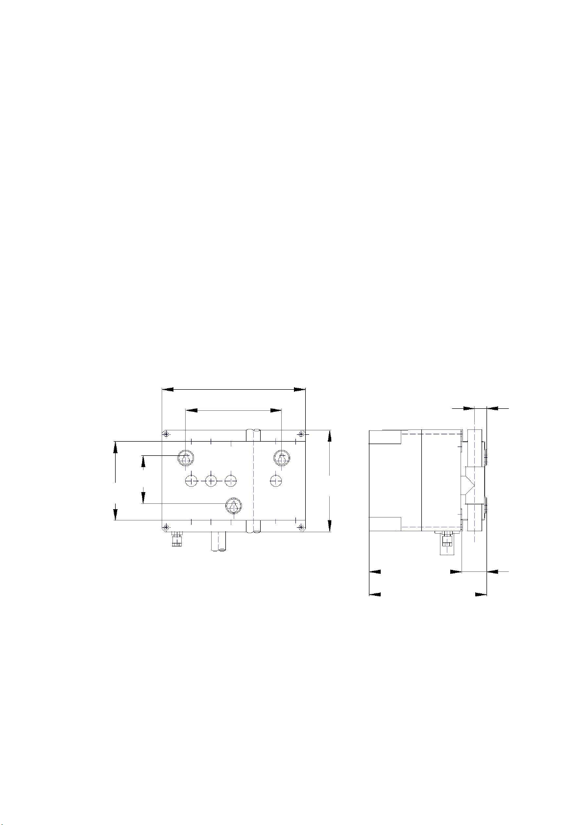
Figure 1-1: IFT-P
1.2 Operating principle
The air is extracted from the protected area by means of the pipe network. These pipes should usually be
drilled in accordance with project specifications. The air is then drawn in through the inlet collectors, where
the air sample is then combined, filtered and finally channelled towards the laser analysis chamber. IFT-P
can be used in conjunction with a Tee fitting collector to connect two inlets.
IFT-P monitors the airflow for both inlets. The analysis chamber consists of an optical chamber crossed by
a laser beam, through which the air sample passes. Inside, a photoelectric sensor measures the amount
of laser-produced light reflected by the particles of smoke as they pass through. Although clean air
generates a minimal amount of refraction, smoke increases this phenomenon and can therefore be
identified. If the configured smoke levels are exceeded, various alarm indications of increasing severity are
reported (Alert, Action, Fire1 and Fire2). These indications will be linked to one or more alarm relays
configured to switch at specific smoke levels, which will be connected to the fire alarm panel.