manuals.online logo
Brands
  1. Home
  2. •
  3. Brands
  4. •
  5. COMEPI
  6. •
  7. Switch
  8. •
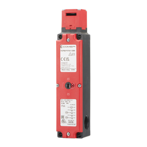
  9. COMEPI COND.01 User manual

COMEPI COND.01 User manual

Operating instructions –Electromagnetic safety limit switch 010 ISTR 06 SC 0418-00
The product EC declaration is available in the Download section of the site www.comepi.it or contacting the address [email protected]
DDC 16 –Electromagnetic switches and separate actuator with RFID coding series FEP-RFID
COMEPI safety switches are conceived and manufactured according to the
international IEC standards and to the European EN standards. These devices
are suitable for machines where hazardous conditions continue after the stop
signal and they can be used to manufacture safety systems in compliance with
standard ISO14119. Since their purpose is to protect operators, any unsuitable
installation or tampering with the devices can injure people seriously.
Therefore, the installation must be carried out according to the standards in
force and by authorized personnel only. We also recommend checking the
switch before starting the machine and checking periodically the correct device
operation.
The aim of this document is to give information for a correct installation of the
device, including a suitable connection and a safe application according to the
standards in force.
Choice of the most suitable operating principle
The device can be bought in two different versions, with a different locked
actuator. The M version is based on the actuator lock with deenergized
solenoid. The E version includes the actuator lock with energized solenoid. In
the M version the lock is preserved and it is impossible to reach dangerous parts
even in case of a voltage drop. On the contrary, the E version allows reaching
immediately the dangerous area even if the power is switched off suddenly. A
serious risk assessment must be carried out to choose the right device. If the
two models are used without lock function, they can be used interchangeably.
Device start up
The FEP-RFID device is supplied with a coded actuator with RFID technology.
The actuator supplied has been coupled to the device by the manufacturer, so
it is ready to be used. The actuator to use is univocal, it is possible to couple
other devices, but each new actuator coupled replaces the previous one. The
actuating head cannot be disassembled by the user, so we recommend
choosing the right one before buying the product. The actuator supplied is a
high coding level actuator according to standard EN ISO 14119, so the measures
against any easy bypass strategy for low coding level devices are not necessary.
In any case make sure the device is installed in places that cannot be reached
easily by unauthorized personnel.
Coupling of a new actuator
If the actuator is broken, it can be replaced with original COMEPI spare parts.
To couple the new actuator remove the FEP device cover and insert the
actuator into the slot so that the TAG area is coupled to the lower part of the
head. Use a pin to reach the coupling button with a hole on the internal cover.
Hold down till the three signalling LEDS flash green simultaneously. The new
actuator is coupled and ready to be used. The old actuator has been replaced
and its TAG is no longer recognized by the device unless it is coupled again.
Warning: the actuator TAG and the device antenna cannot be removed from
their seat, since they are sealed so that they cannot be bypassed easily.
Device wiring
The device can be supplied with an M12 connector, already connected by the
manufacturer, or with a threaded hole for cable gland M20x1.5. In the second
case the device must be wired using the terminals supplied to the user. Do not
drill the device to wire it, but use only the available hole. Wire the device
according to the operating diagrams shown below and using conductors with a
size between 0.34mm2and 1.5mm2. It is advisable to tighten the terminals with
a torque equal to 0.5 Nm, with a maximum of 0.8 Nm. Any incorrect wiring as
well as any wiring carried out using unsuitable conductors can seriously
compromise the operation of the device itself, jeopardizing the right safety
functions. To reach the terminal area remove the main cover, fixed with four
screws. Never remove the secondary internal cover: if this prescription is not
complied with, the correct operation of the device can be compromised and its
safety functions can be prevented. Close again the cover with a tightening
torque between 0.5 Nm and 0.8 Nm. Any incorrect cover closing can
compromise the IP degree of protection indicated by the manufacturer. Use
only cable glands guaranteed to ensure the IP degree of protection required by
the application.
Fastening of the device
The device must be fastened securely to the structure, using 4 M5 screws
whose length is not lower than 45mm. Strictly avoid fastening the device using
less than four screws. Any incorrect fastening can compromise the right safety
functions. The screws used must bear a tractive force of at least 1200N,
otherwise the lock is not guaranteed. Tighten the screws with a torque between
2 and 3 Nm. We recommend using screws that cannot be easily tampered with,
so that their fastening cannot be bypassed by unauthorized personnel. We also
recommend fastening the device in the high part of the structure, to prevent
dirt and dust from compromising its operation. The actuator must be fastened
to the protection in such a way that it cannot be removed, as prescribed by
standard EN ISO 14119. The actuator must be fixed with four M5 screws with a
length of at least 20mm. The device cannot be fixed using a lower number of
screws. The screws must bear a tractive force of at least 1200N, otherwise the
device lock function is not guaranteed. Tighten the actuator screws with a
torque between 2 and 3 Nm. The device and the actuator must be correctly
aligned after being fixed. Although the actuator is adjustable, too much
misalignment can cause mechanical problems and break the device itself.
Adjust the actuator manually, without using any tool that could break or
damage it. Check periodically the correct alignment of the actuator with the
device. If the actuator breaks, replace it. In case the device is damaged, replace
it completely. Do not use the limit switch as mechanical lock.
Auxiliary release with safety screw
The device has an auxiliary release with safety
screw. The arrow on the cover indicates the device
status. The release is enabled by loosening the
safety screw and by turning 180°. The device is
supplied with the safety screw sealed with paint in
order to prevent any misuse of the release function.
Connections
The safe outputs of the device must be connected to a safety module or to a
safety PLC to be correctly controlled and to ensure the right operation of the
safety system. This device ensures the safety of people and of the equipment,
so it is strictly forbidden to bypass its functions by avoiding its correct
installation. Remember that the system safety category does not depend
exclusively on the device, but also on the connections and on the other
external devices involved in safety. Before connecting the device make sure it is
intact in all its parts, as well as the cables used for connecting. Avoid bending
too much the conductors to reduce the risk of power failures or short circuits.
Before starting the device check the machine is in compliance with the
standards in force and with the requirements of the EMC Directive. Do not start
it in safety systems that do not comply with the requirements of the standards
in force. In case of problems to understand this document or the device
operation, always contact COMEPI technical support.
Maintenance
Do not disassemble and do not try to repair the device. In case of damage or
failure replace the whole device. The sequence of the functional tests the
device will be subject to are under the installer’s responsibility. We recommend
checking, according to the timing arrangements, the following functions: ①
Lock the protection and start the machine; it must be impossible to open the
protection ②Stop the machine and open the protection; the machine must
not start ③When the protection is closed, without enabling the device lock,
the machine must not start ④Check visually the device status ⑤Check
visually the actuator status ⑥ Check that the device has not exceeded its
service life according to the supposed operating frequency or to a meter. In any
case the device must be replaced after 20 years of service.
Other installation precautions
Before starting the device check the correct operation of the safety system -
Periodically check the correct operation of the device as specified in the
maintenance section - The installation must be carried out only by authorized
and qualified personnel - The use of the device must be limited to the
applications in compliance with the regulatory requirements - The device
installation and the safety system design must be carried out only by people
who know the regulatory references - The device installation and the safety
system design must be carried out in compliance with the standards in force -
In case of doubts or of special applications contact COMEPI technical support –
Enclose this document to the technical file and to the operating instructions of
the machine where the device is installed - Make always available this
document for the personnel who works on the machine where the device is
installed - During installation and operation, prevent dust and dirt from
entering the slot when the drive key is not inserted - Before any painting work
cover the slots and the identification label - Do not remove the identification
label, otherwise the compliance with the EC Declaration connected to the
device itself may be compromised - Do not install if there are strong vibrations;
All shocks and vibrations can prevent the correct operation of the switch - Do
not modify the device as it is - Do not disassemble and reassemble the
actuating head: if this operation is carried out incorrectly, it could cause
malfunction - Do not remove the secondary internal cover - Do not disassemble
and reassemble the microswitch: any approximate positioning could prevent
the correct operation. Use only suitable actuators supplied by COMEPI and
concerning the model used, otherwise safety is not guaranteed - Install the
actuator so that it does not injure the operator when the door is open - Replace
the device after exceeding the mechanical durability limit - During wiring keep
the load below the value of the category of use - Connect the safety contacts
to a protection fuse - Before reaching the switch contacts make sure to
disconnect the power supply from the device - Tighten the screws with the
torques indicated in this document - The end-of-life device must be correctly
disposed of, according to the laws of the country where it is disposed of.
Operating instructions –Electromagnetic safety limit switch 010 ISTR 06 SC 0418-00
The product EC declaration is available in the Download section of the site www.comepi.it or contacting the address tecnico@comepi.it
DDC 16 –Electromagnetic switches and separate actuator with RFID coding series FEP-RFID
Limits of use
Use the switch in compliance with the standards in force, according to the
instructions and using it according to its limits of operation. In case of improper
use, non-compliance with the instructions, assembly and maintenance carried
out by unauthorized or unskilled staff and failure to perform the functional
tests, the manufacturer is not liable at all. Do not use the device separately to
ensure safety in those areas where the operator can enter with all his body
within the perimeter. Any unintentional closing of the protection behind the
operator could cause dangerous situations for the operator himself. Do not use
in places with continuous changes in temperature, that could cause
condensation inside the device. Do not install in areas with dust or dirt that
could compromise the device operation. Do not install in places with powders
or flammable gases. Do not use outside the temperature limits expected for
operation. Do not use in places where ice sleeves can form on the device or on
the actuator. Do not use with very corrosive chemical agents, that can damage
the internal mechanisms and the device gaskets.
The device complies with the requirements of the following Directives:
Low Voltage Directive 2014/35/EU
According to standard EN 60947-5-1
Machinery Directive 2006/42/EC
According to standard EN ISO 14119
Directive RoHS 2002/95/EC
Certifications
cULus according to standard UL508 –CB according to EN 60947-5-1 –FCC ID
Number 2AP8TCMP9LRF (for the whole list of certified products contact
COMEPI technical support)
Examples of application and operation
This kind of device is usually used to ensure the operator’s safety while using
machines where a dangerous condition can continue even after the machine
is stopped, for instance due to the inertia of mechanical parts that are
moving, or to the presence of warmed up or pressurized parts. If this device is
used separately, it is not suitable for machines where an operator can enter
physically an enclosed area, since the enclosure could close accidentally after
the operator has entered it. To test the correct device operation, check the
right insertion of the actuator into the head slot and close the protection by
starting the machine. In these conditions it must be impossible to open the
protection. On the contrary when the machine is stopped and the protection
is disabled the machine must not start.
Safety warnings
Safety switches protect operators. Any unsuitable installation, as well as the
device tampering and the tampering of the safety system connected to it, can
cause serious dangerous situations. The device must in no way be bypassed or
tampered with. To prevent any easy tampering the installer should assemble
the device in a place difficult to be reached by unauthorized staff, using if
necessary physical obstacles and measures to make it difficult to tamper with
the device.
FCC Part 15 (see recommendations at page 4)
General technical data
Housing
Housing in engineering plastic
Maximum clearance of the locked
actuator
4.1 mm
Room temperature during operation
-20°C … +55°C
Cable inlet
A threaded inlet M20x1.5
Environmental designation
Type-1 enclosure
Prewired version
8-pole M12x1 male connector
Protection against electrical shock
Class II (thermoplastic housing)
Mechanical duration
1 million operations
IP Degree of protection
IP65
B10d
4 million operations
Maximum actuating frequency
600 cycles/hour
Maximum period of use
20 years
Maximum actuating speed
20 m/min
SIL level according to EN 62061
For applications up to SIL3
Weight
0.5 Kg
PL level according to EN ISO 13849-1
For applications up to PLe
Actuation force
5 N
Type of interlock according to EN ISO
14119
Type 4
Extraction force
30 N
Coding level according to EN 14119
High
Maximum holding force Fzh
1200 N
Type of emergency release
Manual
Tensile strength
1560 N
Device supply
24Vcc (+/-10%)
Allowed power supply
Power supply range
Device status
Measures
21.6V < V < 26.4V
Normal operation
None
16.8V < V < 21.6V
26.4V < V > 28V
Alarm mode
LED indication. Adjust as soon as possible the power
supply. The functions continue to be ensured.
V < 16.8V
V > 28V
Device disabled
The device is disabled to avoid dangerous situations
not signalled. Warning: The Electric Lock model
allows reaching immediately the protected area
when there is no power supply.
Solenoid supply
I < 50mA
I > 250mA
Device disabled
The abnormal current on the solenoid can indicate
an incorrect supply or an internal failure. The device
is disabled to avoid any dangerous situation not
signalled.
Warning: The Electric Lock model allows reaching
immediately the protected area when there is no
power supply.
Operating conditions and LED diagnostics
Index
Actuator status
Power supply
Lock control
LED PWR
LED LOCK
LED KEY
Status
21-22 & 41-42
Status A1-A2
COND.01
Key not inserted
21.6V < V < 26.4V
ON or OFF
Red
Off
Off
Open + Open
Open
COND.02
Key inserted and
recognized
21.6V < V < 26.4V
OFF
Red
Off
Green
Open + Open
Closed
COND.03
Key inserted and
recognized
21.6V < V < 26.4V
ON
Red
Red
Green
Closed + Closed
Closed
COND.04
Key inserted and not
recognized
21.6V < V < 26.4V
ON or OFF
Red
Off
Red
Open + Open
Open
COND.05
Key inserted and RFID
absence
21.6V < V < 26.4V
OFF
Red
Off
Blinking red
Open + Open
Open
COND.06
Key inserted and
recognized, subsequent
RFID loss
21.6V < V < 26.4V
OFF
Red
Off
Blinking red
Open + Open
Open
Operating instructions –Electromagnetic safety limit switch 010 ISTR 06 SC 0418-00
COND.07
Key inserted and
recognized, subsequent
RFID loss
21.6V < V < 26.4V
ON
Red
Red
Blinking red
Close + Open
Open
COND.08
Key inserted and
recognized
21.6V < V < 26.4V
With current:
I < 50mA
I >250mA
ON
Red
Blinking red
Green
Close + Close
(BM)
Open + Open
(BE)
Closed
COND.09
Key not inserted
16.8V < V < 21.6V
26.4V < V > 28V
ON or OFF
Blinking red
Off
Off
Open + Open
Open
COND.10
Key inserted and
recognized
16.8V < V < 21.6V
26.4V < V > 28V
OFF
Blinking red
Off
Green
Open + Open
Closed
COND.11
Key inserted and
recognized
16.8V < V < 21.6V
26.4V < V > 28V
ON
Blinking red
Red
Green
Close + Close
Closed
COND.12
Any
V < 16.8V
V > 28V
On or OFF
Blinking red
Blinking red
Blinking red
Close +Close
(BM)
Open + Open
(BE)
Open
COND.13
Key inserted, coupling in
progress
21.6V < V < 26.4V
ON or OFF
Red
Off
Blinking green
Open + Open
Open
Problem Solving
Condition
Problem solution –Try with the solutions listed in the order described
COND.04
1) Make sure the actuator inserted is the correct one. The actuator-device coupling is univocal
2) Couple the actuator if not coupled yet
3) Replace the key and repeat the procedure
4) Replace the device and/or contact the technical support if the problem persists
COND.05
COND.06
1) Check the actuator is still present, mechanically intact and correctly positioned
2) Replace the key and couple again
3) Replace the device and/or contact the technical support if the problem persists
COND.09
COND.10
COND.11
1) Restore the correct device supply
2) Replace the device if the problem persists
COND.08
COND.12
1) Restore the correct device supply
2) Replace the device if the problem persists
NOTE if the problem is solved after point 1, check the device has not been damaged during the maintenance cycle
Wiring diagram of the device
Technical data of the version with 8-pole M12 connector
Insulation voltage Ui
30Vcc
Impulse voltage Uimp
0.8kV
Operating current Ue
Contacts 21-22 and 41-42
2A (24Vcc)
Thread
M12x1
Tightening torque
0.6Nm
Connection diagram of the device –Application example with
safety module series MS1A31
Product working logic
Wiring diagram of the version
with M12 connector
Operating instructions –Electromagnetic safety limit switch 010 ISTR 06 SC 0418-00
Overall dimensions of the device
Electrical data of the device
Electrical data of the output contacts 21-22 and 41-42
Insulation voltage Ui
250V (Pollution degree 3)
Electrical rating (UL508)
A300 –C300
Rated short-circuit current Uimp
2.5kV
Conventional thermal current Ith
10A
Short-circuit protection
Fuse type gG (gl) –10A
Rated operating currents Ue
AC-15
24V - 50/60Hz
10A
AC-15
230V - 50/60Hz
4A
CC-13 24V
4A
Linking terminals
M3 with cable clamp plate
Connection wire section
0.34 … 1.5 mm2 (1 or 2)
Electrical features of the inputs
Rated operating voltage Ue
24Vcc
Power supply tolerance
+/- 10%
Maximum design current
0.5A
Rated insulation voltage Ui
32V
Rated impulse voltage
1.5kV
Connection cable nominal area
0.14 … 1.5 mm2
Linking terminals
M2 screw terminals
RFID sensor features
Switching distance
3mm
Release distance guaranteed with
locked actuator
22mm
Release distance guaranteed with
unlocked actuator
4.5mm
Switching distance guaranteed
2.5mm
Maximum switching frequency
1Hz
Sensor reading time
1s
Actuator adjustment
Insertion depth H
30mm
Insertion radius R1
800mm
Insertion radius R2
600mm
FCC Recommendations for USA market
This device complies with Part 15 of the FCC Rules. Operation is subject to the
following two conditions:
(1) this device may not cause harmful interference, and
(2) this device must accept any interference received, including interference
that may cause undesired operation.
No changes shall be made to the equipment without the manufacturer’s
permission as this may void the user’s authority to operate the equipment
New actuator pairing
①Open the device cover ②Give the power supply as specified on this
document ③Wait 10 seconds to allow the initialization procedure of the
device ④Insert the new actuator inside the operating head ⑤Push with a
tool the button below the hole visible on the superior part of the device, to
the right of signaling LED ⑥Wait for the green KEY LED to flashing ⑦if the
LED KEY remains green the key is correctly recognized, otherwise refer to the
problem solving section of this manual.

This manual suits for next models

12

Other COMEPI Switch manuals

COMEPI SM Series Quick guide

COMEPI

COMEPI SM Series Quick guide

COMEPI T80 User manual

COMEPI

COMEPI T80 User manual

COMEPI 010 ISTR 03 SC 1221-02 User manual

COMEPI

COMEPI 010 ISTR 03 SC 1221-02 User manual

COMEPI SP Series User manual

COMEPI

COMEPI SP Series User manual

COMEPI PS Series User manual

COMEPI

COMEPI PS Series User manual

Popular Switch manuals by other brands

D-Link GO-SW-8G manual

D-Link

D-Link GO-SW-8G manual

Panasonic TB5560187 user manual

Panasonic

Panasonic TB5560187 user manual

D-Link DGS-1224TP - Web Smart Switch user manual

D-Link

D-Link DGS-1224TP - Web Smart Switch user manual

Siemens SIRIUS 3RT2916-4MC00 Original operating instructions

Siemens

Siemens SIRIUS 3RT2916-4MC00 Original operating instructions

D-Link DGS-1024T - Switch user guide

D-Link

D-Link DGS-1024T - Switch user guide

Whyte WM508 instruction manual

Whyte

Whyte WM508 instruction manual

SMART SE240 quick reference

SMART

SMART SE240 quick reference

Pico Macom TSMS-2150X-16A Installation and operation manual

Pico Macom

Pico Macom TSMS-2150X-16A Installation and operation manual

Cisco Catalyst Express 520 reference guide

Cisco

Cisco Catalyst Express 520 reference guide

HP ProCurve 2520-24-PoE Specifications

HP

HP ProCurve 2520-24-PoE Specifications

Esse-ti 4G.VoLTE user manual

Esse-ti

Esse-ti 4G.VoLTE user manual

Linksys SLM248G4S (G5) user guide

Linksys

Linksys SLM248G4S (G5) user guide

Omron A8GS-T Series datasheet

Omron

Omron A8GS-T Series datasheet

Belkin F5U237 user manual

Belkin

Belkin F5U237 user manual

Hirschmann GREYHOUND GRS1020 user manual

Hirschmann

Hirschmann GREYHOUND GRS1020 user manual

Dell EMC PowerSwitch N3200-ON Series installation guide

Dell EMC

Dell EMC PowerSwitch N3200-ON Series installation guide

Atlona AT-VGA0801 TO AT-VGA9601 user guide

Atlona

Atlona AT-VGA0801 TO AT-VGA9601 user guide

SMSC LAN9514 datasheet

SMSC

SMSC LAN9514 datasheet

manuals.online logo
manuals.online logoBrands
  • About & Mission
  • Contact us
  • Privacy Policy
  • Terms and Conditions

Copyright 2025 Manuals.Online. All Rights Reserved.