COMEPI 010 ISTR 03 SC 1221-02 User manual

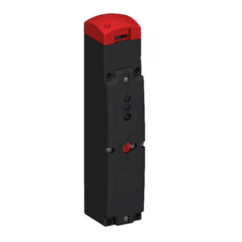
The Comepi safety limit switches are devices designed and made in
standards.
Installa�on precau�ons
system.
-
dirt from entering the opening when the start key is not inserted.
label.
operator when the door is open.
Use limits
This device complies with the following Direc�ves:
Approvals
Use and opera�on examples
shall not start.
Safety warnings
Use instructions – Electromagnetic safety limit switch 010 ISTR 03 SC 1221-02
ti
Technical data
Casing
Technopolymer casing
Rated implsive withstand voltage Uimp
,kV
Room temperatre dring operation
-C … +C
Conventional thermal crrent th
nvironmental designation
Type-enclosre
peronal crrent C-
V
V
Protection against electrical
shocks
Class (thermoplastic casing
pera
ti
onal crrent DC-
V
Degree of protection P
P (plastic casing
Maimm switching freency
cycleshor
Rated inslation voltage Ui
V
Load factor
.
Use categories according to
UL
Resistance between contacts
m
Connecting terminals
crews Mwith cable clamp
Terminal marking
ccording to C --
Dimensions of connecting cables*
. … .mm²
Mechanical drability
million operations
d
million operations

Use instructions – Electromagnetic safety limit switch 010 ISTR 03 SC 1221-02
The CE declaration of this product is available in the download section of website www.comepi.it or by writing to the following email address: t[email protected]
DDC 12 – Electromagnetic switches with separate actuator series FEP
Components / Tightening torques
Manual unlocking device,
also available with lock
Cover
Actuator
Solenoid
Micriswitch
3 threaded
inputs M20x1.5
A
B
F
C
DE
Fold
key
Flat
key
Dampet
fold key
Dampet
flat key
Swivel
key
Type of actuator
Head orienta�on
By following these steps it will be possible to orient the head of the FEP
maintaining correct opera�on.
- Unscrew the 4 screws Ø3 pozidriv1
- Remove the head from the body
- Check that the gasket on the pin is intact and well posi�oned
- Reposi�on the head in the desired direc�on
(0 °, 90 °, 180 °, 270 °) then press on it to anchor it to the body.
- Screw the head to the body, reusing the 4 screws Ø3 pozidriv1.
(�ghtening torque 0.8Nm)
- Repeat the func�onal tests before commissioning.
A
B
C
D
E
F
Closing
cover
Screws
Ø3
pozidriv1
Ø3
pozidriv1
Ø3
pozidriv1
Ø3
pozidriv1
M3
pozidriv1
M3
pozidriv1
Couple of
tightening
Recommended
Max
(Nm/lbin)
0.8/7
0.9/8
0.5/4.3
0.8/7
0.8/7
0.9/8
0.5/4.3
0.8/7
0.5/4.3
0.8/7
Manual
unlocking
Head
fastening
Microswitch
fastening
Microswitch Supply
terminals
Not removable
Factory sealed

Use instructions – Electromagnetic safety limit switch 010 ISTR 03 SC 1221-02
The CE declaraiton of this product is available in the download section of website www.comepi.it or by writing to the following email address: [email protected]
DDC 12 – Electromagnetic switches with separate actuator series FEP
Auxiliary release
The device can be equipped with two types of release auxiliary.
Auxiliary release via safety screw.
The arrow on the cover indicates the status of the device.
The release is ac�vated by unscrewing the safety screw and turning 180 °.
In order to avoid misuse of the func�on of release, the device is supplied
with the safety screw sealed with paint.
Auxiliary release with lock.
The release is ac�vated by inser�ng the key into the lock, then turning it
180 °.
The device is supplied complete key and dust seal.
Actuator installa�on precau�ons
Always use the cap
for the unused slot
Drawing 2D
Contact numbering

Use instructions – Electromagnetic safety limit switch 010 ISTR 03 SC 1221-02
The CE declaraiton of this product is available in the download section of website www.comepi.it or by writing to the following email address: [email protected]
DDC 12 – Electromagnetic switches with separate actuator series FEP
Definition of electrical
contacts
Other COMEPI Switch manuals