manuals.online logo
Brands
  1. Home
  2. •
  3. Brands
  4. •
  5. Comet Antenna
  6. •
  7. Antenna
  8. •
  9. Comet Antenna HFJ-350M User manual

Comet Antenna HFJ-350M User manual

Instruction Manual
MODEL
【 Features 】
● It is a 3-division structure that is convenient to carry.
● Telescopic antenna for multi-band HF to 50 MHz band, whose frequency can be easily changed by short plug.
● Round-shape solderless Terminal for counterpoise is included. (Stranded wire: 3.5 sq [AWG12] compatible)
【Product image】
accessories
Short plug
   Cautions on installation
◆ This product is not suitable for mobile use. Please do not set it on the vehicle and drive.
◆ If there are other antennas or obstacles such as buildings near this antenna, this will cause
SWR degradation and resonance frequency shift. In that case, please change the mounting
position of the antenna.
!
◆ Make sure that the connector of the connection cable and the antenna connector are of the
same type. If it is a different type, it can not be connected or it may be damaged.
HF-50MHz Portable Telescopic Antenna
For : 3.5 / 7 / 10 / 14 / 18 / 21 / 24 / 28 / 50 MHz
   Handling and operation precautions
!
Base Coil
with connector
Product configuration
3.5 MHz expansion coil
connection & Telescopic
element shortest
HFJ-350M
M-P (PL-259)
Connector
3.5MHz
Expansion coil
Telescopic
Element
Thank you for purchasing our products.
For your safety :
Read this manual carefully for proper handling and operation before using.
Keep this manual in a safe place for future reference.
【 Specifications 】
Antenna type : 1/4 λ base loading type antenna
Frequency : 3.5 / 7 / 10 / 14 / 18/ 21 / 24 / 28 / 50 MHz 9-Bands
Max.Input Power : 75W (SSB) [3.5MHz] , 100W (SSB) [7 - 50MHz]
Impedance : 50Ω
Length : Min. 370mm , Max. 1665mm
Weight : approx. 260g (included 3.5MHz expansion coil)
Antenna Connector : M-P (PL-259)
● When installing or removing the antenna or adjusting the element, be careful not to open your
eyes at the end of the rod.
● Do not touch the antenna during and immediately after transmission. The fever can cause burns.
● Tighten the fixing screws firmly so that there are no accidents.
● When extending the rod, always keep in mind that there are no obstacles in the height direction.
● Do not use it outdoors when it is wet, as it is not waterproof.
● Do not use when the surface is wet, and use completely dry.
◆ To use this product, capacitive coupling with grounding or counterpoise is required.
Note that if the ground capacitance is insufficient, the VSWR characteristics will deteriorate,
especially in the low frequency band, and there is a high possibility that adjustment will not be
possible.
◆ On the structure shortened by the loading coil, the tuning band is narrow. If you want to check
where the tuning frequency is, we recommend using an antenna analyzer such as CAA-500Mark II.
■ Connect a 3.5 MHz expansion coil to the upper thread of
the base coil and connect the telescopic element on it.
■ Adjust the frequency by adjusting the length of the
telescopic element without using a short plug.
【How to connect and adjust】
【 How to use 】
Up
and
down
short
position
change
Term. 5
The figure above shows that
terminals 0 and 5 are
shorted when using 50 MHz.
【50MHz】
If the frequency to be used repeatedly is decided, it is
recommended to write down the element length.
Notice : Since the number of turns of the loading coil is
increased by design, the tuning band is narrow and it may be
difficult to find the tuning frequency.
Standard value of adjustment length L
7 MHz :
10 MHz :
14 MHz :
750 mm960 mm 530 mm990 mm 1000 mm800 mm 950 mm
length L
( Min.approx.187mm - Max.approx.1266mm)
10-sections
Telescopic element
1070 mm(※)
18 MHz :
Attention : SWR may not fall depending on conditions such
as the grounding condition and the installation position of
the antenna. We recommend using an antenna tuner.
Amount of change per 1 cm
(standard value)
When using 3.5 MHz band
■ Connect the telescopic element directly to the upper
thread of the base coil without using a 3.5 MHz expansion
coil.
■ In the case of 7 MHz, do not use a short plug, but adjust the
length by adjusting the length of the telescopic element.
▲When using other than 7 MHz, use a short plug.
●Connection example
In case of 14 MHz Connect term.0 and term.2
28 MHz Connect term.0 and term.4
50 MHz Connect term.0 and term.5
When using 7 to 50 MHz band
For 3.5 MHz and 7 MHz,
Do not use short plugs.
Also, the 18 MHz band has a length of By changing
this, a resonance point appears at terminal 2 or 3.
3.5 MHz : 910 mm 21 MHz :
24 MHz :
28.5 MHz :
51 MHz :
7 MHz :
10 MHz :
14 MHz :
80 kHz/cm25 kHz/cm 100 kHz/cm40 kHz/cm 120 kHz/cm60 kHz/cm 100 kHz/cm
50 kHz/cm
18 MHz :
3.5 MHz : 20 kHz/cm 21 MHz :
24 MHz :
28.5 MHz :
51 MHz :
(※) Length when using terminal 3
3rd edition. Mar 2020. Printed in JAPAN.
Connect wire etc. to be
counterpoise here.
Stranded wire : 3.5SQ [AWG12]
Copyright (C) 2019 COMET CO.,LTD. All Rights Reserved.
■ Specifications or appearance is subject to change without notice.
COMET CO.,LTD.
4-18-2, Tsuji, Minami-ku, Saitama-shi, Saitama-Pref, 336-0026, JAPAN
TEL : 81-48-839-3132 / FAX : 81-48-839-3136
URL : https://www.comet-ant.co.jp (Japanese site)
   Caution
● This product is designed for amateur radio communication only.
● If a phenomenon that seems to be abnormal occurs during use, stop using it immediately
and check the antenna status.
● Check if the antenna connector fits into the radio connector.
● During continuous output, there is a possibility of element heat and deterioration of
SWR. In that case, please reduce the output or increase the output interval.
● Repairs and modifications by the customer themselves may cause damage.
● If the telescopic element is bent, it is impossible to repair. Please handle it carefully.
!
▼If you want to lower the tuning frequency, stretch the rod element.
▼If you want to increase the tuning frequency, shrink the rod element.
◆Shrink the element from the upper narrow part.
1. Make sure that the telescopic length and short between
terminals match the setting corresponding to the operating
frequency.
2. Firmly insert the antenna into the connector and screw it in
clockwise to connect.
3. Install the antenna as vertically as possible for better
communication.
4. Since one R-shaped solderless terminal is provided near the
connector, it is recommended to attach an polyvinyl chloride
insulated wire etc. to be a counterpoise. Since the length of
the counterpoise changes depending on the environment,
please prepare a longer one.
5. Check the SWR of the antenna by adjusting the telescopic
length, counterpoise length, and how the wires are arranged.
In particular, it may not be possible to adjust well in low
frequency bands such as 3.5MHz and 7MHz. In that case,
please consider using an antenna tuner separately.
(COMET CAT-300 is recommended.)
Term. 4
【28MHz】
Term. 3
Term. 2
Term. 1
Term. 0 (Common)
【10MHz】
【14 & 18MHz】
【18 , 21 & 24MHz】
If you use other than 3.5MHz and
7MHz, use a short plug here.
Connect the lower side.
Standard length of counterpoise line
3.5MHz: 20m , 7MHz: 12m
* Depending on conditions, longer lines
It may be necessary.

Other Comet Antenna Antenna manuals

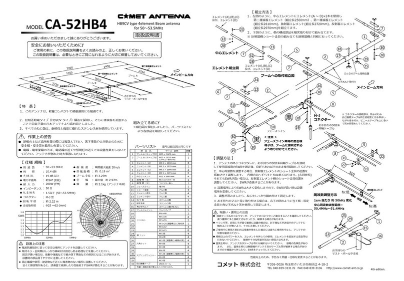
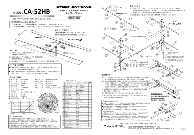
Comet Antenna CA-52HB4 User manual

Comet Antenna

Comet Antenna CA-52HB4 User manual

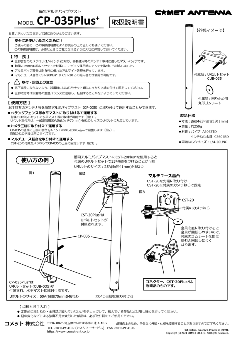
Comet Antenna CP-035Plus User manual

Comet Antenna

Comet Antenna CP-035Plus User manual

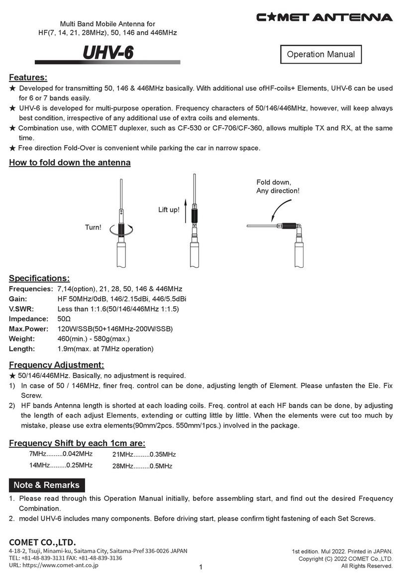
Comet Antenna UHV-6 User manual

Comet Antenna

Comet Antenna UHV-6 User manual

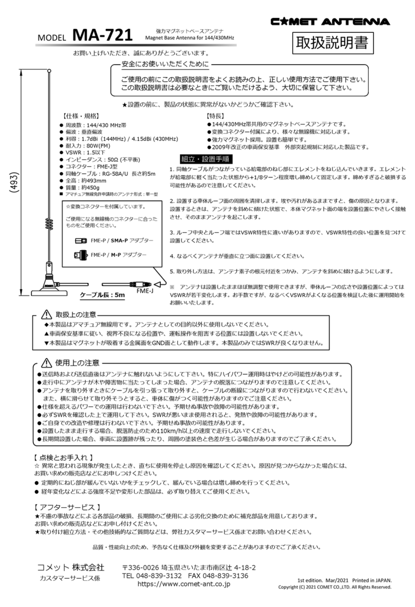
Comet Antenna MA-721 User manual

Comet Antenna

Comet Antenna MA-721 User manual

Comet Antenna PI7100 User manual

Comet Antenna

Comet Antenna PI7100 User manual

Popular Antenna manuals by other brands

Naxa NAA-303 manual 

Naxa

Naxa NAA-303 manual 

Raymarine STV37 Installation & operation instructions

Raymarine

Raymarine STV37 Installation & operation instructions

KVH Industries TracVision M9 Replacement instructions

KVH Industries

KVH Industries TracVision M9 Replacement instructions

COBHAM SAILOR 60 GX-R2 4.5 W installation manual

COBHAM

COBHAM SAILOR 60 GX-R2 4.5 W installation manual

TERK Technologies HDR-I - TERK - HD Radio Antenna user guide

TERK Technologies

TERK Technologies HDR-I - TERK - HD Radio Antenna user guide

QuickSAT QS65 user manual

QuickSAT

QuickSAT QS65 user manual

PK's Loop Antennas C-DIPOLE-40m installation guide

PK's Loop Antennas

PK's Loop Antennas C-DIPOLE-40m installation guide

M2 Antenna Systems 418CP30 manual

M2 Antenna Systems

M2 Antenna Systems 418CP30 manual

Alaris OMNI-A0092 Technical reference manual

Alaris

Alaris OMNI-A0092 Technical reference manual

Kathrein AVH 06 manual

Kathrein

Kathrein AVH 06 manual

Ubiquiti AM-V2G-Ti quick start guide

Ubiquiti

Ubiquiti AM-V2G-Ti quick start guide

M2 Antenna Systems 20M5-125 manual

M2 Antenna Systems

M2 Antenna Systems 20M5-125 manual

Solid Signal Xtreme Signal HDB2X Assemble

Solid Signal

Solid Signal Xtreme Signal HDB2X Assemble

DX Antenna DTA5000 instruction manual

DX Antenna

DX Antenna DTA5000 instruction manual

Diamond Antenna WD330S operating instructions

Diamond Antenna

Diamond Antenna WD330S operating instructions

Novatel GPS-704-X user guide

Novatel

Novatel GPS-704-X user guide

TRENDnet TEW-AI86D user guide

TRENDnet

TRENDnet TEW-AI86D user guide

Ubiquiti AF-5G-OMT-S45 quick start guide

Ubiquiti

Ubiquiti AF-5G-OMT-S45 quick start guide

manuals.online logo
manuals.online logoBrands
  • About & Mission
  • Contact us
  • Privacy Policy
  • Terms and Conditions

Copyright 2025 Manuals.Online. All Rights Reserved.