manuals.online logo
Brands
  1. Home
  2. •
  3. Brands
  4. •
  5. Comet
  6. •
  7. Antenna
  8. •
  9. Comet GP-285 User manual

Comet GP-285 User manual

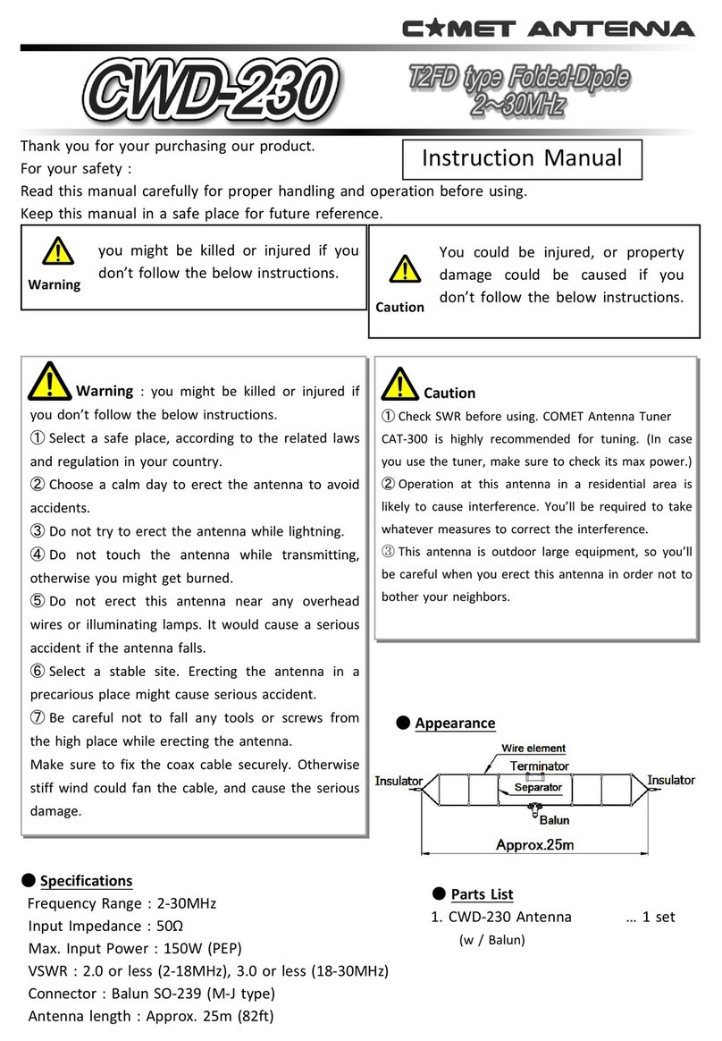
Instruction Manual
MODEL
Thank you for purchasing our products.
For your safety :
Read this manual carefully for proper handling and operation before using.
Keep this manual in a safe place for future reference.
GP-285
【Specifications】
Frequency band : 135 - 175 MHz (by adjustment of element length)
Antenna type : 5/8 λ 2-stage collinear antenna
Gain : 5.15 dBi
Polarization : Vertical (omnidirectional in horizontal plane)
VSWR : 1.5 or less
Band with VSWR 1.5 or less : 2 MHz (at 135 MHz) , 4 MHz (at 175 MHz)
Band with VSWR 2.0 or less : 4 MHz (at 135 MHz) , 8 MHz (at 175 MHz)
Max.Input Power : 500 W (CW)
Lightning protection structure : DC Grounded
Overall length : Max. 3.34 m (135 MHz) , Min. 3.0 m (175 MHz)
Wind speed : Max. 50 m / s
Wind receiving load : Max. 142 N
Wind receiving area : Max. 0.115 m2
Weight : approx. 2.3 kg (except mount bracket)
Connector : SO-239 (M-J)
【Features】
●This product is a 5/8λ 2-stage high gain GP antenna.
●By adjusting the element length, VHF band amateur band (144-148 MHz) was included.
It can be used in the range of 135 to 175 MHz.
●High withstand input 500 W antenna.
④ Radial element (L:430mm) … 8pcs.
COMET CO.,LTD.
4-18-2, Tsuji, Minami-ku, Saitama-shi, Saitama-Pref, 336-0026, JAPAN
TEL : 81-48-839-3131 / FAX : 81-48-839-3136
URL : http://www.comet-ant.co.jp/english Copyright (C) 2019 COMET CO.,LTD. All Rights Reserved.
Jan.2019 1st edition. Printed in JAPAN.
VHF Band
5/8 λ 2-stage Collinear Antenna
First of all, please check whether
there are parts as per the parts list.
⑦ Radial clamp … 8pcs.
② Bottom element (L:1760mm) … 1pc.
⑤ Hose clamp (Small) … 1pc.
⑥ Hose clamp (Large) … 1pc.
① Top element A (w/ Feeding section) … 1 set
③ Top element B (L:840mm) … 1 pc.
⑧ Hex Bolt (No.10x24 5/8")… 32pcs.
⑨ Tooth Washer [Internal] (No.10)… 32pcs.
⑩ Hex Nut (No.10x24) … 32pcs.
Parts List
Assembling the bottom element part
1. Four radial clamps and four radial pipes become
one radial unit.
Temporarily assemble as shown in the fig.1 , and
combine it up and down two units.
Fig.1
Set of Radial unit.
⑪ U-Bolt … 2pcs.
⑫ Mount Bracket … 2pcs.
⑬ Hex Bolt (M6x30) … 2pcs.
⑭ Spring Washer (M6) … 6pcs.
⑮ Hex Nut (M6) … 6pcs.
④ Radial element
⑦ Radial clamp
⑧ Hex Bolt
⑨ Tooth Washer
⑩ Hex Nut
- Page4 - - Page1 -
【Maintenance】
■ If any unusual situation happens, stop using immediately and ask the local agent you purchased this product.
■ Confirm if the product works normally before operating.
■ Be sure to change the parts which have strength poverty or deformation across the ages etc.
!
PRECAUTIONS for Operation
●Do not touch the antenna while transmitting, otherwise you would get burned.
●Do not touch the antenna or coax cables while lightning. Checking VSWR after lightning is highly recommended.
●Do not use this antenna outside its specification. Failure to follow this would damage the antenna.
●Make sure to adjust the antenna in a right way. Higher VSWR could cause the performance degradation.
●Never attempt to fix or modify this antenna by yourself.
Specifications or appearance is subject to change without notice.
   PRECAUTIONS for Installation
● Wearing a safety hat and a life line during installing on a roof top or any high places is highly recommended.
● Erect this antenna in a safe place Check if the Cable Connector fits into the Antenna Connector.
● Make sure all nuts, bolts and screws are securely tightened. Failure to follow this would cause a serious
accident or performance degradation.
● Check if waterproofing at each connection is appropriately done. If not, it would cause short-circuit and/or
corrosion.
● Do not erect this antenna near any electrical power lines, steel towers and/or buildings. Such objects would
cause performance degradation.
!
Vertical Beam Pattern Image
VSWR
VSWR Reference data at 144MHz
150MHz
2.0
Length : 1325 mm
Length : 870 mm
A
B
145MHz
140MHz
1.8
1.6
1.5
1.4
1.3
1.2
1.1
1.0
Length B
2. Pass one set of radial unit through the bottom pipe and position and fix it according to the
frequency to be used. (See frequency adjustment chart)
3. Pass the other radial unit through the bottom pipe, and fix the lower radial unit at the
position where the height of the upper end of the radial clamp matches the lower end of the
pipe of the upper radial unit. (See Fig.5)
At this time, the radial pipe of the upper and lower radial unit should be shifted by 45 °.
Unit A
Unit B
Unit A
Unit A
Unit A
Unit A
Unit B
Unit B
Unit B
Unit B
View from the top side
Assembling the Top element part
1. Insert the Top element B into the Top element A, adjust the length
according to the frequency to be used, tighten the hose clamp and fix.
(See frequency adjustment chart)
2. Thread the coaxial cable from the bottom of the bottom pipe and take
out the connector at the top from the top. Insert the connector of the
power supply part into the connector pulled out, waterproof the
fitting part, and then insert the connector part into the bottom pipe.
3. Tighten the hose clamp to fix.
Length A
⑤ Hose clamp (Small)
Installation of Mount bracket
1. Pass through 2 sets of mounting brackets from the bottom of the bottom pipe, fix the
distance between the upper and lower brackets to about 150 to 180 mm and fix it in the
same direction. The position to fix the bracket should be within 250 mm from the lower end.
2. Fix the mounting bracket part to the mast. The mast diameter that can be installed is in the
range of Φ 30 to 62 mm.
Antenna Hold Area
① Top element A
w/ Feeding section
③ Top element B
⑥ Hose clamp (Large)
Coax.Cable
w/ PL-259(M-P) Connector
Frequency Adjustment Chart
A is the length of the upper side from the feeding part.
B is the length from the upper end of the bottom pipe to the upper tip of radial clamp.
⑪ U-Bolt
⑫ Mount Bracket ⑬ Hex Bolt
⑭ Spring Washer (M6)
⑮ Hex Nut (M6)
A
B
About the installation position of the antenna
It is desirable that there are no obstacle metal around the antenna , but when
installing it on the side of the tower, please keep it away by at least 60 cm.
Antenna Mast [Φ30 -62mm]
- Page2 - - Page3 -
Fig.2
Radial element
Fig.3
Mount bracket
Fig.4
Top element
Fig.5
Element length tuning
A
B
Align the position of the lower radial clamp
Assembling of the antenna is completed if the length is adjusted
according to the operating frequency.

Other Comet Antenna manuals

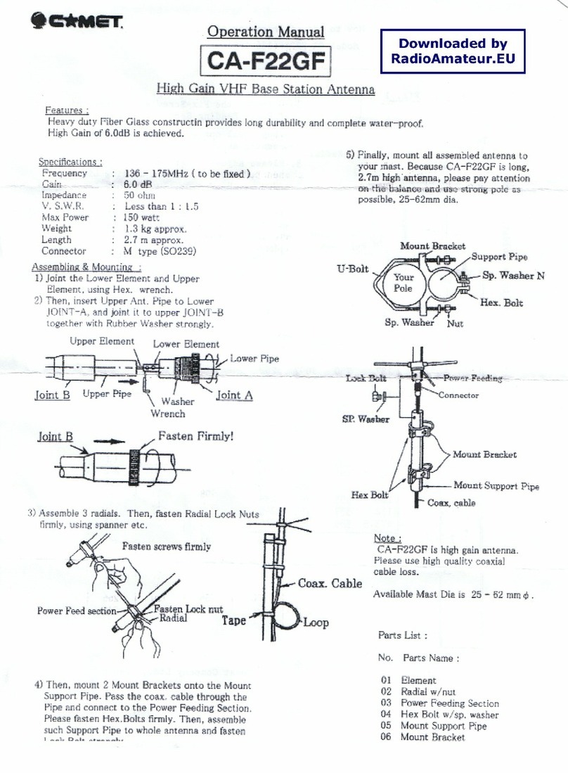
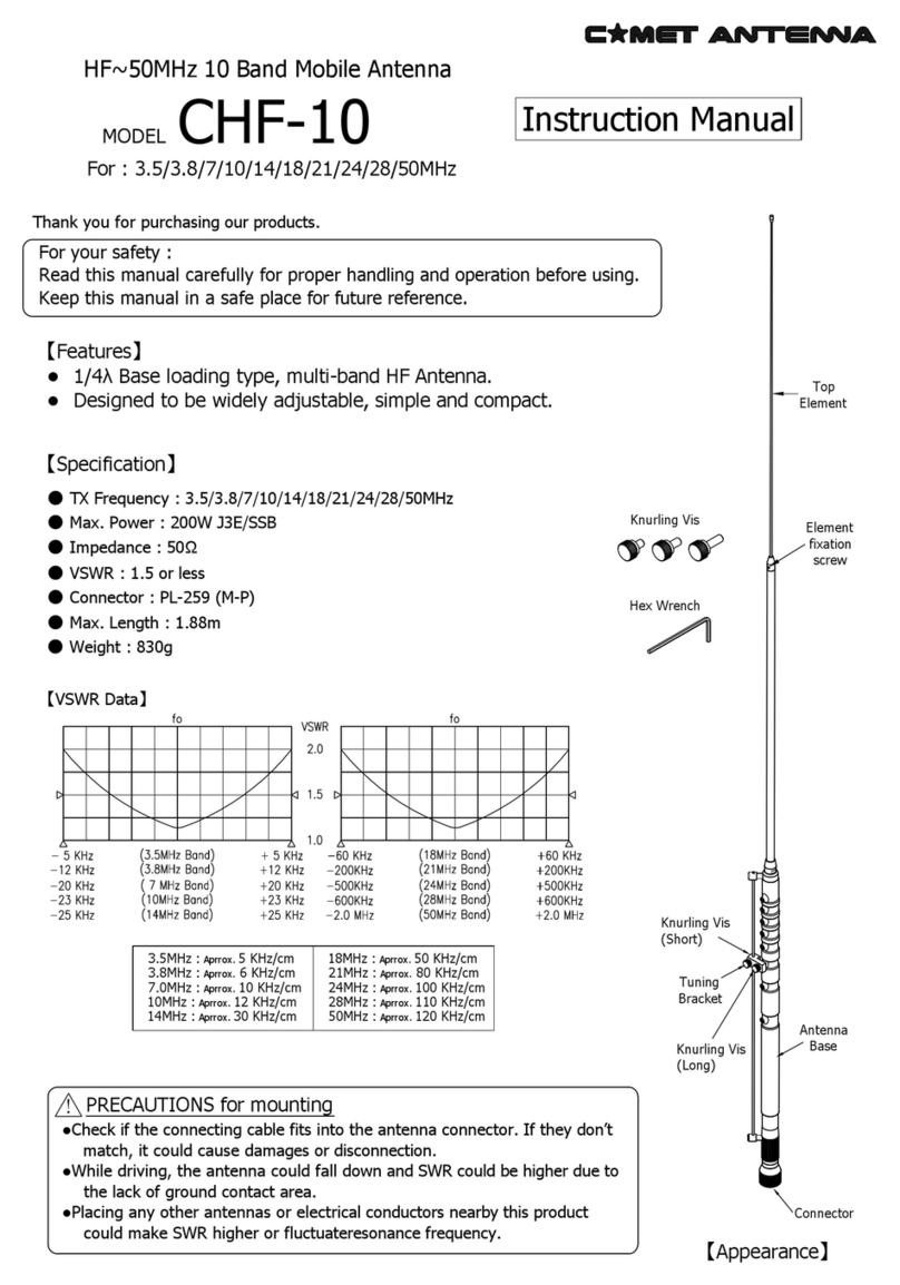
Comet CHF-10 User manual

Comet

Comet CHF-10 User manual

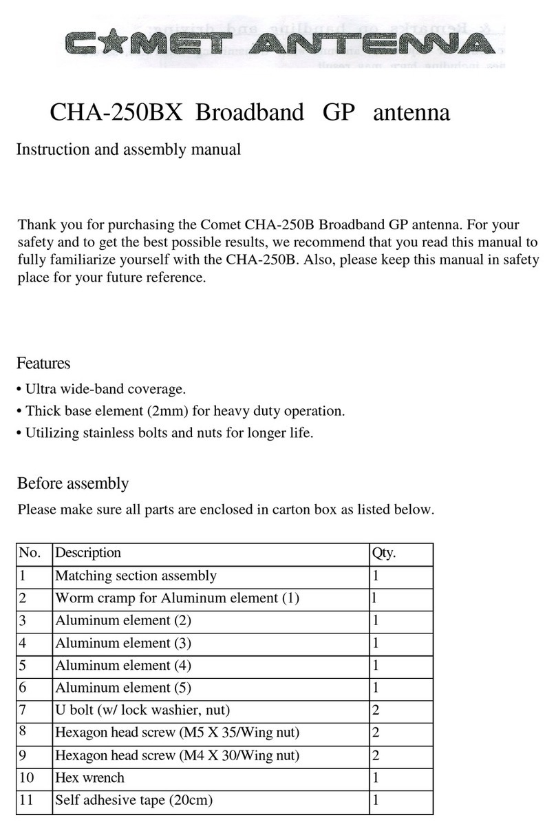
Comet CHA-250BX User manual

Comet

Comet CHA-250BX User manual

Comet CA-F72GF User manual

Comet

Comet CA-F72GF User manual

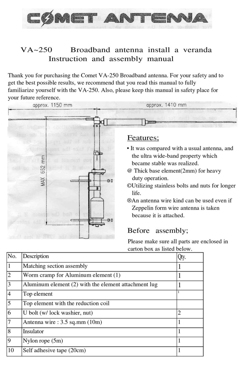
Comet VA-250 User manual

Comet

Comet VA-250 User manual

Comet H-422 User manual

Comet

Comet H-422 User manual

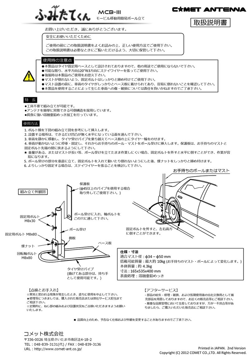
Comet MCB-III User manual

Comet

Comet MCB-III User manual

Comet UHV-9 User manual

Comet

Comet UHV-9 User manual

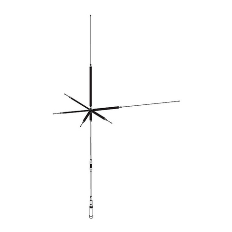
Comet CA-F22GF User manual

Comet

Comet CA-F22GF User manual

Comet CHA-250BX User manual

Comet

Comet CHA-250BX User manual

Comet CAT-300 User manual

Comet

Comet CAT-300 User manual

Comet Super Beam CSB790A User manual

Comet

Comet Super Beam CSB790A User manual

Comet CWD-230 User manual

Comet

Comet CWD-230 User manual

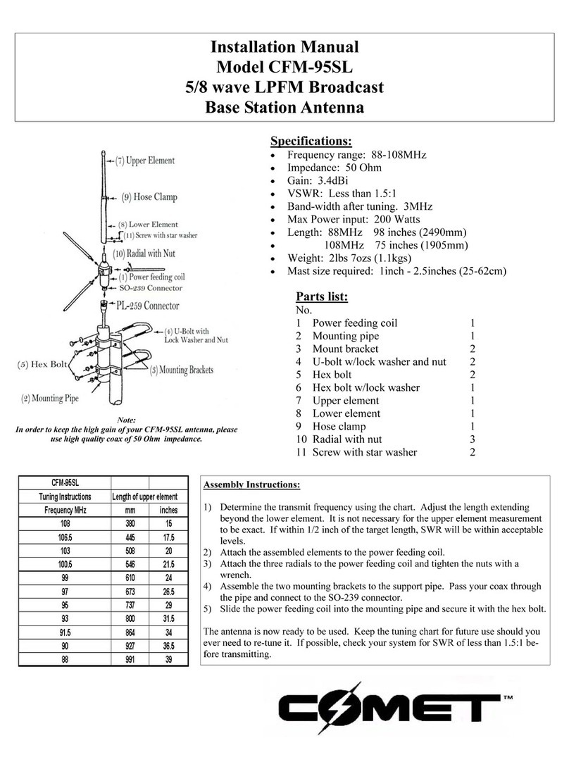
Comet CFM-95SL User manual

Comet

Comet CFM-95SL User manual

Popular Antenna manuals by other brands

Phasemaster CD910-71-75 Series quick start guide

Phasemaster

Phasemaster CD910-71-75 Series quick start guide

Matsing MS-18H90 instruction manual

Matsing

Matsing MS-18H90 instruction manual

TRENDnet TEW-AI77OB - Duo 7dBi Indoor Omni Directional... Quick installation guide

TRENDnet

TRENDnet TEW-AI77OB - Duo 7dBi Indoor Omni Directional... Quick installation guide

Antennas4Less SignaLoop HF-319 manual

Antennas4Less

Antennas4Less SignaLoop HF-319 manual

TERK Technologies AM/FM Tower Powered Indoor Antenna owner's manual

TERK Technologies

TERK Technologies AM/FM Tower Powered Indoor Antenna owner's manual

MFJ IntelliTuner -991 instruction manual

MFJ

MFJ IntelliTuner -991 instruction manual

Nippon Antenna AU8F instruction manual

Nippon Antenna

Nippon Antenna AU8F instruction manual

M2 Antenna Systems EB-144/RK2M manual

M2 Antenna Systems

M2 Antenna Systems EB-144/RK2M manual

Clas Ohlson E560E156N quick start guide

Clas Ohlson

Clas Ohlson E560E156N quick start guide

Sennheiser A 3700 Instructions for use

Sennheiser

Sennheiser A 3700 Instructions for use

Kenwood CX-DAB1 installation manual

Kenwood

Kenwood CX-DAB1 installation manual

Universat Italia Services AD511-2 manual

Universat Italia Services

Universat Italia Services AD511-2 manual

GME MB042 quick start guide

GME

GME MB042 quick start guide

Winegard RZ-7500 user guide

Winegard

Winegard RZ-7500 user guide

OmniMetrix TrueGuard Pro installation guide

OmniMetrix

OmniMetrix TrueGuard Pro installation guide

Feig Electronic OBID i-scan ID ISC.ANTU250/250 Montage, installation

Feig Electronic

Feig Electronic OBID i-scan ID ISC.ANTU250/250 Montage, installation

Roadpro D3201 Installation and instruction manual

Roadpro

Roadpro D3201 Installation and instruction manual

TechniSat DIGIDISH 33 installation manual

TechniSat

TechniSat DIGIDISH 33 installation manual

manuals.online logo
manuals.online logoBrands
  • About & Mission
  • Contact us
  • Privacy Policy
  • Terms and Conditions

Copyright 2025 Manuals.Online. All Rights Reserved.