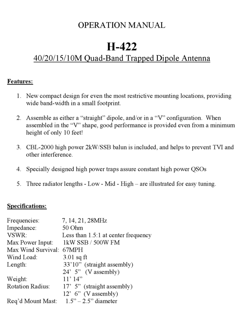
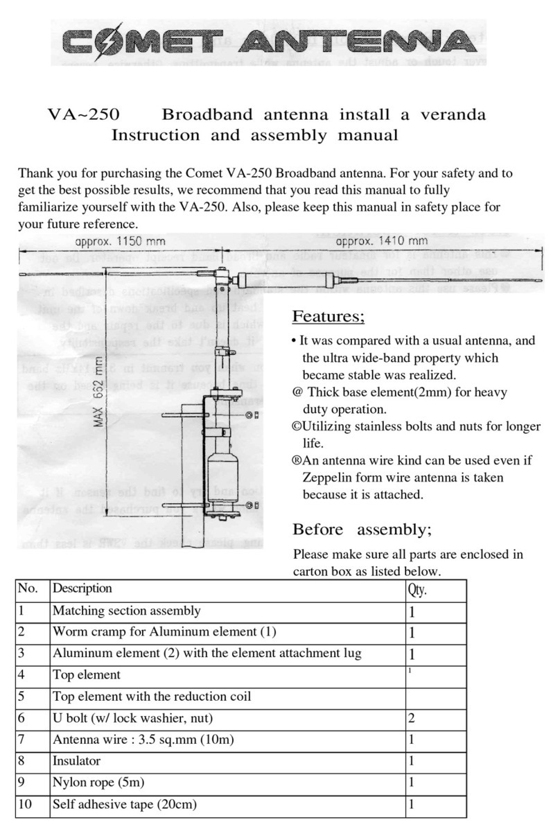
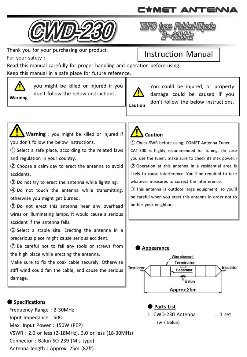
Comet UHV-9 User manual

1
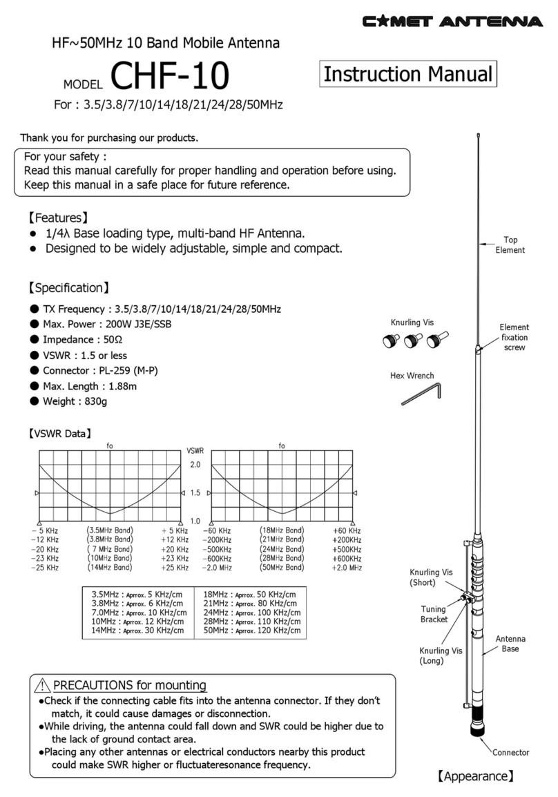
HF ( 3.5, 7, 14, 18, 21, 28MHz )
50MHz , 144MHz & 430MHz 9-Bands Antenna
s
For your safety :
Beforeassembling
cs
Parts Name Qty.
Main antenna (w/ extended element)1 set
L-3.5 Coil
7MHz Spare element φ1.5×550mm 1
4
Hex. wrench Opposite side 2 mm 1
Hex. wrench Opposite side 2.5mm1
【Features】
● s
●ft
e
ti
●Witrecghnistentvith
thentenn
● gegRS-tctence
succ
Externalview
(Exampleof9-bandoperation)
Frequency Band 3.5 MHz 7 MHz 14 MHz 18 MHz 21 MHz 28 MHz 50 MHz 144 MHz 430 MHz
Antenna Type × 2
Gain
Impedance
VSWR
Max. Input Power
Connector
Length
Weight
【Standardspecifications】
COMET Co., LTD.
UHV-9
MODEL
Tip element included
φ1.5×87mm14〜28MHz Spare element
L-7 Coil Tip element included
L-14 Coil Tip element included
L-18 Coil Tip element included
L-21 Coil Tip element included
L-28 Coil Tip element included
Note1. Spare elements for 3.5 MHz are not included.
Note2. Spare elements are longer than standard.
TttreJAPAN
trcret
gtrvn
1 set
1 set
1 set
1 set
1 set
1 set

2
Precautionsforhandlingandoperation
③
①
【】
☆
②

3
Lock nut
Element bracket
Upper element
※Note
Lock nut
L-3.5 etc...
HF band coil
unfasten & remove
Notes on installa
stallingaconnectccconnector
ntenna.
ere diereneaconnected or maged.
rantenna base tfence. If it is used in a loosened state, it maown b
antenna or dropped bstrong wind.
Also, be sure to aradial or counterpoise tntenna base securelround area is
nt due to poor contact, VSen does not improve.
It is not necessarto connecoils.
Acoil rou want to operat
advantages of easier adjustment and less vibrantenna.
[HF band coil element moun�ng]
1) When using 4 bands
(1) Trnt to loosen it
and removrnt.
* Please keep it in a safe place.
(2) Screred HF band coil intnt seat
tt
☆rnt is screwed in a
nat it does not fall o.
2) When using 5 to 9 bands
ow set scrent brackeaer
(opposite side 2mm) and remove it frnt.
(2) Trnt to loosen it, and removrnt and lock nut
wakeep it in a safe place as it will not be used)
aracket intnt.
* Maave been inserted ant.
nt seat intnt and
tow set scre
element seat t
racket unnt bracket,
and tigtow set scre
aerte side 2.5mm) t
(6) Acr
ou want to use tracket
lock nut to secure it.
(7) Screcower fr
ou want to use intnt bracketen
to secure it.
※Note : Aow frcoil (3.5MHz or 7MHz)
tnt bracket will rra
rnt
Element bracket
Upper element
Side bracket
Hollow set screw
Hollow set screw

4
【UHV-9adjustmentmethod】
Caution
※:
()fo
※
※
L
Non
rccr
Srvcrc
TrFry rc
rrVSvb
cyb ATATAT
by RSrcy
by cr
nef
c
vr
r
Yc y
ryrr
・・・
rrb
crVScr
b c r
rrrrcr
cSr
rcrr
・bc
bb yr
F
efev rVS
VSy cvti
r
vr
rvv
v
VSr
k
CF
coc
CF
coc
E
conneco
E
conneco
Fcnnoo
n
ecW
5
50,144,430MHz
☆Coil installa�on image and SWR characteris�cs example when using in 3 bands or 4 bands
It is possible to operate up to 9 bands by adding each HF band coil
to the side bracket.
4 to 9 bands
examples.
28,50,144,430MHz 21,50,144,430MHz
1.0
1.5
2.0
440 445 450
Freq.(MHz)
SWR
1.0
1.5
2.0
145 146 147
Freq.(MHz)
SWR
1.0
1.5
2.0
50 52 54
Freq.(MHz)
SWR
51 53
1.0
1.5
2.0
440 445 450
Freq.(MHz)
SWR
1.0
1.5
2.0
145 146 147
Freq.(MHz)
SWR
1.0
1.5
2.0
50 52 54
Freq.(MHz)
SWR
51 53
1.0
1.5
2.0
21 21.225 21.45
Freq.(MHz)
SWR
1.0
1.5
2.0
440 445 450
Freq.(MHz)
SWR
1.0
1.5
2.0
145 146 147
Freq.(MHz)
SWR
1.0
1.5
2.0
50 52 54
Freq.(MHz)
SWR
51 53
1.0
1.5
2.0
28 29 30
Freq.(MHz)
SWR
28.5 29.5
28MHz Coil (L-28)
28MHz Tip element
Element length Approx. 75mm
Element bracket
Auxiliary element
Upper element
50MHz choke coil
Bending mechanism
Middle element
Element length Approx. 80mm
See the table on page 4 for the �p
element length L of each HF band coil.
Please note that depending on the
combina�on of each band coil, there are
bands that are difficult to improve SWR.
Same as the leftre

6
18, 50, 144, 430MHz 14, 50, 144, 430MHz
1.0
1.5
2.0
440 445 450
Freq.(MHz)
SWR
1.0
1.5
2.0
145 146 147
Freq.(MHz)
SWR
1.0
1.5
2.0
50 52 54
Freq.(MHz)
SWR
51 53
1.0
1.5
2.0
18.068 18.110 18.168
Freq.(MHz)
SWR
1.0
1.5
2.0
440 445 450
Freq.(MHz)
SWR
1.0
1.5
2.0
145 146 147
Freq.(MHz)
SWR
1.0
1.5
2.0
50 52 54
Freq.(MHz)
SWR
51 53
1.0
1.5
2.0
14 14.175
14.350
Freq.(MHz)
SWR
Element bracket
Upper element
ere

7
7, 50, 144, 430MHz
3.5, 50, 144, 430MHz
1.0
1.5
2.0
440 445 450
Freq.(MHz)
SWR
1.0
1.5
2.0
145 146 147
Freq.(MHz)
SWR
1.0
1.5
2.0
50 52 54
Freq.(MHz)
SWR
51 53
1.0
1.5
2.0
7 7.10 7.20
Freq.(MHz)
SWR
1.0
1.5
2.0
440 445 450
Freq.(MHz)
SWR
1.0
1.5
2.0
145 146 147
Freq.(MHz)
SWR
1.0
1.5
2.0
50 52 54
Freq.(MHz)
SWR
51 53
1.0
1.5
2.0
3.5 3.5375
3.575
Freq.(MHz)
SWR
Element bracket
Upper element
element
ere

8
21, 28, 50 144, 430MHz
18, 28, 50, 144, 430MHz
1.0
1.5
2.0
440 445 450
Freq.(MHz)
SWR
1.0
1.5
2.0
145 146 147
Freq.(MHz)
SWR
1.0
1.5
2.0
50 52 54
Freq.(MHz)
SWR
51 53
1.0
1.5
2.0
28 29 30
Freq.(MHz)
SWR
28.5 29.5
1.0
1.5
2.0
18.068 18.110
18.168
Freq.(MHz)
SWR
1.0
1.5
2.0
440 445 450
Freq.(MHz)
SWR
1.0
1.5
2.0
145 146 147
Freq.(MHz)
SWR
1.0
1.5
2.0
50 52 54
Freq.(MHz)
SWR
51 53
1.0
1.5
2.0
21 21.225 21.45
Freq.(MHz)
SWR
1.0
1.5
2.0
28 29 30
Freq.(MHz)
SWR
28.5 29.5
☆Appearance diagram of coil installa�on and SWR characteris�cs example when using 5 bands ☆
Element bracket
Side bracket
50MHz choke coil
Lower element
Middle element
Same as the lere
Element bracket

9
14, 28, 50, 144, 430MHz 7, 28, 50, 144,430MHz
1.0
1.5
2.0
440 445 450
Freq.(MHz)
SWR
1.0
1.5
2.0
145 146 147
Freq.(MHz)
SWR
1.0
1.5
2.0
50 52 54
Freq.(MHz)
SWR
51 53
1.0
1.5
2.0
28 29 30
Freq.(MHz)
SWR
28.5 29.5
1.0
1.5
2.0
7 7.10 7.20
Freq.(MHz)
SWR
1.0
1.5
2.0
440 445 450
Freq.(MHz)
SWR
1.0
1.5
2.0
145 146 147
Freq.(MHz)
SWR
1.0
1.5
2.0
50 52 54
Freq.(MHz)
SWR
51 53
1.0
1.5
2.0
14 14.175 14.350
Freq.(MHz)
SWR
1.0
1.5
2.0
28 29 30
Freq.(MHz)
SWR
28.5 29.5
Element bracket
Side bracket
50MHz choke coil
70cm band
Phase shier
Lower element
Middle element
Same as the lere
Element bracket

10
3.5, 28, 50, 144, 430MHz 18, 21, 50, 144, 430MHz
1.0
1.5
2.0
440 445 450
Freq.(MHz)
SWR
1.0
1.5
2.0
145 146 147
Freq.(MHz)
SWR
1.0
1.5
2.0
50 52 54
Freq.(MHz)
SWR
51 53
1.0
1.5
2.0
3.5 3.5375
3.575
Freq.(MHz)
SWR
1.0
1.5
2.0
28 29 30
Freq.(MHz)
SWR
28.5 29.5
1.0
1.5
2.0
440 445 450
Freq.(MHz)
SWR
1.0
1.5
2.0
145 146 147
Freq.(MHz)
SWR
1.0
1.5
2.0
50 52 54
Freq.(MHz)
SWR
51 53
1.0
1.5
2.0
18.068 18.110
18.168
Freq.(MHz)
SWR
1.0
1.5
2.0
21 21.225 21.45
Freq.(MHz)
SWR
Element bracket
Side bracket
50MHz choke coil
70cm band
Phase shier
Lower element
Middle element
Same as the lere
Element bracket

11
14, 21, 50, 144, 430MHz 7, 21, 50, 144, 430MHz
1.0
1.5
2.0
440 445 450
Freq.(MHz)
SWR
1.0
1.5
2.0
145 146 147
Freq.(MHz)
SWR
1.0
1.5
2.0
50 52 54
Freq.(MHz)
SWR
51 53
1.0
1.5
2.0
7 7.10 7.20
Freq.(MHz)
SWR
1.0
1.5
2.0
21 21.225 21.45
Freq.(MHz)
SWR
1.0
1.5
2.0
440 445 450
Freq.(MHz)
SWR
1.0
1.5
2.0
145 146 147
Freq.(MHz)
SWR
1.0
1.5
2.0
50 52 54
Freq.(MHz)
SWR
51 53
1.0
1.5
2.0
14 14.175 14.350
Freq.(MHz)
SWR
1.0
1.5
2.0
21 21.225 21.45
Freq.(MHz)
SWR
Side bracket
50MHz choke coil
70cm band
Phase shier
Lower element
Middle element
Upper element
Same as the lere
Element bracket
Element bracket

12
3.5, 21, 50, 144, 430MHz 14, 18, 50, 144, 430MHz
1.0
1.5
2.0
440 445 450
Freq.(MHz)
SWR
1.0
1.5
2.0
145 146 147
Freq.(MHz)
SWR
1.0
1.5
2.0
50 52 54
Freq.(MHz)
SWR
51 53
1.0
1.5
2.0
3.5 3.5375
3.575
Freq.(MHz)
SWR
1.0
1.5
2.0
21 21.225 21.45
Freq.(MHz)
SWR
1.0
1.5
2.0
440 445 450
Freq.(MHz)
SWR
1.0
1.5
2.0
145 146 147
Freq.(MHz)
SWR
1.0
1.5
2.0
50 52 54
Freq.(MHz)
SWR
51 53
1.0
1.5
2.0
14 14.175
14.350
Freq.(MHz)
SWR
1.0
1.5
2.0
18.068 18.110
18.168
Freq.(MHz)
SWR
3.5MHz Coil (L-3.5)
3.5MHz Tip element
Element length Approx. 503mm
21MHz Tip element
Element length Approx. 80mm
21MHz Coil (L-21)
ere
14MHz Coil (L-14)
14MHz Tip element
Element length Approx. 80mm
18MHz Tip element
Element length Approx. 75mm
18MHz Coil (L-18)
er
Middle element
Upper element

13
7, 18, 50, 144, 430MHz 3.5, 18, 50, 144, 430MHz
1.0
1.5
2.0
440 445 450
Freq.(MHz)
SWR
1.0
1.5
2.0
145 146 147
Freq.(MHz)
SWR
1.0
1.5
2.0
50 52 54
Freq.(MHz)
SWR
51 53
1.0
1.5
2.0
3.5 3.5375 3.575
Freq.(MHz)
SWR
1.0
1.5
2.0
18.068 18.110 18.168
Freq.(MHz)
SWR
1.0
1.5
2.0
440 445 450
Freq.(MHz)
SWR
1.0
1.5
2.0
145 146 147
Freq.(MHz)
SWR
1.0
1.5
2.0
50 52 54
Freq.(MHz)
SWR
51 53
1.0
1.5
2.0
7 7.10 7.20
Freq.(MHz)
SWR
1.0
1.5
2.0
18.068 18.110 18.168
Freq.(MHz)
SWR
7MHz Coil (L-7)
7MHz Tip element
Element length Approx. 503mm
Element length Approx. 75mm
18MHz Coil (L-18)
Middle element
Upper element
18MHz Tip element
3.5MHz Coil (L-3.5)
3.5MHz Tip element
Element length Approx. 503mm
Element length Approx. 75mm
18MHz Coil (L-18)
18MHz Tip element
ere

14
3.5, 14, 50, 144, 430MHz
7, 14, 50, 144, 430MHz
1.0
1.5
2.0
440 445 450
Freq.(MHz)
SWR
1.0
1.5
2.0
145 146 147
Freq.(MHz)
SWR
1.0
1.5
2.0
50 52 54
Freq.(MHz)
SWR
51 53
1.0
1.5
2.0
3.5 3.5375 3.575
Freq.(MHz)
SWR
1.0
1.5
2.0
14 14.175 14.350
Freq.(MHz)
SWR
1.0
1.5
2.0
440 445 450
Freq.(MHz)
SWR
1.0
1.5
2.0
145 146 147
Freq.(MHz)
SWR
1.0
1.5
2.0
50 52 54
Freq.(MHz)
SWR
51 53
1.0
1.5
2.0
7 7.10 7.20
Freq.(MHz)
SWR
1.0
1.5
2.0
14 14.175 14.350
Freq.(MHz)
SWR
7MHz Coil (L-7)
7MHz Tip element
Element length Approx. 503mm
Element length Approx. 80mm
14MHz Coil (L-14)
14MHz Tip element
3.5MHz Coil (L-3.5)
3.5MHz Tip element
Element length Approx. 503mm
Tip
Element length Approx. 80mm
14MHz Coil (L-14)
14MHz Tip element
Middle element
Upper element

15
3.5, 7, 50, 144, 430MHz - 5 Bands
50MHz choke coil
1.0
1.5
2.0
440 445 450
Freq.(MHz)
SWR
1.0
1.5
2.0
145 146 147
Freq.(MHz)
SWR
1.0
1.5
2.0
50 52 54
Freq.(MHz)
SWR
51 53
1.0
1.5
2.0
77.10 7.20
Freq.(MHz)
SWR
1.0
1.5
2.0
3.5 3.5375 3.575
Freq.(MHz)
SWR
Middle element
7MHz Tip element

16
☆External view of coil installa�on and example of SWR characteris�cs when used with 9 bands
3.5, 7, 14, 18, 21, 28, 50, 144, 430MHz - 9 Bands
1.0
1.5
2.0
440 445 450
Freq.(MHz)
SWR
1.0
1.5
2.0
145 146 147
Freq.(MHz)
SWR
1.0
1.5
2.0
50 52 54
Freq.(MHz)
SWR
51 53
1.0
1.5
2.0
21 21.225 21.45
Freq.(MHz)
SWR
1.0
1.5
2.0
28 29 30
Freq.(MHz)
SWR
28.5 29.5
1.0
1.5
2.0
18.068 18.110 18.168
Freq.(MHz)
SWR
1.0
1.5
2.0
14 14.175 14.350
Freq.(MHz)
SWR
1.0
1.5
2.0
7 7.10 7.20
Freq.(MHz)
SWR
1.0
1.5
2.0
3.5 3.5375 3.575
Freq.(MHz)
SWR
About moun�ng each element
If itis installed near the horizontallyinstalled antenna
element and parallel to the wall, VSWR may notbe
improved.
In that case, try changing the moun�ng posi�on of each
band coil.
Exampleofmountingeachelement [Viewfromabove]
When opera�ng in 9 bands, the lateral
extension of the 7 MHz band element
becomes longer. Please be careful about
contact accidents.
Please note that some bands have difficulty in reducing
SWR due to mutual interference between the bands.
For bands where SWR is hardto improve,we recommend
using an antenna tuner together.
Note : Adjust the SWR of each band to the best possible
condi�on before using the antenna tuner.
3.5MHz Coil (L-3.5)
7MHz Tip element
Element length Approx. 503mm
28MHz Tip element
Element length Approx. 75mm
21MHz Tip element
Element length
Approx. 80mm
18MHz Tip element
Element length
Approx. 75mm
14MHz Tip element
Element length
Approx. 80mm
3.5MHz Tip element
Element length Approx. 503mm
Tip element fixing screw
7MHz Tip element
Side bracket
Element bracket
Table of contents
Other Comet Antenna manuals

Comet
Comet GP-285 User manual

Comet
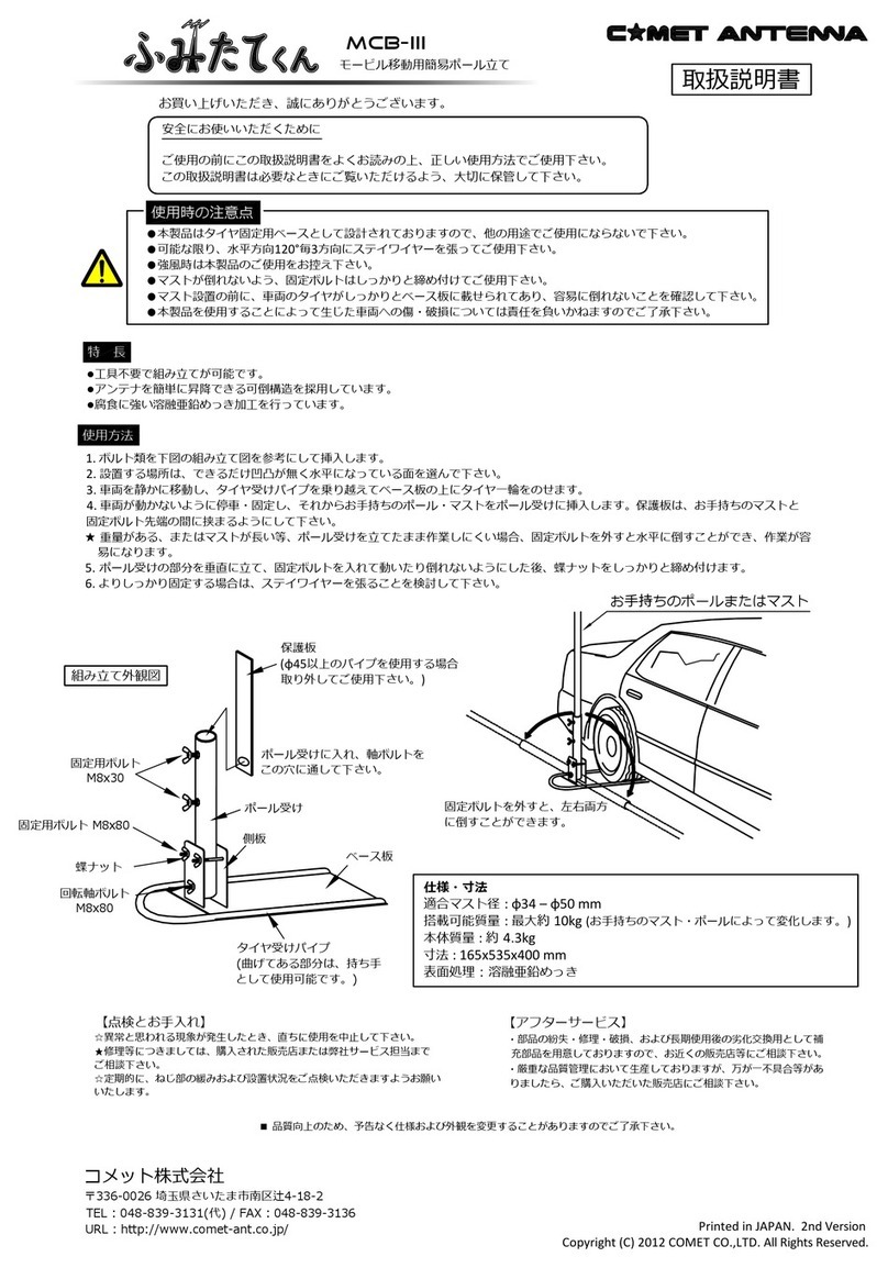
Comet MCB-III User manual

Comet
Comet CHA-250BX User manual

Comet
Comet Super Beam CSB790A User manual

Comet
Comet CAT-300 User manual

Comet
Comet CA-F72GF User manual

Comet
Comet CWD-230 User manual

Comet
Comet VA-250 User manual

Comet
Comet CFM-95SL User manual

Comet
Comet H-422 User manual
Popular Antenna manuals by other brands

Huawei
Huawei Straight Talk H258C user guide

Directive Systems & Engineering
Directive Systems & Engineering DSE2345LY quick start guide

EndRun
EndRun Window-Mount GPS Antenna installation guide

KVH Industries
KVH Industries TracVision L3 owner's manual

Amphenol Procom
Amphenol Procom GF 405/ Series quick start guide

RR Electronic
RR Electronic IBIZA 4G AIS Mounting instructions