Comet T4111 User manual

T4111 TRANSDUCER
Programmable temperature transducer
from Pt1000 sensor to current loop 4-20 mA
Instruction Manual
©Copyright: COMET SYSTEM, Ltd.
It is prohibited to copy and make any changes in this manual, without explicit agreement
of company COMET SYSTEM, Ltd. All rights reserved.
COMET SYSTEM, Ltd. makes constant development and improvement of their products.
Manufacturer reserves the right to make technical changes to the device without previous notice.
Misprints reserved.
Manufacturer is not responsible for damages caused by using the device in conflict with this
manual.
To damages caused by using the device in conflict with this manual cannot be provide free repairs
during the warranty period.
Read carefully instruction manual before the first device connection.
Contact address of this device’s producer:
COMET SYSTEM, s.r.o.
Bezrucova 2901
756 61 Roznov pod Radhostem
Czech Republic
www.cometsystem.com

2 IE-SNC-T4111-06
Instruction manual for use of T4111 transducer
Transducer is designed for temperature measurement at °C or °F by means of an external
temperature probe with Pt1000 sensor. Measured temperature is converted to linearized unified
signal 4-20 mA. Measured values are displayed on LCD display. It is possible to switch OFF
the LCD at all. Current loop has two-wire connection and requires power from evaluation device.
All transducer setting is performed by means of the PC connected via the optional SP003
communication cable (not included in delivery). Program Tsensor for transducer setting is available
to download free at www.cometsystem.com. Program enables to assign temperature measuring
range. It supports make the adjustment of the device too. This procedure is described at file
„Calibration manual.pdf“ which is installed commonly with the software.
Transducer version TxxxxLwith watertight male connector instead of a cable gland is
designed for easy connection/disconnection of the output cable. The protection of male Lumberg
connector RSFM4 is IP67.
Models marked TxxxxZare non-standard versions of the transducers. Description is not
included in this manual.
Please read instruction manual before the first device connection.
Device setting from the manufacturer
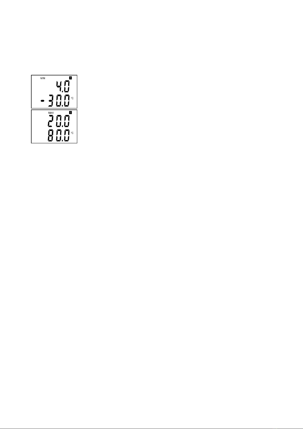
Transducer is set from the manufacturer to the following parameters:
value at output I1: 4 –20 mA corresponds -200 to +600 °C
display: switched ON
Modification of the setting is possible to do by means of the PC using procedure described
at the end of this document.
Installation of the transducer
Transducer is designed for wall mounting. There are two mounting holes at the sides of
the case. Interconnection terminals of T4111 are accessible after unscrewing four screws
and removing the lid. Lace the cable through a gland at the case wall. Connect the cable to terminals
with respecting the signal polarity (see figure). Terminals are self-clamping and can be opened by
a suitable screwdriver. For the opening, insert the screwdriver to upper terminal hole and lever by
him. Do not remember to tighten glands and case lid with inserted packing after cables connecting.
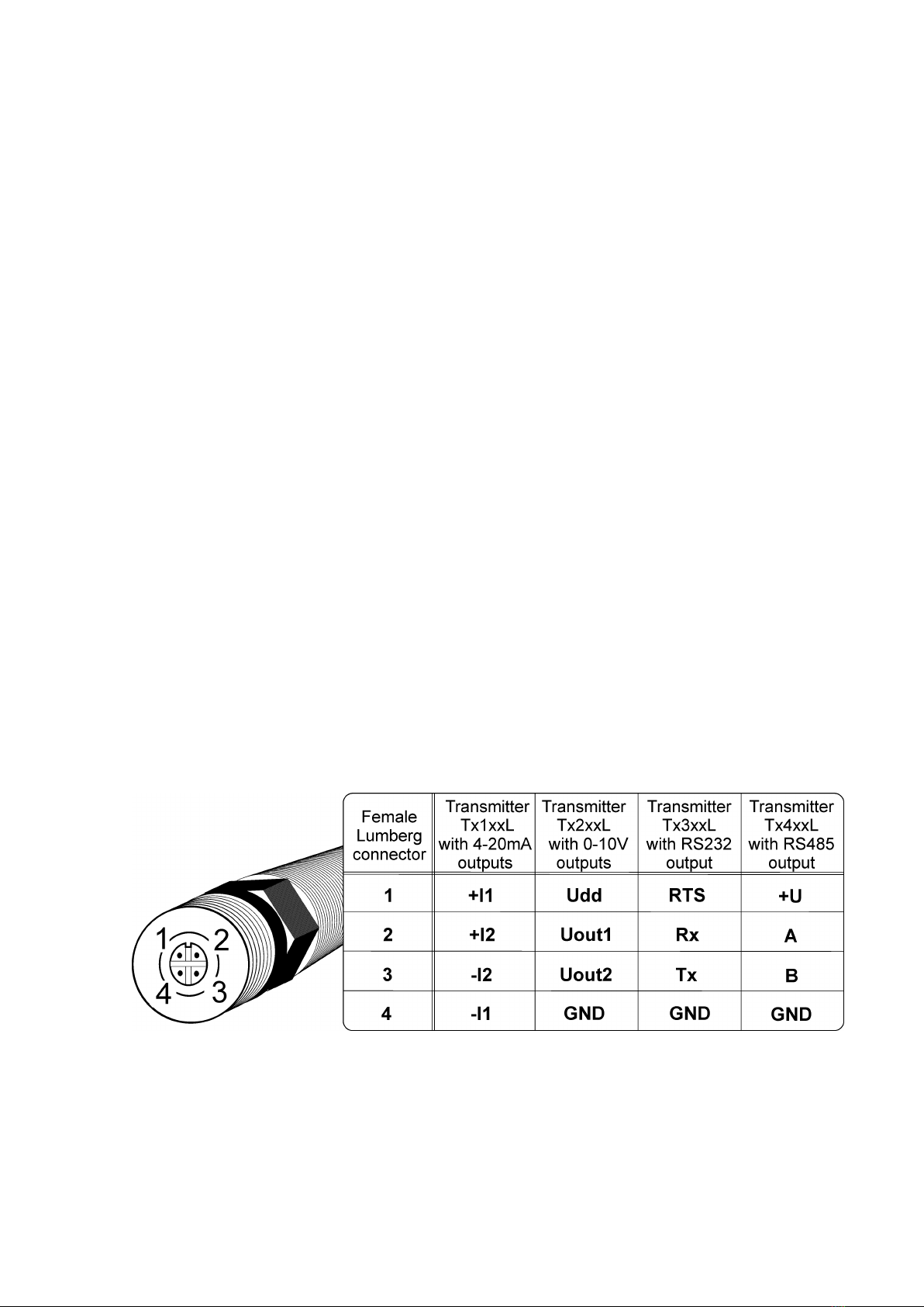
It is necessary for warranting of protection IP65. Connect complementary female connector
for T4111L transmitter in accordance with the table in Appendix A of this manual.
It is recommended to use shielded twisted copper cable, maximal length 1200m. The cable
must be located at indoor rooms. The cable should not be led in parallel along power cabling. Safety
distance is up to 0.5 m, otherwise undesirable induction of interference signals can appear. Outside
diameter of the cable for T4111 device must be from 3,5 to 8 mm (e.g. SYKFY), for device T4111L
with respect to the female connector. Do NOT connect shielding at connector side.
External temperature probe should be of „shielded two-wire“type. For leading of the cable
same recommendations are valid as for current loop cable, i.e. cable should be located as far
as possible from potential interference sources. Maximum probe cable length is 10 m. Connect
probe cable shielding to proper terminal and do not connect it to any other circuitry and do not
ground it. If connected probe is equipped with metal stem, we recommend using probes with metal
stem not connected to cable shielding. Or else it is necessary to arrange metal stem is not connected
to any other circuitry.
Electrical system (wiring) may do only worker with required qualification by rules
in operation.

IE-SNC-T4111-06 3
Dimensions –T4111
Connection:
Dimensions –T4111L
Connection: see Appendix A
Typical application wiring
Calculation of minimum power voltage Uss for
proper operation:
Uss min> Uo min + Imax * Rz,
where: Uo min= 9 V
Imax... approximately 20 mA
Rz... sensing resistor (shunt)

4 IE-SNC-T4111-06
LCD Info mode
Several settings of installed transducer is possible to verify without a use of the computer. It is
necessary to connect at least power of current loop I1.
Unscrew the transducer lid and shortly press button between display and interconnection
terminals by means of a tool (e.g. screwdriver).
Range and type of value for output 1 (current loop I1 = symbol „1“on
display). Type of value, assigned to output 1, is indicated by displayed unit
(here °C). Upper line displays current value corresponding to measured
value (lower line). Here 4 mA corresponds to -30 °C.
Press button again to get value for upper point (same output, same value)
similarly as at previous point. Here 20 mA corresponds to 80 °C.
Press button again to end info mode and display actual measured values.
Notice: during info mode no measurement and no output current generation
proceed. The transducer stays at info mode 15 s, then automatically goes back to measuring cycle.
Readings on LCD display
°C, °F
Reading next to this symbol is measured temperature or error state of value.
Technical parameters:
Analog output:
Current loop with range from 4 to 20 mA
Current output in case of error: <3.8 mA or >24 mA
Measuring parameters:
Temperature probe: Pt1000/3850 ppm connected by shielded cable of maximum
length 10m
Measuring temperature range: -200 to +600 °C (can be limited by applied
temperature probe model)
Resolution: 0.1 °C
Accuracy without probe: current output ± (0,15 + 0,1% FS) °C, ±0,2 °C for value on
LCD display
Recommended interval of calibration: 2 years
Measuring interval and LCD display refresh: 0.5 s
Communication with computer: via USB port by means of USB communication
cable SP003
Power: 9 to 30 V dc, maximum ripple 0.5 %
Protection: IP65

IE-SNC-T4111-06 5
Operating conditions:
Operating temperature range: -30 to +80 °C, over +70 °C switch LCD display OFF
external probe - depends on probe model.
Operating humidity range: 0 to 100 %RH
Outer characteristics in accordance with Czech National Standard 33-2000-3:
normal environment with the specifications: AE1, AN1, BE1
Working position: arbitrary
Electromagnetic compatibility: complies EN 61326-1
Not allowed manipulations: It is not allowed to operate the device under other than
specified conditions in technical parameters. Devices are not designed for locations
with chemically aggressive environment.
Storing conditions: temperature -30 to +80 °C
humidity 0 to 100 %RH without condensation
Dimensions: see dimensional drawings
Weight: approximately 145 g
Material of the case: ASA
Procedure of modification of transducer adjustment:
•Device adjustment is performed by means of the optional SP003 communication cable,
connected to USB port of the PC.
•It is necessary to have installed configuration program Tsensor on the PC. It is free to
download at www.cometsystem.com. During installation please take care about
installation of driver for USB communication cable.
•Connect SP003 communication cable to the PC. Installed USB driver detect connected
cable and create virtual COM port inside the PC.
•Unscrew four screws of the device lid a remove the lid. If device is already installed to
measuring system, disconnect leads from terminals.
•Connect SP003 communication cable to the device. Display must light up, or at least
must light up all symbols for one second (if LCD was switched OFF by program
before).
•Run installed Tsensor program and select corresponding communication COM port (as
described above).
•When new setting is saved and finished, disconnect the cable from the device, connect
leads into its terminals and place the lid back to the device.
Error States of the device
Device continuously checks its state during operation. In case error is found LCD displays
corresponding error code:
Error 0
First line displays „Err0“.
Check sum error of stored setting inside device’s memory. Output value is < 3.8 mA. This error
appears if incorrect writing procedure to device’s memory occurred or if damage of calibration data
appeared. At this state device does not measure and calculate values. It is the serious error, contact
distributor of the instrument to fix.

6 IE-SNC-T4111-06
Error 1
Measured value is over upper limit of allowed full scale range. There is a reading „Err1“ on LCD
display. Output value is about 24.5 mA. This state appears if measured temperature is higher than
approximately 600°C (i.e. high non-measurable resistance of temperature probe, probably opened
circuit).
Error 2
There is a reading „Err2“ on LCD display. Output value is about 3.8 mA. Measured value is below
lower limit of allowed full scale range. This state appears if measured temperature is lower than
approximately -210°C (i.e. low resistance of temperature probe, probably short circuit).
Error 3
There is a reading „Err3“ on LCD display upper line.
Error of internal A/D converter appeared (converter does not respond, probably damage of A/D
converter). No measurement of values is proceeded. Output value is about 3.8 mA. It is a serious
error, contact distributor of the instrument.
End of operation
Device itself (after its life) is necessary to liquidate ecologically!
Technical support and device service
Technical support and service is provided by distributor. For contact see warranty certificate.
Appendix A
Table of contents
Other Comet Transducer manuals
Popular Transducer manuals by other brands

KYOWA
KYOWA PGM-D Series instruction manual

Ashcroft
Ashcroft CXLdp Installation and maintenance sheet

Airmar
Airmar P79 Owner's guide and installation instructions

Simrad
Simrad ES120-7F - REV C datasheet

Airmar
Airmar TRIDUCER P23 Owner's guide & installation instructions

gefran
gefran ONP1-A Series installation manual