CURRENT MONITORING INSTALLATION GUIDE
Z20236
5-
0G
PAGE 1 ©2009 Veris Industries USA 800.354.8556 or 503.598.4564 / suppor[email protected] 05092Alta Labs, Enercept, Enspector, Hawkeye, Trustat, Veris, and the Veris ‘V’ logo are trademarks or registered trademarks of Veris Industries, L.L.C. in the USA and/or other countries.
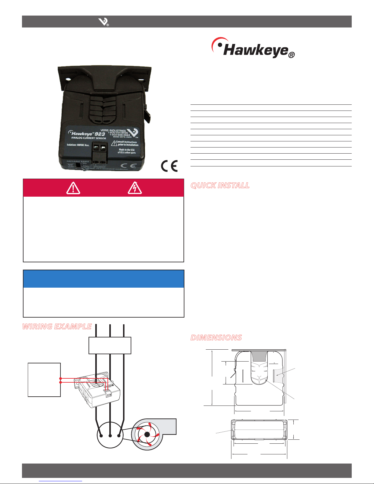
Split-Core Current Transducer,
0-10VDC Output
Installer’s Specifications
Amperage Range 0-20/100/150A (slide-switch selectable)
Sensor Power Induced from monitored current
Insulation Class 300VAC RMS
Frequency Range 50/60Hz
Temperature Range -15° to 60°C (5° to 140°F)
Humidity Range 10 - 90% RH, non-condensing
Accuracy ±2% full scale from 10% to 100% (selected range)
Response Time 2 sec.
Terminal Block Maximum Wire Size 14 AWG
Terminal Block Torque (nominal) 4 in-lbs (0.45 N-m)
Agency Approvals CE: EN61010-1:2001-2, CAT III, deg. 2, basic insulation
For applications requiring double or reinforced insulation, please contact the factory
)";"3%0'&-&$53*$4)0$,&91-04*0/03"3$'-"4)
t 'PMMPXTBGFFMFDUSJDBMXPSLQSBDUJDFT
4FF/'1"&JOUIF64"PSBQQMJDBCMFMPDBMDPEFT
t 5IJTFRVJQNFOUNVTUPOMZCFJOTUBMMFEBOETFSWJDFECZRVBMJmFEFMFDUSJDBMQFSTPOOFM
t 3FBEVOEFSTUBOEBOEGPMMPXUIFJOTUSVDUJPOTCFGPSFJOTUBMMJOHUIJTQSPEVDU
t 5VSOPõBMMQPXFSTVQQMZJOHFRVJQNFOUCFGPSFXPSLJOHPOPSJOTJEFUIFFRVJQNFOU
t 6TFBQSPQFSMZSBUFEWPMUBHFTFOTJOHEFWJDFUPDPOmSNQPXFSJTPõ
%0/05%&1&/%0/5)*4130%6$5'0370-5"(&*/%*$"5*0/
t 0OMZJOTUBMMUIJTQSPEVDUPOJOTVMBUFEDPOEVDUPST
'BJMVSFUPGPMMPXUIFTFJOTUSVDUJPOTXJMMSFTVMUJOEFBUIPSTFSJPVTJOKVSZ
%"/(&3
Wiring ExamplE
H923 923
DimEnsions
/05*$&
t 5IJTQSPEVDUJTOPUJOUFOEFEGPSMJGFPSTBGFUZBQQMJDBUJPOT
t %POPUJOTUBMMUIJTQSPEVDUJOIB[BSEPVTPSDMBTTJmFEMPDBUJPOT
t 5IFJOTUBMMFSJTSFTQPOTJCMFGPSDPOGPSNBODFUPBMMBQQMJDBCMFDPEFT
t .PVOUUIJTQSPEVDUJOTJEFBTVJUBCMFmSFBOEFMFDUSJDBMFODMPTVSF
Fan or Pump
CONTROLLER
0-10VDC
COMMON –
+
AI
CONTACTOR
Removable Mounting Bracket
Self-gripping
Iris
1.0”
(25 mm)
0.8”
(21 mm)
1.1”
(26 mm)
3.1”
(79 mm)
2.8”
(70 mm)
Ø = 0.3”
(8 mm)
1.4”
(36 mm)
2.5”
(64 mm)
3.0”
(76 mm)
Bracket can be mounted
on either side for added
installation flexibility.
Use DIN Rail
Mounting clip
(Veris part
number AH01) to
mount on stan-
dard DIN rail.
quick install
Disconnect and lock out power to the conductor to be monitored.1.
Plan the installation:2.
Locate a mounting surface for the removable mounting bracket that will allow
the monitored conductor to pass through the iris, or “window” when it is installed
and keep the product at least ½” (13mm) from any uninsulated conductors (CE).
Determine cable routing for the controller connection, allowing wiring to reach
the mounting location.
Install mounting bracket3.
Drill holes to mount the bracket to the chosen surface using the included screws.
Set the desired amperage range (20, 100, or 150 Amps).4.
Wire the output connections between the sensor and the controller (0-10VDC).5.
Snap thesensor over the wire to be monitored and clip the assembly to the6.
mounting bracket.
Scale the controller software to match the sensor output.7.
Close up and power up.8.


